Table of Contents
Advertisement
Quick Links
TT-3026L easyTrack Transceiver
Installation Manual
Thrane & Thrane
TT-3026L easyTrack Transceiver
Installation Manual
Copyright Thrane & Thrane A/S
ALL RIGHS RESERVED
2005, Thrane & Thrane A/S
Information in this document is subject to change without
notice and does not represent a commitment on the part of
Thrane & Thrane A/S.
Document number: 98-121788
Revision: A
th
Release Date: 16
of December 2005
1/60
Advertisement
Table of Contents

Subscribe to Our Youtube Channel
Related Manuals for Thrane&Thrane TT-3026L easyTrack


Summary of Contents for Thrane&Thrane TT-3026L easyTrack
- Page 1 TT-3026L easyTrack Transceiver Installation Manual Thrane & Thrane TT-3026L easyTrack Transceiver Installation Manual Copyright Thrane & Thrane A/S ALL RIGHS RESERVED 2005, Thrane & Thrane A/S Information in this document is subject to change without notice and does not represent a commitment on the part of Thrane &...
- Page 2 TT-3026L easyTrack Transceiver Installation Manual This page is intentionally left blank 2/60...
- Page 3 TT-3026L easyTrack Transceiver Installation Manual SAFETY SUMMARY The following general safety precautions must be observed during all phases of operation, service and repair of this equipment. Failure to comply with these precautions or with specific warnings elsewhere in this manual violates safety standards of design, manufacture and intended use of the equipment.
- Page 4 TT-3026L easyTrack Transceiver Installation Manual This page is intentionally left blank 4/60...
-
Page 5: Table Of Contents
Introduction ........14 Initial Inspection............14 Storage..............16 Repacking for shipment ...........16 Additional manuals ..........18 Abbreviations ............18 System Description ......20 TT-3026L easyTrack Transceiver ......21 TT-3616T Interconnection Box........23 TT-3606L Message Terminal ........24 EasyMail..............25 Accessories..............25 Registration ........27 Hardware Installation ......32 Installation of TT-3026L ..........33 4.1.1... - Page 6 TT-3026L easyTrack Transceiver Installation Manual Technical Specification ..........60 Software Installation ......62 About easyMail ............62 Before you install .............62 easyMail installation ..........63 5.3.1 CD startup............63 5.3.2 Starting the installation ........64 5.3.3 Start up window ..........64 5.3.4 Welcome screen ..........65 5.3.5 Disclaimer window ...........65...
- Page 7 TT-3026L easyTrack Transceiver Installation Manual List of Figures: Figure 1 TT-3026L easyTrack Mini-C Transceiver ....14 Figure 2 easyTrack system example........20 Figure 3 TT-3026L easyTrack Transceiver……………………..14 Figure 4 TT-3616B/T Interconnection Box......23 Figure 5 TT-3606L Message Terminal ........24 Figure 6 Page 1 of the Service Activation Registration Form .30 Figure 7 Minimum easyTrack system........32...
- Page 8 TT-3026L easyTrack Transceiver Installation Manual List of Tables: Table 1 Answers to selected questions in SARF.....31 Table 2 Radiated intensity .............39 Table 3 Cable pin assignment ..........40 Table 4 Transceiver Cable Terminal Block......48 Table 5 Power & I/O Cable Terminal Block ......51 Table 6 Jumper index ............52...
-
Page 9: Introduction
A wide variety of options and accessories may be linked together with the easyTrack transceiver. Those associated with the installation of the TT-3026L are described in this manual. Figure 1 TT-3026L easyTrack Mini-C Transceiver NITIAL NSPECTION WARNING To avoid hazardous electrical shock, do not perform electrical tests if there is any sign of shipping damage to any portion of the outer cover. -
Page 10: Storage
Tighten all loose hardware. TORAGE The TT-3026L easyTrack may be stored or shipped in temperatures within the limits -40° C to +80° C. It is recommended that the TT-3026L easyTrack is unpacked immediately on delivery. EPACKING FOR SHIPMENT... -
Page 11: Additional Manuals
TT-3026L easyTrack Transceiver Installation Manual Wrap the TT-3026L easyTrack in heavy paper or plastic. Attach a tag indicating the type of service required, return address, model number and full serial number. Use a strong shipping container, e.g., a double-walled carton made of 160 kg test material. - Page 12 TT-3026L easyTrack Transceiver Installation Manual LESO Inmarsat-C Land Earth Station Operator Low Noise Amplifier (radio receiver) Mobile Earth Station Inmarsat-C Network Coordination Station Opt. Short for option Point of Service Activation Performance Verification Test SARF Service Activation Registration Form SCADA...
-
Page 13: System Description
TT-3026L easyTrack Transceiver Installation Manual YSTEM ESCRIPTION The system shown in Figure 2 corresponds to a TT-3026L easyTrack setup, where distance and speed are derived from pulses from the tacho graph normally found in the vehicle. The individual products are briefly introduced in this section. -
Page 14: Tt-3026L Easytrack Transceiver
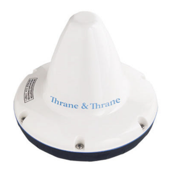
Figure 3 TT-3026L easyTrack Transceiver The TT-3026L easyTrack antenna has an elevation angle of -15° ensuring perfect reception even on steep slopes. The TT-3026L easyTrack has a built-in GPS module, capable of tracking up to 12 GPS satellites. 14/60... -
Page 15: Tt-3616T Interconnection Box
Installation Manual TT-3616T I NTERCONNECTION For connecting the TT-3026L easyTrack to peripheral equipment, it is recommended to use the optional TT-3616T Interconnection Breakout Box, designed to be mounted anywhere inside a vehicle and to be located up to 20 metres... -
Page 16: Tt-3606L Message Terminal
TT-3026L easyTrack Transceiver Installation Manual TT-3606L M ESSAGE ERMINAL The TT-3606L is a dedicated message terminal to be used in conjunction with the TT-3026L transceiver in order to send and receive messages to and from the vehicle. Figure 5 TT-3606L Message Terminal The TT-3606L Message Terminal is equipped with a touch screen. -
Page 17: Accessories
TT-3026L easyTrack Transceiver Installation Manual CCESSORIES Product Product description Picture number: Opt. 101 Standard 1” pole mount kit Opt. 103 Adjustable pole/railing mount kit Opt. 940 Connection cable, 5 meters, with 90° angular plug Opt. 941 Connection cable, 5 meters Opt. -
Page 18: Registration
TT-3026L easyTrack Transceiver Installation Manual EGISTRATION Before use of the easyTrack transceiver on the Inmarsat-C system it must be registered to the system, which involves a little paper work. This is done using the SARF (Service Activation Registration Form) supplied with the easyTrack MES. -
Page 19: Figure 6 Page 1 Of The Service Activation Registration Form
TT-3026L easyTrack Transceiver Installation Manual Figure 6 Page 1 of the Service Activation Registration Form 19/60... -
Page 20: Table 1 Answers To Selected Questions In Sarf
TT-3026L easyTrack Transceiver Installation Manual Question in SARF Answer Environment usage When installed in vehicles: Land Mobile. The System? Inmarsat-C Mobile Earth Station (MES) Thrane & Thrane A/S manufacturer Mobile Earth Station (MES) model TT-3026L Table 1 Answers to selected questions in SARF When the easyTrack MES is registered at the ISP it is ready to be used on the Inmarsat-C network. -
Page 21: Hardware Installation
TT-3026L easyTrack Transceiver Installation Manual ARDWARE NSTALLATION The TT-3026L easyTrack is equipped with an 18-pin female connector and is meant for flat surface mounting, or pole mounting using an optional adaptor. See section 4.1.1. Figure 7 shows the minimal easyTrack system configuration, where the transceiver is pre-configured for tracking. -
Page 22: Pole Mount 1
TT-3026L easyTrack Transceiver Installation Manual Place the friction gasket on the surface. Connect the cable and mount the screws. 4.1.1.2 1” OLE MOUNT 40-3026 Opt. 101 is a standard 1” pole mount, Illustrated in Figure 8. Pull the cable in the pole and adapter. -
Page 23: Adjustable Pole/Railing Mount
4.1.2 NTENNA OUNTING ONDITIONS When installing the TT-3026L easyTrack, find a location that is as free from obstructions as possible. Also maintain a certain distance to other antennas. The antenna is designed to provide satellite coverage even when the vehicle is tilted up to 15°. To maintain this coverage the antenna should be free from obstructions in the area down to 15°... -
Page 24: Figure 10 Viewing Angle To The Horizon
TT-3026L easyTrack Transceiver Installation Manual Zenith Horizon Horizon Obstructions should be below these lines Figure 10 Viewing Angle to the Horizon If an obstruction such as a pole is unavoidable, the Transceiver must be positioned in such a location that the obstruction covers no more than a 2°... -
Page 25: Safety Distance For Antenna Units
TT-3026L easyTrack Transceiver Installation Manual 4.1.3 AFETY ISTANCE FOR NTENNA NITS When transmitting, the electromagnetic field radiated from the antenna can be harmful. To avoid danger, keep a distance of 1 ft. (30 cm.) from the transceiver. To be sure that this distance is respected, the TT-3026L easyTrack is provided with a label declaring a minimum safety distance of 1 ft. -
Page 26: Grounding
GND (white or orange wire), the Transceiver will be switched on. This makes it possible for external equipment to perform remote power control of the TT-3026L easyTrack Transceiver. An external relay or solid-state switch can control the power. -
Page 27: Power Connection
4.2.4 OWER EQUIREMENTS The TT-3026L easyTrack transceiver is designed to operate on floating DC in the nominal range 12V to 24V, which makes an AC/DC converter needed, in case the system is to work in an AC environment. In case an AC/DC converter is used, please make sure to leave the output floating, i.e. - Page 28 TT-3026L easyTrack Transceiver Installation Manual Voltage allowed between GND and the output pin is 0V to 5V. Maximum allowed current into the I/O pin is 25mA. Note: There is no current limiter integrated in the output, thus the user must ensure, that the load connected is within limits.
-
Page 29: Installation Of Tt-3616T Interconnection Box
Installation Manual TT-3616T I NSTALLATION OF NTERCONNECTION For connecting the TT-3026L easyTrack to peripheral equipment, it is recommended to use the TT-3616T Interconnection box, which includes proper connectors for DTE (Data Terminal Equipment), I/O ports (remote transducers, alarm button, tacho graph), on/off wire and power supply. -
Page 30: Mounting Of Transceiver Cable
TT-3026L easyTrack Transceiver Installation Manual Transceiver Cable Transceiver Cable Strain Relief Points Access Port Terminal Block (J1) Transceiver Cable TACHO PROG Power & I/O Cable Tachograph Terminal Block (J2) Power & I/O Cable Strain Relief Points DB9 Connector for Data Terminal... - Page 31 TT-3026L easyTrack Transceiver Installation Manual 3) Wind the tinned wire around the sheath as shown: 4) Fasten the cable as shown: 5) The J1 terminal block is labelled by wire colour. Connect the transceiver cable as directed by these labels. The terminal number, colours and functions are explained in Table 4.
-
Page 32: Grounding Of Interconnection Box
TT-3026L easyTrack Transceiver Installation Manual Number on Terminal Wire colour in Function Block J1 transceiver cable Black/Yellow I/O 3 Black/Grey I/O 4 Brown I/O 5 Black/Green I/O 6 Yellow Remote On/Off Orange Blue CTS ** Violet RTS ** Green RD **... -
Page 33: Power & I/O Connection
TT-3026L easyTrack Transceiver Installation Manual Figure 14 Alternative grounding of Interconnection Box 4.3.3 ERMINAL QUIPMENT CONNECTION The DB9 Connector is connected to Data Terminal Equipment using a standard DB9 to DB9 Modem cable. 4.3.4 & I/O C OWER ONNECTION The J2 terminal block is labelled by pin function, as listed in Table 12. -
Page 34: Table 6 Jumper Index
TT-3026L easyTrack Transceiver Installation Manual Number on Function Terminal Block J2 AUX3 AUX2 Table 5 Power & I/O Cable Terminal Block The function of all jumpers shown in Figure 13 are listed in Table 7. The circles shown in Figure 13 are the default placement of jumpers. -
Page 35: Connecting A Tacho Graph
TT-3026L easyTrack Transceiver Installation Manual ONNECTING A ACHO GRAPH The TT-3616T is designed to interface to tacho graph devices with a pulse per meter output compatible with the specification given in Table 7. A common standard is a calibration of 4 impulses per meter, but other ratios can be used as well (software configurable, ref. -
Page 36: Figure 15 Grounding Scheme A
TT-3026L easyTrack Transceiver Installation Manual TT-3616T Terminal Block (J2) Tachograph Signal Signal Ground fuse Battery Figure 15 Grounding scheme A 36/60... -
Page 37: Figure 16 Grounding Scheme B
TT-3026L easyTrack Transceiver Installation Manual TT-3616T Terminal Block (J2) Tachograph Signal This signal Ground wire must be connected close to the Tachograph! fuse Battery Figure 16 Grounding scheme B 37/60... -
Page 38: Troubleshooting
TT-3026L easyTrack Transceiver Installation Manual ROUBLESHOOTING Example: When the 4 Impulses/meter (4 Imp/m) output from tacho graph model MTCO 1324 (VDO) is correctly installed to the TT-3616T interconnection box, the signal measured on terminal block J2 between GND and AUX3 with an oscilloscope will look like Ch1 on Figure 16 (0-8.5V signal) -
Page 39: Figure 18 Tacho Graph Signal With Missing Gnd Reference
TT-3026L easyTrack Transceiver Installation Manual look like Ch1 in Figure 17. The corresponding signal with correct GND connection is shown in Figure 18. Figure 18 Tacho graph signal with missing GND reference. Figure 19 Tacho graph signal with correct GND reference. -
Page 40: Dte Connection Via Db9 Female Connector
TT-3026L easyTrack Transceiver Installation Manual CONNECTION VIA FEMALE CONNECTOR An option for connection of a DTE is using the opt-944 Female 9-pole sub-D connector. Figure 20 Sub-D with screw terminals Wire colour in Terminal no in Function transceiver cable sub-D connector... -
Page 41: Technical Specification
TT-3026L easyTrack Transceiver Installation Manual ECHNICAL PECIFICATION Model TT-3026L General Specifications Meets all INMARSAT specifications for the Inmarsat mini-C Network for Land mobile and Maritime terminals. R&TTE Transmit Frequency 1626.5 to 1660.5 MHz. note 1 Receive Frequency 1525.0 to 1559.0 MHz. -
Page 42: Table 9 Tt-3026L Technical Spectifications
TT-3026L easyTrack Transceiver Installation Manual Operating system The TT-3026L easyTrack makes use of eCos™ operating system. Inmarsat-C Message transmission and reception with IA-5, ITA-2 and Protocol support binary transfer to/from the following destinations: Telex PSTN (telephone modems and fax modems) PSDN (X.25 network) -
Page 43: Software Installation
TT-3026L easyTrack Transceiver Installation Manual OFTWARE NSTALLATION BOUT EASY EasyMail is a PC program, which can be used to control Thrane & Thrane Inmarsat-C transceivers. With easyMail you can easily send and receive e-mail, SMS, fax and telex messages, set up position reporting and many other things. -
Page 44: Starting The Installation
TT-3026L easyTrack Transceiver Installation Manual If the program does not start automatically, run start.htm from your CD drive. 5.3.2 TARTING THE INSTALLATION Click ‘Install easyMail’. 44/60... -
Page 45: Start Up Window
TT-3026L easyTrack Transceiver Installation Manual 5.3.3 TART UP WINDOW Click ‘Next’. 5.3.4 ELCOME SCREEN Click ‘Next’. 45/60... -
Page 46: Disclaimer Window
TT-3026L easyTrack Transceiver Installation Manual 5.3.5 ISCLAIMER WINDOW Read the disclaimer Click the button ‘ I accept the terms in the license agreement’ Click ‘Next’ 5.3.6 USTOMER INFORMATION 46/60... -
Page 47: Destination Folder
TT-3026L easyTrack Transceiver Installation Manual Type user name and organisation Click ‘Next’. 5.3.7 ESTINATION FOLDER Choose destination folder (Default and recommended folder is C:\Program Files\easyMail) Click ‘Next’. 47/60... -
Page 48: Ready To Install
TT-3026L easyTrack Transceiver Installation Manual 5.3.8 EADY TO INSTALL Click ‘Install’ to begin installing easyMail. 5.3.9 NSTALL COMPLETED Click ‘Finish’ to complete the installation procedure. 48/60... -
Page 49: Starting Easymail
TT-3026L easyTrack Transceiver Installation Manual 5.3.10 S TARTING EASY easyMail can be started in one of two ways: 1. Click the easyMail icon on the desktop. 2. Start easyMail from StartProgramsThrane & ThraneeasyMail 1.10 The easyMail main window below will be shown. -
Page 50: Figure 21 Easymail With No Connection To Easytrack
TT-3026L easyTrack Transceiver Installation Manual Figure 21 easyMail with no connection to easyTrack After a few seconds, the fields should change to this: Figure 22 easyMail connected to easyTrack, good satellite signal and GPS fix. If the fields look like Figure 21, please go on to 5.5 easyMail basic setup. -
Page 51: Easymail Basic Setup
TT-3026L easyTrack Transceiver Installation Manual This bar has 5 steps from all green to all red, depending on the quality of the satellite signal. Green: good signal quality. Red: no signal. PC connect Green: easyMail has connected to easyTrack. Red: No... -
Page 52: Figure 23 Example Of Mobile Number
TT-3026L easyTrack Transceiver Installation Manual Figure 23 Example of Mobile number Log in to an Ocean Region Figure 24 The login menu Go to the menu OptionsLogin and choose between the 4 Ocean Regions depending on your current position. After a short while the Mobile status field has changed: Figure 25 Example when logged in to East Atlantic You have now logged in to the Inmarsat satellite network. -
Page 53: Getting New Versions Of Easymail
TT-3026L easyTrack Transceiver Installation Manual Click OptionsSet Default ISP… Figure 26 Choose your Service Provider Choose your Inmarsat Service Provider on the list. Click ‘OptionsSet Default LES…’ Figure 27 Land Earth Stations (LESs) of your Inmarsat Service Provider Choose the Land Earth Stations of your Inmarsat Service Provider for each Ocean Region. -
Page 54: Test Of The System
TT-3026L easyTrack Transceiver Installation Manual EST OF THE SYSTEM INK TEST A link test (or PVT test) tests the satellite link from the transceiver to the Land Earth Station. A link test is initiated by clicking ‘OptionsLink test’. Make sure the transceiver is logged in before starting the link test. -
Page 55: Maintenance Guidelines
TT-3026L easyTrack Transceiver Installation Manual AINTENANCE GUIDELINES When properly installed the TT-3026L needs no maintenance. After approximately 10 years an internal battery has to be replaced, and the transceiver must be sent for service. Low battery level will result in loss of configuration data in case the unit is powered down. -
Page 56: Mounting Stencil
TT-3026L easyTrack Transceiver Installation Manual PPENDIX OUNTING STENCIL Figure 29 Mounting stencil For connector: predrilled hole 32mm (1.26”) diameter A: 3 x predrilled holes 5mm (0.2”) diameter for M4 screws. 56/60... -
Page 57: Interconnection Box Tt-3616B
Installation Manual PPENDIX TT-3616B NTERCONNECTION BOX For connecting the TT-3026L easyTrack to peripheral equipment without tacho graph input, the TT-3616B interconnection box can be used. It includes proper connectors for DTE (Data Terminal Equipment), I/O ports (remote transducers, alarm button), on/off wire and power supply. -
Page 58: Figure 31 Interconnection Box Interior Arrangement
TT-3026L easyTrack Transceiver Installation Manual Transceiver Cable Transceiver Cable Strain Relief Points Access Port Transceiver Cable Terminal Block (J1) Power & I/O Cable Terminal Block (J2) Power & I/O Cable Strain Relief Points DB9 Connector for Data Terminal Equipment Power Indicator Power &... -
Page 59: Table 10 Transceiver Cable Terminal Block
TT-3026L easyTrack Transceiver Installation Manual Number on Wire colour in Function Terminal Block J1 transceiver cable Grey I/O 2 Black/Yellow I/O 3 Black/Grey I/O 4 Brown I/O 5 Black/Green I/O 6 Yellow Remote On/Off Orange Blue CTS * Violet RTS *... -
Page 60: Table 11 Power & I/O Cable Terminal Block
TT-3026L easyTrack Transceiver Installation Manual Number on Terminal Block J2 Function Table 11 Power & I/O Cable Terminal Block Jumper W2 enables LED 1, which indicates DC in. 60/60...
Need help?
Do you have a question about the TT-3026L easyTrack and is the answer not in the manual?
Questions and answers