Table of Contents
Advertisement
Advertisement
Table of Contents

Subscribe to Our Youtube Channel
Related Manuals for Thrane&Thrane TT-3020C


Summary of Contents for Thrane&Thrane TT-3020C
- Page 1 Maritime Capsat Transceiver TT-3020C Installation Manual...
- Page 3 Thrane & Thrane Thrane & Thrane Thrane & Thrane Thrane & Thrane Maritime Capsat Transceiver TT-3020C Installation Manual Copyright Thrane & Thrane A/S ALL RIGHTS RESERVED...
- Page 4 Information in this document is subject to change without notice and does not represent a commitment on the part of Thrane & Thrane A/S. © 2000 Thrane & Thrane A/S. All right reserved. Printed in Den- mark. Document Number TT98-107880-C. Release Date: 25.
- Page 5 Radiated intensity at 0.56m is 10 W/m Radiated intensity at 0.36m is 25 W/m Radiated intensity at 0.18m is 100 W/m COMPASS SAF COMPASS SAF COMPASS SAF COMPASS SAFE DISTANCE E DISTANCE E DISTANCE E DISTANCE Minimum safety distance of 50 cm from the TT-3020C transceiver...
- Page 6 This page is intentionally left blank...
-
Page 7: Table Of Contents
Table of Contents Table of Contents Introduction ..................1-1 Initial Inspection ............... 1-1 Storage ..................1-2 Repackaging for shipment............1-2 Installation - TT-3020C............... 2-1 Technical specifications............2-1 Compass Safe Distance............. 2-3 Power requirements ..............2-4 2.3.1 Fuse ................2-4 Functional description .............. 2-4 2.4.1... - Page 8 Installation ..............3-52 3.9.3 Connectors ..............3-52 3.9.4 Cable.................3-53 3.9.5 Specifications.............3-55 3.10 Distress Button Test ..............3-56 3.10.1 TT-3020C Transceiver..........3-56 3.10.2 TT-3042C Remote Alarm/Distress Box .......3-57 3.10.3 TT-3042D Remote Alarm Distress Box ......3-57 3.11 General interconnect information ...........3-58 System Generation ................4-1 Terminal Mode................4-1 4.1.1 TT-3606E Message Terminal ........4-1...
- Page 9 Figure 1 TT-3020C Maritime Capsat Transceiver ........1-1 Figure 2TT-3020C Capsat Transceiver rear panel ........2-7 Figure 3 TT-3020C Capsat Transceiver mounting plate......2-19 Figure 4 Front panel of the TT-3020C Capsat Transceiver with mounting bracket ..................2-19 Figure 5 TT-3005M Maritime Antenna ............3-5 Figure 6 TT-3005M 1’’...
- Page 10 Table of Figures Table of Figures Table of Figures Table of Figures This page is intentionally left blank Page Page iv iv iv iv Page Page 25-Jul-00 25-Jul-00 25-Jul-00 25-Jul-00...
- Page 11 Table 17 TT-3020C Capsat Transceiver Antenna Cable types (TNC - TNC) for TT-3005A antenna............... 3-13 Table 18 TT-3001B opt. 001 Technical Specifications......... 3-16 Table 19 TT-3020C Capsat Transceiver Antenna Cable types (N - TNC) for TT-3001B opt. 001................. 3-17 Table 20 Radiated intensity ............... 3-22 Table 21 TT-3606E Power Connector............
- Page 12 Table of Tables Table of Tables Table of Tables Table of Tables Table 29 TT-3042D DIP switch settings............3-51 Table 30 TT-3042D Power Connector ............3-52 Table 31 TT-3042D I/O Connector..............3-53 Table 32 TT-3042D Technical Specifications ..........3-55 Table 33 Antenna voltage configuration............4-4 Page Page vi vi vi vi Page...
-
Page 13: Introduction
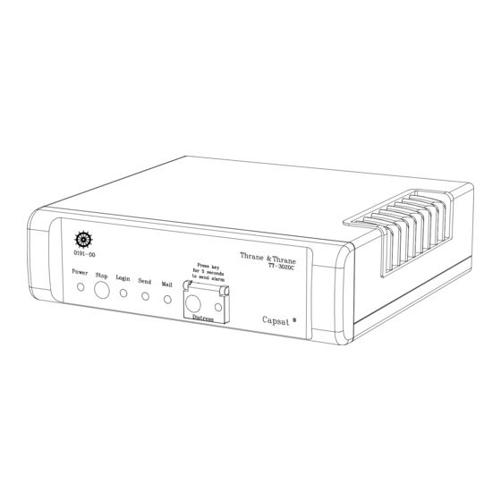
A wide variety of options and accessories may be linked together with the Capsat Transceiver, the specific installation and config- uring of these are to be found in their respective Reference Manuals. Figure 1 TT-3020C Maritime Capsat Transceiver Initial Inspection WARNING WARNING... -
Page 14: Storage
Storage The TT-3020C may be stored or shipped in temperatures within the limits -40° C to +80° C. It is advisable to protect the TT-3020C from extreme temperature variation which can cause excessive condensation. It is recommended that the TT-3020C is unpacked immediately on delivery. - Page 15 If the original shipping carton is not available, the following gen- eral instructions should be used for repackaging with commer- cially available material. 1. Wrap the TT-3020C in heavy paper or plastic. Attach a tag in- dicating the type of service required, return address, model number and full serial number.
- Page 16 Introduction Introduction Repackaging for shipment Repackaging for shipment Introduction Introduction Repackaging for shipment Repackaging for shipment This page is intentionally left blank Page Page 1-4 Page Page 25-Jul-00 25-Jul-00 25-Jul-00 25-Jul-00...
-
Page 17: Installation - Tt-3020C
Installation - TT-3020C Installation - TT-3020C This chapter provides specific information enabling you to install the TT-3020C Capsat Transceiver into your own system, with a minimal effort. The default, or factory configuration is described, together with procedures for altering this configuration. -
Page 18: Table 1 Tt-3020C Technical Specifications
-40°C to 80°C storage. Electronic Unit Mounting Mounting bracket. Dimensions H x W x D 50mm x 180mm x 165mm. ( car radio standard ISO7736 ) Weight 1.3 kg Table 1 TT-3020C technical specifications. Page Page 2-2 Page Page 25-Jul-00 25-Jul-00 25-Jul-00... -
Page 19: Compass Safe Distance
SOLAS distress calling facilities. Table 2 Inmarsat-C Protocol support. Compass Safe Distance The compass safe distance of the TT-3020C transceiver has been measured in accordance with the standards specified in ISO/R 694, Method B. The safe distance found is 50 cm. -
Page 20: Power Requirements
Table 3 TT-3020C power requirements 2.3.1 Fuse The TT-3020C has a single fuse, which can be found on the rear panel. In case it needs replacement a 12 A T type must be used. Functional description This section describes the functions of the TT-3020C Maritime Capsat transceiver. -
Page 21: Front Indicators And Buttons
Installation - TT-3020C Installation - TT-3020C on the rear panel of the TT-3020C Transceiver, and the remote on/off wire (white) in the DC input cable. Please see Table 5 for more information about remote on/off. The priority of the differ- ent functions are defined in Table 4. - Page 22 If the Transceiver is unable to get synchronisation the indicator will be off. Please notice that the TT-3020C during power-up will at- tempt to auto-login to a preferred ocean region if currently logged out of the network.
-
Page 23: Connectors
Power connector The battery connector is a standard DB-15 male, located on the rear panel of the TT-3020C at X1. Regardless whether the unit is designed to work on floating DC or modified to match your DC requirements the pin assignment of the DC/Battery power connector and DC cable matches the de- scription given in Table 5. -
Page 24: Table 5 Tt-3020C Capsat Transceiver Dc Power Connector Pin Assignment
Table 5 TT-3020C Capsat Transceiver DC Power Connector pin assignment Pin 6 is a unique feature for the TT-3020C Capsat Transceiver. When this pin is left floating the Transceiver is turned off, but if pin 6 is shorted to the negative terminal of the battery or DC- supply, the Transceiver will be switched on. -
Page 25: Dte Communication Port
2.5.2 DTE Communication port The TT-3020C Capsat Transceiver communicates with a controller device via the standard EIA/TIA-232E ports on a female 9 pole Sub-D connector, located on the rear panel at X3. -
Page 26: Table 7 Tt-3020C X3 Pin Assignment
Installation - TT-3020C Installation - TT-3020C Connectors Connectors 2.5.2.2 DTE Connector interface The TT-3020C which is a DCE uses the signals listed in Table 7 (marked with a in the Used column).Please notice that DTE pin naming is used. Name Name... -
Page 27: I/O Connector
Hardware flow control is accomplished by using the DTR and CTS signals. Software flow control is accomplished by connecting the DTR and CTS, allowing both TT-3020C and the peripheral to control data flow by means XON XOFF. ENQ/ACK cannot be used. 2.5.3... -
Page 28: Table 8 Tt-3020C X4 Pin Assignment
Digital input with pull-up (RS-410N). I5 (I) Digital input with pull-up (RS-410N). Table 8 TT-3020C X4 pin assignment The I/O connector, a standard DB-15 female connector, is located on the rear panel of the transceiver and is marked X4. 2.5.3.1... - Page 29 Connectors Connectors Installation - TT-3020C Installation - TT-3020C Connectors Connectors Installation - TT-3020C Installation - TT-3020C Heading and speed information Transducer measurements Wind speed and angle Water temperature The following is a list of the NMEA codes that the Transceiver will recognise, if you do not have a built-in GPS or the built-in GPS is in acquisition mode.
- Page 30 Installation - TT-3020C Installation - TT-3020C Connectors Connectors Installation - TT-3020C Installation - TT-3020C Connectors Connectors 2.5.3.3 NMEA 0183 Transmission When your Transceiver has a built-in GPS, it sends out NMEA 0183 navigational data to the device connected to the Trans- ceiver, via the I/O NMEA connector X4.
-
Page 31: Printer Port
Connectors Connectors Installation - TT-3020C Installation - TT-3020C Connectors Connectors Installation - TT-3020C Installation - TT-3020C stored position is more than 24 hours old. The time field is empty. The course and speed are 8 second mean values. An example is: $GPVTG,139.,T,139.,M,02.0,N,00.0,K... -
Page 32: Table 9 Printer Port (X5) Pin Assignment
Installation - TT-3020C Installation - TT-3020C Connectors Connectors Installation - TT-3020C Installation - TT-3020C Connectors Connectors Name Signal Description STRB Strobe DAT0 Data Bit 0 DAT1 Data Bit 1 DAT2 Data Bit 2 DAT3 Data Bit 3 DAT4 Data Bit 4... -
Page 33: Grounding
Built-in GPS (optional) Built-in GPS (optional) Installation - TT-3020C Installation - TT-3020C Built-in GPS (optional) Built-in GPS (optional) Installation - TT-3020C Installation - TT-3020C 2.5.5 Grounding RF-grounding of an Integrated Capsat System requires special attention. Each unit shall have its own individual low-inductance earth connection. -
Page 34: Gps Specifications
15m RMS (100m with Selective Availability on) Typical velocity accuracy 0.2m/s RMS Table 10 GPS Specifications Mounting bracket The TT-3020C Capsat Transceiver is supplied with an universal mounting plate (41-107093-A) which allows mounting to e.g. a ta- ble. Page Page 2-18 Page... -
Page 35: Figure 3 Tt-3020C Capsat Transceiver Mounting Plate
Mounting bracket Installation - TT-3020C Installation - TT-3020C Figure 3 TT-3020C Capsat Transceiver mounting plate. All dimensions are in mm Figure 4 Front panel of the TT-3020C Capsat Transceiver with mounting bracket All dimensions are in mm 25-Jul-00 25-Jul-00 Page... - Page 36 Installation - TT-3020C Installation - TT-3020C Mounting bracket Mounting bracket Installation - TT-3020C Installation - TT-3020C Mounting bracket Mounting bracket It is recommended that the Transceiver is mounted in an open air location. Page Page 2-20 Page Page 2-20 2-20...
-
Page 37: System Installation
System Installation System Installation This chapter provides specific information enabling you to install the TT-3020C Maritime Capsat system with a minimal effort. The default, or factory configuration is described, together with pro- cedures for altering this configuration. The TT-3000C Integrated Capsat system consists of the following... -
Page 38: Fuses
System Installation System Installation Power requirements Power requirements Power requirements Receive Transmit mode mode TT-3020C Capsat Transceiver incl. TT-3005M 3.8W antenna. Max. Floating DC (10-32V). TT-3020C Capsat Transceiver Incl. TT-3005M 4.4W Antenna & GPS. Floating DC (10-32V). Max. TT-3606E Message Terminal, incl. Keyboard. -
Page 39: Compass Safe Distance
Compass Safe Distance System Installation System Installation As a guide-line, please note the equipment fuse location given in Table 12. Equipment Location Fuse size TT-3020C Capsat Externally accessed, 12A T. Transceiver incl. located on the rear Antenna. panel. TT-3606E Message... -
Page 40: Table 13 Compass Safe Distance
Compass Safe Distance Compass Safe Distance System Installation System Installation Compass Safe Distance Compass Safe Distance Model Compass Safe Distance TT-3020C, Transceiver 0.5 m TT-3606E Message Terminal 0.5 m TT-3601E Keyboard 0.3 m TT-3042C, Remote Alarm Distress 0.5 m TT-3601A, Keyboard 0.5 m... -
Page 41: Antennas
Antennas Antennas System Installation System Installation Antennas Antennas System Installation System Installation Antennas This section describes the different antennas types, which can be delivered with the TT-3000C Maritime Capsat system. The mounting consideration regarding the antennas and the choice of antenna cable are also described. - Page 42 System Installation System Installation Antennas Antennas System Installation System Installation Antennas Antennas The antenna is very compact and is designed to operate in a cor- rosive environment and in extreme weather conditions without any service. It has a modular construction that allows easy ex- change of antenna elements.
-
Page 43: Table 14 Tt-3005M Technical Specifications
Antennas Antennas System Installation System Installation Antennas Antennas System Installation System Installation TT-3005M Inmarsat-C/GPS omnidirectional Maritime Antenna antenna, RHC polarised. G/T: -23 dB/K at 5° elevation EIRP: 14 dBW ± 2dB at 5° elevation. Temperature: -35°C to 55°C operating, -40°C to 80°C storage. Dimensions (H x D): 178 mm x 122 mm. -
Page 44: Table 15 Tt-3020C Capsat Transceiver Antenna Cable Types
(11N-50-12-35C) and one adapter N female to TNC male (33TNC-N-50-51) Table 15 TT-3020C Capsat Transceiver Antenna Cable types (TNC - TNC) for TT-3005M. All antenna cables types are double shielded. The antenna cable may run together with radar or navigator ca- bles. -
Page 45: Figure 6 Tt-3005M 1'' Tube Mounting
Antennas Antennas System Installation System Installation Antennas Antennas System Installation System Installation with the enclosed self-bonding tape, disabling water from pene- trating the connection. 3.3.1.3 Mounting The TT-3005M maritime antenna is constructed for 1” tube mounting. Figure 6 TT-3005M 1’’ Tube Mounting It is important to notice that the pole mount device has to be dis- connected from the antenna body when the antenna cable should be mounted. -
Page 46: Tt-3005A Maritime Antenna
System Installation System Installation Antennas Antennas System Installation System Installation Antennas Antennas 3.3.1.4 Transceiver Configuration This new antenna is designed to use a very low amount of power. To ensure that the transceiver detects the antenna as connected the voltage output of the transceiver has to be reduced. Issuing the following command in the transceiver shell does this: “Se —f 0”... - Page 47 Antennas Antennas System Installation System Installation Antennas Antennas System Installation System Installation The antenna is very compact and is designed to operate in a cor- rosive environment and in extreme weather conditions without any service. It has a modular construction that allows easy ex- change of antenna elements.
-
Page 48: Table 16 Tt-3005A Technical Specifications
System Installation System Installation Antennas Antennas System Installation System Installation Antennas Antennas TT-3005A Inmarsat-C/GPS omnidirectional Maritime Antenna antenna, RHC polarised. G/T: -23 dB/K at 5° elevation EIRP: 14 dBW ± 2dB at 5° elevation. Temperature: -35°C to 55°C operating, -40°C to 80°C storage. Dimensions (H x G): 120 mm x 146 mm conical excl. -
Page 49: Table 17 Tt-3020C Capsat Transceiver Antenna Cable Types
(11N-50-12-35C) and two adapters N female to TNC male (33TNC-N-50-51) Table 17 TT-3020C Capsat Transceiver Antenna Cable types (TNC - TNC) for TT-3005A antenna. All antenna cables are double shielded. The antenna cable may run together with radar or navigator ca- bles. -
Page 50: Figure 8 Tt-3005A 1.5'' Tube Mounting
System Installation System Installation Antennas Antennas System Installation System Installation Antennas Antennas 3.3.2.3 Mounting The TT-3005A maritime antenna is constructed for 1.5” tube mounting. Figure 8 TT-3005A 1.5’’ tube mounting 3.3.2.4 Low antenna power in Rx mode The TT-3005A Antenna Rx power can be reduced from 1.1W with (14V) to 0.7W with (9V). -
Page 51: Tt-3001B Maritime Antenna
Antennas Antennas System Installation System Installation Antennas Antennas System Installation System Installation 3.3.3 TT-3001B Maritime Antenna Figure 9 TT-3001B opt. 001 Maritime Antenna This is an omni-directional antenna with built-in LNA/HPA elec- tronics designed to operate on vessels. The antenna housing is sealed and contains no user serviceable parts. -
Page 52: Table 18 Tt-3001B Opt. 001 Technical Specifications
System Installation System Installation Antennas Antennas System Installation System Installation Antennas Antennas TT-3001B Opt. 001 Inmarsat-C/GPS omnidirectional Maritime Antenna antenna, RHC polarised. G/T: -23 dB/K EIRP: 14 dBW ± 2dB at 5° elevation. Temperature: -35°C to 55°C operating, -40°C to 80°C storage. Dimensions (H x G): 237 mm x 150 mm conical ex. -
Page 53: Table 19 Tt-3020C Capsat Transceiver Antenna Cable Types (N - Tnc)
System Installation 3.3.3.2 Antenna cable If you are using the TT-3020C Transceiver with a TT-3001B opt. 001 antenna with N connector, use cable with N and TNC con- nectors. The specification of this antenna requires that the total maximum attenuation at 1.65 GHz must be less than 16 dB, and the maximal total (short-circuited in one end) DC resistance must not exceed 0.7 Ohms. -
Page 54: Antenna Mounting Considerations
System Installation System Installation Antennas Antennas System Installation System Installation Antennas Antennas If you install your system in a permanent location, we recommend that you, after the installation of the antenna, wrap the connector with the enclosed self-bonding tape, disabling water from pene- trating the connection. - Page 55 Antennas Antennas System Installation System Installation Antennas Antennas System Installation System Installation Distance to HF antennas > 5 m Distance to VHF antennas > 4 m Distance to magnetic compass > 3 m The antenna is designed to provide satellite coverage even when the vessel has pitch and roll movements up to 15°.
-
Page 56: Figure 11 Inmarsat-C Antenna Mounting
System Installation System Installation Antennas Antennas System Installation System Installation Antennas Antennas Zenith Horizon Horizon Obstructions should be below these Figure 11 Inmarsat-C Antenna Mounting If an obstruction such as a pole or a funnel is unavoidable, the following guidelines apply: According to IMO resolution 807 the distance to the obstruction should be so large, that the obstruction only covers 2 degrees. -
Page 57: Safety Distance For Antenna Units
Antennas Antennas System Installation System Installation Antennas Antennas System Installation System Installation Max obstruction angle 2 degree Figure 12 Inmarsat-C Antenna mounting near pole or funnel 3.3.5 Safety Distance for Antenna Units The safety levels for the Thrane & Thrane INMARSAT-C Antenna Units are based on the ANSI standard C95.1-1982 "American Na- tional Standard Safety Levels With Respect to Human Exposure to Radio Frequency Electromagnetic Fields, 300 kHz to 100 GHz"... -
Page 58: Table 20 Radiated Intensity
System Installation System Installation Antennas Antennas System Installation System Installation Antennas Antennas tighter recommendation correspond to a minimum safety dis- tance of 60 cm at 16 dBW. To be sure that this distance is respected the Thrane & Thrane INMARSAT-C Antenna Units are provided with a label declaring a minimum safety distance on 2 feet (61 cm). -
Page 59: Tt-3606E Message Terminal
TT-3606E Message Terminal TT-3606E Message Terminal System Installation System Installation TT-3606E Message Terminal TT-3606E Message Terminal System Installation System Installation TT-3606E Message Terminal The TT-3606E is a GMDSS approved Message Terminal for the TT- 3020C Transceiver. Figure 13 TT-3606E Message Terminal In the following sections the interface to the 3606E Message Ter- minal are described. -
Page 60: Figure 14 Tt-3606E Rear Connectors
System Installation System Installation TT-3606E Message Terminal TT-3606E Message Terminal System Installation System Installation TT-3606E Message Terminal TT-3606E Message Terminal Figure 14 TT-3606E Rear Connectors 3.4.1.1 Power connector The power input connector is a standard 15 pin SubD male con- nector, located on the rear panel of the TT-3606E and the pin as- signments are as indicated below. -
Page 61: Tt-3601E Keyboard
TT-3606E Message Terminal TT-3606E Message Terminal System Installation System Installation TT-3606E Message Terminal TT-3606E Message Terminal System Installation System Installation The CTS and DTR hardware handshake signals are used as de- fault. The pin assignment for the two communication ports are identi- cal. -
Page 62: Specifications
System Installation System Installation TT-3606E Message Terminal TT-3606E Message Terminal System Installation System Installation TT-3606E Message Terminal TT-3606E Message Terminal 3.4.3 Specifications Processor 386SX-40MHz 4 MB Flash DISK 2 MB Display 10.4” Color TFT flatpanel, 640x480 Floppy drive 3.5” Keyboard i/f 5-pin mini-DIN Parallel printer port 25 pin SubD female connector... -
Page 63: Mounting
TT-3606E Message Terminal TT-3606E Message Terminal System Installation System Installation TT-3606E Message Terminal TT-3606E Message Terminal System Installation System Installation 3.4.4 Mounting Figure 15 llustrates the dimension of the panel cut-out and posi- tion of mounting holes when mounting the TT-3606E Message Terminal in a console. -
Page 64: Figure 16 Tt-3606E Mounting Bracket
System Installation System Installation TT-3606E Message Terminal TT-3606E Message Terminal System Installation System Installation TT-3606E Message Terminal TT-3606E Message Terminal Figure 16 TT-3606E Mounting Bracket Page Page 3-28 Page Page 3-28 3-28 3-28 25-Jul-00 25-Jul-00 25-Jul-00 25-Jul-00... -
Page 65: Tt-3680B Power Supply
TT-3680B Power Supply TT-3680B Power Supply System Installation System Installation TT-3680B Power Supply TT-3680B Power Supply System Installation System Installation TT-3680B Power Supply The TT-3680B Power Supply operates on either 115 VAC or 230 VAC internally selectable. The maximum power supplied is 200 The TT-3680B Power Supply has a connection for emergency batteries and offers automatic switch-over in case of a drop-out of the mains. -
Page 66: Figure 18 Mounting Holes For Tt-3680B
System Installation System Installation TT-3680B Power Supply TT-3680B Power Supply System Installation System Installation TT-3680B Power Supply TT-3680B Power Supply Figure 18 Mounting holes for TT-3680B Page Page 3-30 Page Page 3-30 3-30 3-30 25-Jul-00 25-Jul-00 25-Jul-00 25-Jul-00... -
Page 67: Tt-3608A Hard Copy Printer
TT-3608A Hard Copy Printer TT-3608A Hard Copy Printer System Installation System Installation TT-3608A Hard Copy Printer TT-3608A Hard Copy Printer System Installation System Installation TT-3608A Hard Copy Printer Figure 19 TT-3608A Hard copy printer Connecting the TT-3608A Hard Copy Printer to the Transceiver offers the highest security for hard copies of incoming messages even if the TT-3606E is turned off. -
Page 68: Mounting Plate
System Installation System Installation TT-3608A Hard Copy Printer TT-3608A Hard Copy Printer System Installation System Installation TT-3608A Hard Copy Printer TT-3608A Hard Copy Printer The printer connector is located on the rear panel. The interface conforms to a standard Centronics type interface found on most personal computers today. - Page 69 TT-3608A Hard Copy Printer TT-3608A Hard Copy Printer System Installation System Installation TT-3608A Hard Copy Printer TT-3608A Hard Copy Printer System Installation System Installation be turned on. When the printer is set off-line or powered off the audio alarm and the FAULT LED in any Remote Alarm/Distress Box will be turned off.
-
Page 70: Mounting
System Installation System Installation TT-3608A Hard Copy Printer TT-3608A Hard Copy Printer System Installation System Installation TT-3608A Hard Copy Printer TT-3608A Hard Copy Printer 3.6.3 Mounting Figure 21 Mounting holes for TT-3608A Page Page 3-34 Page Page 3-34 3-34 3-34 25-Jul-00 25-Jul-00 25-Jul-00... -
Page 71: Tt-3608G Printer Unit
Up to 7 TT-3608G printer units with different address setting can be placed on various locations onboard a ship, all connected to one TT-3020C transceiver. The TT-3608G is equipped with remote turn-on for power saving configurations. Remote turn-on is enabled by jumper setting. -
Page 72: Configuration
System Installation System Installation TT-3608G Printer Unit TT-3608G Printer Unit System Installation System Installation TT-3608G Printer Unit TT-3608G Printer Unit 3.7.1 Configuration. Before installation of the TT-3608G, configuration of Arcnet ad- dress should take place. It is important to observe that all devices connected to the same transceiver must have different address settings. -
Page 73: Table 23 Tt-3608G Dip Switch Settings
TT-3608G Printer Unit TT-3608G Printer Unit System Installation System Installation TT-3608G Printer Unit TT-3608G Printer Unit System Installation System Installation Position Setting Fact. Address off,off,off: off,off,on: off,on,off: off,on,on: on,off,off: on,off,on: on,on,off: on,on,on: Printing Direction Reverse off: Normal Not Used NMEA/Aux.Port NMEA 0183 1 NMEA Serial data 2... -
Page 74: Installation
System Installation System Installation TT-3608G Printer Unit TT-3608G Printer Unit System Installation System Installation TT-3608G Printer Unit TT-3608G Printer Unit 3.7.2 Installation To following brief outline may be used to get the TT-3608G up and running as a printer together with a Thrane & Thrane trans- ceiver which supports Arcnet - hardware as well as software wise. -
Page 75: Cable
TT-3608G Printer Unit TT-3608G Printer Unit System Installation System Installation TT-3608G Printer Unit TT-3608G Printer Unit System Installation System Installation 3.7.3.2 X2 I/O The pinout of the I/O connector (15 pole SubD) is listed in Table Function Distress/Urgent, 100 Ohm, Open Collector Safety, 100 Ohm, Open Collector Routine, 100 Ohm, Open Collector Not Connected... - Page 76 System Installation System Installation TT-3608G Printer Unit TT-3608G Printer Unit System Installation System Installation TT-3608G Printer Unit TT-3608G Printer Unit • The Arcnet bus will have two ends and both of these should be terminated with a 100 Ohm resistor (± 1%). The TT-3608G does NOT contain any termination-resistor.
-
Page 77: Specifications
TT-3608G Printer Unit TT-3608G Printer Unit System Installation System Installation TT-3608G Printer Unit TT-3608G Printer Unit System Installation System Installation 3.7.5 Specifications Indication Visual: LED indicators with dim function. Text back-light with dim function. Call reset OK button Arcnet/serial DB 15M Arcnet: Twisted pair/bus topology, port conn:... -
Page 78: Tt-3042C Remote Alarm/Distress Box (Optional)
System Installation System Installation TT-3042C Remote Alarm/Distress Box (optional) TT-3042C Remote Alarm/Distress Box (optional) System Installation System Installation TT-3042C Remote Alarm/Distress Box (optional) TT-3042C Remote Alarm/Distress Box (optional) TT-3042C Remote Alarm/Distress Box (optional) The TT-3042C Remote Alarm/Distress Box is connected to the TT- 3020C by means of the Transceivers X4 I/O connector, through which it is also powered. -
Page 79: Table 27 Tt-3042C And Satellite Communication Unit Inter-Connection
Note †: Cable screen included The cable used for the connection between the TT-3042C Remote Alarm/Distress Box and the TT-3020C Transceiver, has to be cho- sen in accordance with the specifications in Table 28 TT-3042C Technical Specifications. The Remote Alarm/Distress Box is in full compliance with the In- marsat CN114, IEC 945 and Wheel Mark specifications. -
Page 80: Table 28 Tt-3042C Technical Specifications
System Installation System Installation TT-3042C Remote Alarm/Distress Box (optional) TT-3042C Remote Alarm/Distress Box (optional) System Installation System Installation TT-3042C Remote Alarm/Distress Box (optional) TT-3042C Remote Alarm/Distress Box (optional) Model Model Model Model TT-3042C, Remote Alarm/Distress Box -3042C, Remote Alarm/Distress Box -3042C, Remote Alarm/Distress Box -3042C, Remote Alarm/Distress Box General Specifications... -
Page 81: Mounting
TT-3042C Remote Alarm/Distress Box (optional) TT-3042C Remote Alarm/Distress Box (optional) System Installation System Installation TT-3042C Remote Alarm/Distress Box (optional) TT-3042C Remote Alarm/Distress Box (optional) System Installation System Installation 3.8.1 Mounting Figure 24 TT-3042C Outline drawing 25-Jul-00 25-Jul-00 Page Page 3-45 3-45 25-Jul-00 25-Jul-00... -
Page 82: Figure 25 Tt-3042C Outline Drawing With Console Bracket
System Installation System Installation TT-3042C Remote Alarm/Distress Box (optional) TT-3042C Remote Alarm/Distress Box (optional) System Installation System Installation TT-3042C Remote Alarm/Distress Box (optional) TT-3042C Remote Alarm/Distress Box (optional) Figure 25 TT-3042C Outline drawing with console bracket Page Page 3-46 Page Page 3-46 3-46... -
Page 83: Figure 26 Tt-3042C Mounting Stencil
If required, the cable relief are easily moved from the end of the TT-3042C to the bottom feed hole for hidden cable installation. It is possible to connect 2 TT-3042C’s in parallel to the TT-3020C Capsat Transceiver, from which they are supplied with power and control signals in one cable. -
Page 84: Tt-3042D Remote Alarm / Printer Unit
System Installation System Installation TT-3042D Remote Alarm / Printer Unit TT-3042D Remote Alarm / Printer Unit System Installation System Installation TT-3042D Remote Alarm / Printer Unit TT-3042D Remote Alarm / Printer Unit TT-3042D Remote Alarm / Printer Unit The TT-3042D Remote Alarm Distress Box with additional printer unit is an optional unit unless it is used as main printer in a GMDSS system. -
Page 85: Configuration
Up to six Remote Alarm units and one Local Printer unit all with different Arcnet address setting can be placed on various loca- tions onboard ship, all connected to one TT-3020C Capsat trans- ceiver with Arcnet. The TT-3042D is equipped with remote turn-on for power saving configurations. - Page 86 System Installation System Installation TT-3042D Remote Alarm / Printer Unit TT-3042D Remote Alarm / Printer Unit System Installation System Installation TT-3042D Remote Alarm / Printer Unit TT-3042D Remote Alarm / Printer Unit printer connected locally on it’s printer port the transceiver printer is considered as the only Local Printer and the TT-3042D will be treated as Remote Alarm with additional printer unit.
-
Page 87: Table 29 Tt-3042D Dip Switch Settings
1 When this address is selected the TT-3042D is configured as local printer. This address should not be used if a TT-3608A Hard Copy Printer is connected to the TT-3020C transceiver. 2 Jumper W2 and W9 should be in position 1-2 (low) in Rx mode to achieve optical isolation, else position 2-3 (high). -
Page 88: Installation
System Installation System Installation TT-3042D Remote Alarm / Printer Unit TT-3042D Remote Alarm / Printer Unit System Installation System Installation TT-3042D Remote Alarm / Printer Unit TT-3042D Remote Alarm / Printer Unit 3.9.2 Installation To following brief outline may be used to get the TT-3042D up and running as a printer together with a Thrane &... -
Page 89: Cable
TT-3042D Remote Alarm / Printer Unit TT-3042D Remote Alarm / Printer Unit System Installation System Installation TT-3042D Remote Alarm / Printer Unit TT-3042D Remote Alarm / Printer Unit System Installation System Installation 3.9.3.2 X2 I/O The pinout of the I/O connector (15 pole SubD) is listed in Table Function Distress/Urgent, 100 Ohm, Open Collector Safety, 100 Ohm, Open Collector... - Page 90 System Installation System Installation TT-3042D Remote Alarm / Printer Unit TT-3042D Remote Alarm / Printer Unit System Installation System Installation TT-3042D Remote Alarm / Printer Unit TT-3042D Remote Alarm / Printer Unit • The Arcnet bus will have two ends and both of these should be terminated with a 100 Ohm resistor (±...
-
Page 91: Specifications
TT-3042D Remote Alarm / Printer Unit TT-3042D Remote Alarm / Printer Unit System Installation System Installation TT-3042D Remote Alarm / Printer Unit TT-3042D Remote Alarm / Printer Unit System Installation System Installation 3.9.5 Specifications Indication Visual: LED indicators with dim function. Text back-light with dim function. -
Page 92: Distress Button Test
Esc key. After Distress Test Mode is termi- nated activating the Distress Buttons will again result in a Distress Alert being send. 3.10.1 TT-3020C Transceiver Test of the Distress facility on the Transceiver: Please note that the transceiver has to be in Distress Test Mode... -
Page 93: 3.10.2 Tt-3042C Remote Alarm/Distress Box
Distress Button Test Distress Button Test System Installation System Installation Distress Button Test Distress Button Test System Installation System Installation Pressing the Distress button will make the Distress LED flash and will activate an intermediate acoustic signal. If the Distress button is held for at least 5 seconds the acoustic signal will stop and the Distress LED will light constantly to indicate that a Distress Alert is send. -
Page 94: General Interconnect Information
In Figure 28 is an example of the TT-3000C Maritime Capsat Sys- tem for GMDSS use. An Integrated Capsat System is delivered with all necessary in- terconnecting cables, except the cable between the TT-3020C Transceiver and the TT-3042C Remote Alarm/Distress Box. Page... -
Page 95: Figure 28 Interconnection Diagram
TT-3005M Antenna Unit Capsat Alarm I/O ArcNet TT-3042C NMEA in/out Remote Alarm Box NMEA TT-3608A TT-3608G ArcNet OKI Printer Printer Unit TT-3020C with DC option Solas GMDSS Transeiver Centronics Floating EIA-232 TT-3606E Message Terminal TT-3601E Keyboard TT-3680B 220V/110VAC Power Supply... - Page 96 System Installation System Installation General interconnect information General interconnect information System Installation System Installation General interconnect information General interconnect information This page is intentionally left blank Page Page 3-60 Page Page 3-60 3-60 3-60 25-Jul-00 25-Jul-00 25-Jul-00 25-Jul-00...
-
Page 97: System Generation
Enter the terminal emulation mode by selecting: OPTIONS - CONFIGURATION - TERMINAL 4.1.2 Computerised equipment/handheld terminals Your computer/terminal should display the ASCII characters as they appear being send from the TT-3020C Capsat Transceiver. No alphabet or protocol conversion should take place. 25-Jul-00 25-Jul-00 Page Page 4-1... -
Page 98: Initialise System Parameters
System Generation System Generation Initialise System Parameters Initialise System Parameters System Generation System Generation Initialise System Parameters Initialise System Parameters Initialise System Parameters The System Parameters are initialised using the 'set -b' command. After issuing this command a menu appears with a number of ini- tialisation options. -
Page 99: Altering Baudrate And Protocol Settings
Initialise System Parameters Initialise System Parameters System Generation System Generation Initialise System Parameters Initialise System Parameters System Generation System Generation that you have been registered in the database for the Inmarsat-C Network. The Transceiver only uses the mobile number when sending Message Position Reports (see the Message Handling Software Operators Guide ), to indicate which Transceiver originated the position message. -
Page 100: Antenna Voltage Settings
System Generation System Generation Initialise System Parameters Initialise System Parameters System Generation System Generation Initialise System Parameters Initialise System Parameters 4.2.3 Antenna voltage settings The available antenna voltage shall be configured depending on which antenna that is used together with the transceiver. It Table 33 the configuration based on selected antenna is listed. - Page 101 Initialise System Parameters Initialise System Parameters System Generation System Generation Initialise System Parameters Initialise System Parameters System Generation System Generation If the TT-3005M antenna is used and the antenna voltage is set to high run the transceiver will probably set-up a warning box stat- ing that the antenna is not connected.
- Page 102 System Generation System Generation Initialise System Parameters Initialise System Parameters System Generation System Generation Initialise System Parameters Initialise System Parameters This page is intentionally left blank Page Page 4-6 Page Page 25-Jul-00 25-Jul-00 25-Jul-00 25-Jul-00...
-
Page 103: Commissioning
It is recommended that a Link Test (or Performance Verification Test in Inmarsat terminology) is run before using the equipment. The Link Test automatically verifies that the TT-3020C Capsat Transceiver is capable of both receiving and transmitting infor- mation according to Inmarsat-C specifications. No other tests are required. -
Page 104: Link Test
Link Test Link Test Commissioning Commissioning Link Test Link Test The TT-3020C Capsat Transceiver is now logged in and ready to work. Link Test The Link Test consist of three parts: Message Reception Test Message Transmission Test and Distress Test. - Page 105 Details of a Link Test Details of a Link Test Commissioning Commissioning Details of a Link Test Details of a Link Test Commissioning Commissioning The SEND indicator starts flashing and after a while it will light continuously (the data is being transmitted) and then starts flash- ing again.
- Page 106 Commissioning Commissioning Details of a Link Test Details of a Link Test Commissioning Commissioning Details of a Link Test Details of a Link Test This page is intentionally left blank Page Page 5-4 Page Page 25-Jul-00 25-Jul-00 25-Jul-00 25-Jul-00...
-
Page 107: Index
Index Index Index Index Index Antenna not connected................4-5 Distress button .................... 2-6 Antenna cable ..................3-8, 3-13 Antenna safe distance................3-18, 3-21 ArcNet ....................2-2, 2-11 Baudrate....................2-9, 4-3 Cable loss .................. 3-8, 3-13, 3-17 Compass safe Distance................2-3, 3-3 Distress alert ..................... 3-42 Distress button .................. - Page 108 Index Index Index Index LES.......................2-6 Link test ....................5-1, 5-2 Login indicator.....................2-6 Mail indicator....................2-6 Mobile number ..................4-2, 5-1 NCS......................5-1 NMEA 0183 communication ...............2-11 On/off features .....................2-4 Operating temperature ............... 2-2, 3-26 Power connector ..................2-7 Power indicator....................2-5 Printer port ....................2-15 Radar or navigator cables ............3-8, 3-13, 3-17 Remote Alarm/Distress Box................3-42 Remote power control................2-5, 2-8 RF grounding .....................2-17...
- Page 109 Index Index Index Index Technical specifications, TT-3020C .............2-1, 3-26 25-Jul-00 25-Jul-00 Page Page 6-3 25-Jul-00 25-Jul-00 Page Page...
Need help?
Do you have a question about the TT-3020C and is the answer not in the manual?
Questions and answers