Table of Contents
Advertisement
Quick Links
Download this manual
See also:
User Manual
Advertisement
Table of Contents

Related Manuals for Advantech WISE-1510


Summary of Contents for Advantech WISE-1510
- Page 1 User Manual WISE-1510 M2.COM LoRa IoT Node...
- Page 2 No part of this manual may be reproduced, copied, translated or transmitted in any form or by any means without the prior written permission of Advantech Co., Ltd. Information provided in this manual is intended to be accurate and reliable. However, Advantech Co., Ltd.
- Page 3 This module is intended for OEM integrator. The OEM integrator is responsible for the compliance to all the rules that apply to the product into which this certified RF module is integrated. Additional testing and certification may be necessary when multiple modules are used. WISE-1510 User Manual...
- Page 4 Le présent appareil est conforme aux CNR d'Industrie Canada applicables aux appareils radio exempts de licence. L'exploitation est autorisée aux deux conditions suivantes : (1) l'appareil ne doit pas produire de WISE-1510 User Manual...
- Page 5 The end user has to be informed that the IC radio-frequency exposure guidelines for an uncontrolled environment can be satisfied. The end user has to also be informed that any changes or modifications not expressly approved by WISE-1510 User Manual...
- Page 6 低功率電波輻射性電機管理辦法 茲「經型式認證合格之低功率射頻電機,非經許可,公司、商號或使用者均不得擅自變 更頻率、加大功率或變更原設計之特性及功能」。 (1) 「低功率射頻電機之使用不得影響飛航安全及干擾合法通信;經發現有干擾現象時,應 立即停用,並改善至無干擾時方得繼續使用。前項合法通信,指依電信法規定作業之無 線電通信。低功率射頻電機須忍受合法通信或工業、科學及醫療用電波輻射性電機設備 之干擾」 。 (2) 「本模組於取得認證後將依規定於模組本體標示審驗合格標籤, 並要求平台廠商於平 台上標示「本產品內含射頻模組 CC XX xx LP yyy Z z」 。 WISE-1510 User Manual...
- Page 7 Before setting up the system, check that the items listed below are included and in good condition. If any item does not accord with the table, please contact your dealer immediately. 1 WISE-1510 1 Screw for WISE-1510 1 China RoHs Notice Optional Accessories Part No.
- Page 8 WISE-1510 User Manual...
- Page 9 The equipment has been dropped and damaged. The equipment has obvious signs of breakage. DISCLAIMER: This set of instructions is given according to IEC 704-1. Advantech disclaims all responsibility for the accuracy of any statements contained herein. WISE-1510 User Manual...
- Page 10 Conformity, Chapter 3.6 and add appendix I and II 2017/04/19 V0.7 Update page 2~5 Declaration of Conformity 2017/04/20 V0.8 Update line numbers in appendix I 2017/10/26 V0.8 Update NCC statement in page 5 2018/02/23 V0.9 Update 1.2 Spec., 3.2 Installation and Appendix I WISE-1510 User Manual...
-
Page 11: Table Of Contents
2.3.2. CARRIER BOARD CONNECTION LENGTH ..............16 2.3.3. CARRIER BOARD CONNECTOR HEIGHT ..............17 2.4. WISE-1510 PIN-OUT MAP ..................18 2.5. QUICK STARTER OF WISE-1510 ................19 2.5.1. DEBUG PORT CONNECTION .................. 19 DEVELOPMENT ENVIRONMENT SETUP ..............22 3.1. OVERVIEW ......................22 3.2. -
Page 12: Product Overview
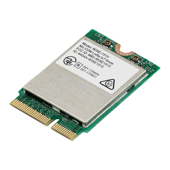
1. Product Overview 1.1. Introduction WISE-1510 is a wireless module integrated with ARM Cortex-M4 Processor and LoRa / LoRaWAN connectivity. This technology is the best solution for Low-Power Wide-Area Network (LPWAN) Applications. LoRaWAN is defined to optimize the power consumption and wide range. Your sensors or applications with low data rate requirement can be achieved years battery lifetime and kilometers long distance connection. -
Page 13: Specifications
MHF4 connector connector UART 1 (4-wire, support RTC/CTS) GPIO 1 (device only) Programming / Debug 1 via WISE-ED20 (CN1) Port 3.3V Power Operational Environment -40 ~ 85° C Temperature Operating 5% ~ 95% Relative Humidity, non-condensing Humidity WISE-1510 User Manual... -
Page 14: H/W Installation
Pin count: 75 pins Module input voltage: 3.3V DC-in Connector mating force: 30N Maximum Connector current rating: 0.5A / Power contact Connector operation temperature range: -45 °C to +85 °C Figure 1 Card Edge Bevel WISE-1510 User Manual... - Page 15 Figure 2 Card Edge Outline-Topside Figure 3 Card Edge Outline-Backside Reference from PCI Express M.2 Specification Rev 1.0 (Nov 1, 2013) Section 2.3.5 Card PCB Details WISE-1510 User Manual...
-
Page 16: Module Outline
2.3.1. Top Side Connector Physical Dimensions The top-side scheme has two connectors that share a common footprint but have different stack-up requirements. Length – 22 mm maximum including land pattern Width – 9.1 mm maximum including land pattern WISE-1510 User Manual... -
Page 17: Carrier Board Connection Length
The additional increase in length is 7.05mm maximum for top-side connector to the module length. The retention screw adds 2.75 mm maximum. The maximum extension, including land pattern, beyond the module leading edge is 4.3 mm. M2.COM module lengths are 30 mm and 42 mm. WISE-1510 User Manual... -
Page 18: Carrier Board Connector Height
The dimensions of M2.COM form factor follow the Type A 2230 -D3 M.2 module size. Hence, the carrier board connectors must choose H3.2-D3 or H4.2-D5 connector as in the following diagrams. Figure 7 H3.2-D3 Reference from PCI Express M.2 Specification, Revision 1.0, November 1, 2013 WISE-1510 User Manual... -
Page 19: Wise-1510 Pin-Out Map
2.4. WISE-1510 Pin-Out Map M2.COM STM32L443RCI6 M2.COM Signal name MCU Pin Name Signal name 3.3V USB_DP PA12 3.3V USB_DM PA11 N.C. N.C. N.C. N.C. N.C. N.C. N.C. N.C. N.C. CB_RESET_OUT# 16 N.C. N.C. CB_PWR_ON N.C. UART TX (O) N.C. Connector Key... -
Page 20: Quick Starter Of Wise-1510
Figure 8 M.2 Connector 2.5. Quick Starter of WISE-1510 2.5.1. Debug Port Connection 1. Connect debug port FPC cable to WISE-1510 debug port (CN1; on the back of PCB) 2. Connect WISE-ED20 debug board to the FPC debug cable. 3. Connect USB-to-microUSB cable from WISE-ED20 to the USB port on your PC. - Page 21 2.5.2. Debug Port Setting WISE-1510 can communicate with a host server (Windows or Linux) by using serial cables. Common serial communication programs such as Hyper Terminal, Tera Term or PuTTY can be used in this case. The example below describes the serial terminal setup using Hyper Terminal on a Windows host: 1.
- Page 22 Figure 9 Hyper Terminal Settings for Terminal Setup Figure 10 Image version is shown on terminal WISE-1510 User Manual...
-
Page 23: Development Environment Setup
3. Development Environment Setup 3.1. Overview ARM mbed is used for you to create applications running on WISE-1510. Your application code is written in C++. It uses the application programming interfaces (APIs) that mbed OS provides. These APIs allow your code to work on different microcontrollers in a uniform way. -
Page 24: Configuration
You can set the GCC ARM Embedded location via the command as below: $ mbed config --global GCC_ARM_PATH "C:\Program Files\GCC_ARM" [mbed] C:\Program Files\GCC_ARM now set as global GCC_ARM_PATH WISE-1510 User Manual... -
Page 25: Compilation
Link: xxxxx Elf2Bin: xxxxx +--------------------+--------+-------+-------+ | Module | .text | .data | .bss | +--------------------+--------+-------+-------+ | Fill 223 | 16 | 41 | | Misc | 104316 | 7804 | 5017 | | drivers 3592 | 224 | WISE-1510 User Manual... -
Page 26: Memory Layout
The timer thread that executes all the time-scheduled tasks (periodic and nonperiodic). • The stack of OS scheduler itself (also used by the ISRs). Stack checking is turned on for all threads, and the kernel will error if an overflow condition is detected. WISE-1510 User Manual... - Page 27 WISE-1510 User Manual...
-
Page 28: Partitioning
LoRa parameters, which occupies no more than 4 kilo-bytes. All user own parameters should be written into User Config partition, for which another 4 kilo-bytes are reserved. Application (Runtime image) partition is where users’ application is stored, up to 224 kilo-bytes can be used. WISE-1510 User Manual... -
Page 29: Flashing Application (Runtime Image)
Step 1: UART port connect via debug board Connect USB-to-microUSB cable from WISE-ED20 to the USB port on your Windows PC. (Red frame is reset button.) Open the corresponding COM port in serial program, ex: Tera Term. Set baud rate to 115200. WISE-1510 User Manual... - Page 30 Step 2: Runtime image upgrade mode Press ‘u’ on the PC keyboard and press reset button on ED-20 debug board. The terminal will show messages as below. Press "1" to “Download image to the internal Flash”. WISE-1510 User Manual...
- Page 31 Step 3: Start upgrading via Y modem Select the run-time image ".bin" file via Y-Modem. Waiting for run-time image transmission is complete. WISE-1510 User Manual...
- Page 32 After downloading completed, the terminal will show as below. Step 4: Reset device Press reset button on ED-20 debug board to reset device. WISE-1510 User Manual...
-
Page 33: Testing
3.8. Testing Now, you’re ready to test your WISE-1510. The sample application we created is to send sensor data every 5 seconds via LoRa if values are changed. To observe it, you can connect the debug port as described earlier. After reset WISE-1510, the result is... -
Page 34: Application Development
4. Application Development Node APIs were provided to assist user develop applications. There are 2 UART interfaces in WISE-1510. “debug_serial” is used for user development and debug. User can see debug information of sample code via debug_serial. “m2_serial” is the UART interface of M2.com. - Page 35 LoRa callback function register/status check/send data nodeApiSetTxDoneCb nodeApiSetRxDoneCb nodeApiJoinState nodeApiSendData System deep sleep (low power) mode WISE-1510 User Manual...
-
Page 36: Sample Code For Api
The detailed description of APIs can be found in /docs/html/index.html in the released SDK. 4.2. Sample Code for API If WISE-1510 was plugged in M2.com carrier board (WISE-DB1500), do below action to enable M2.com carrier board. /* Init carrier board, must be first step */ nodeApiInitCarrierBoard();... - Page 37 What you should do is Register callback function in the beginning. nodeApiSetTxDoneCb(node_tx_done_cb); nodeApiSetRxDoneCb(node_rx_done_cb); Make sure node successfully joined LoRa gateway. if(nodeApiJoinState()==0) if(join_state==2) NODE_DEBUG("LoRa is not joined.\r\n"); NODE_DEEP_SLEEP_MODE_SUPPORT nodeApiSetDevSleepRTCWakeup(1); #else Thread::wait(1000); #endif join_state=1; continue; else if(join_state<=1) node_class=nodeApiDeviceClass(); NODE_DEBUG("LoRa Joined.\r\n"); node_state=NODE_STATE_LOWPOWER; WISE-1510 User Manual...
- Page 38 NODE_ACTIVE_PERIOD_IN_SEC seconds. case NODE_STATE_LOWPOWER: if(node_class==3||node_op_mode==4) static unsigned int count=0; Thread::wait(10); if(node_state!=NODE_STATE_RX_DONE) if(count%(NODE_ACTIVE_PERIOD_IN_SEC*100)==0) if(node_op_mode!=4) node_state=NODE_STATE_ACTIVE; count++; else Thread::wait(NODE_RXWINDOW_PERIOD_IN_SEC*1000); /*Receive RX while sleep*/ if(node_state==NODE_STATE_RX_DONE) continue; else NODE_DEEP_SLEEP_MODE_SUPPORT nodeApiSetDevSleepRTCWakeup(NODE_ACTIVE_PERIOD_IN_ SEC-NODE_RXWINDOW_PERIOD_IN_SEC); #else Thread::wait((NODE_ACTIVE_PERIOD_IN_SEC-NODE_RXWIN DOW_PERIOD_IN_SEC)*1000); #endif if(node_state==NODE_STATE_RX_DONE) continue; WISE-1510 User Manual...
- Page 39 This example send sensor (Temperature, Humidity) data periodically, user should modify node_get_sensor_data() to implement read sensor data. case NODE_STATE_ACTIVE: i=0,ret=0; unsigned char frame_len=0; char frame[64]={}; frame_len=node_get_sensor_data(frame); if(frame_len==0) node_state=NODE_STATE_LOWPOWER; break; if(node_beacon_state==NODE_BCN_STATE_SPS) ret=nodeApiSendDataHighPri(NODE_ACTIVE_TX_PORT, frame, frame_len); else ret=nodeApiSendData(NODE_ACTIVE_TX_PORT, frame, frame_len); if(ret==0) NODE_DEBUG("TX: "); for(i=0;i<frame_len;i++) NODE_DEBUG("%02X ",frame[i]); NODE_DEBUG("\n\r"); WISE-1510 User Manual...
- Page 40 If LoRa node got downlink data, node_rx_done_cb() will be invoked to get data. Then transfer to NODE_STATE_LOWPOWER. case NODE_STATE_RX_DONE: if(node_rx_done_data.data_len!=0) i=0; j=0; char print_buf[512]; memset(print_buf, 0, sizeof(print_buf)); NODE_DEBUG("RX: "); for(i=0;i<node_rx_done_data.data_len;i++) NODE_DEBUG("%02X ", node_rx_done_data.data[i]); NODE_DEBUG("\r\n(Length: %d, Port%d)\r\n", node_rx_done_data.data_len,node_rx_done_data.data_port); WISE-1510 User Manual...
- Page 41 DigitalOut led(PA_8); if(node_rx_done_data.data[0]=='0') led=0; else led=1; node_state=NODE_STATE_LOWPOWER; break; The state machine transition is attached below. The detailed description of Sample code can be found in /docs/html/index.html in the released SDK. WISE-1510 User Manual...
-
Page 42: Appendix I: Node Setup Parameters
2 to 1. The other three parameters are used for OTAA, including DevEUI, AppEUI, and APPKey are set. 6. Select nodes to work with LoRaWAN or WISE Link by setting the device operating WISE-1510 User Manual... - Page 43 2.0. Here, WISE LoRaWAN, change it from 1 to 2. Link is Advantech’s proprietary LoRa MAC. WISE 7. You can select which class of Node: 1 for Class A, and 3 for Class C. (2 for Class B is reserved for future use.) Here, Class C is selected (line 207).
-
Page 44: Appendix Ii: Sensor Data Format
1 byte is required. Users are free to define their own payload field format, but only sensor data encoded according to the above format can be decoded successfully, and displayed on LoRa Dashboard on WISE-3610. WISE-1510 User Manual...
Need help?
Do you have a question about the WISE-1510 and is the answer not in the manual?
Questions and answers