Table of Contents
Advertisement
Quick Links
Advertisement
Table of Contents

Related Manuals for EFI Pro 24f


Summary of Contents for EFI Pro 24f
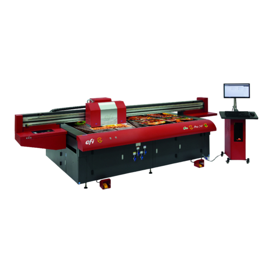
- Page 1 Pro 24f Wide Format Hybrid Printer Operations Guide...
- Page 2 The information contained in this document is confidential and proprietary to Electronics for Imaging, Inc (EFI). This information is provided only to authorized representatives of EFI and EFI customers solely for the purpose of facilitating the use of EFI’s products. No information contained herein may be disclosed to any unauthorized person for any purpose whatsoever without the prior written consent of EFI.
-
Page 3: Efi Inkjet Solutions
Mexico and South America: +1 412-690-4321 DE +49 2102 745-4500 NL +31 20 658-8080/8069 UK +44 12462-98085 Email: EuroSupport@efi.com Online Request Support Online Request Support Online Request Support https://inkjet.support.efi.com https://inkjet.support.efi.com https://inkjet.support.efi.com This document is published on-line at http://inkjet.support.efi.com. Document ID: OMM-00148 Rev. B... -
Page 4: Revision History
Revision History 11/28/2017 Released DR 4421 12/13/2017 Corrected link to Maintenance Guide on pg. 28 and returned manual name to cover page. internal... -
Page 5: Table Of Contents
3.4.5 Media Vacuum Foot Pedal ...............29 4.0 EFI Print Control Utility and EFI Pro 24f Control Window ................30 4.1 EFI Pro 24f Software Operational Overview . - Page 6 4.3.12 EFI Pro 24f Control Window “Asleep” ........
- Page 7 7.1 Use Remainder Ink ..................71 8.0 EFI Pro 24f Maintenance and Print Head Care ....................72 8.1 Maintenance Documentation .
-
Page 8: Introduction
1.0 Introduction The EFI Pro 24f Operations Guide provides an overview of the features and functions of EFI’s Pro 24f Wide Format Hybrid printer, an advanced digital printer designed to provide wide-format, full-color printing. The EFI Pro 24f uses environmentally- friendly UV-curable inks to ensure higher volume production and improved resolution over traditional silkscreen printing. -
Page 9: Customer Resources
• Training - http://inkjet.support.efi.com/training/index.php - Operator training is an essential part of printer installation and operation. EFI Inkjet Solutions provides an educational support system assisting new and experienced operators to develop and maintain skills. 1.4 Additional Support If you have any questions about your printer or other EFI Inkjet Solutions products, see http://inkjet.support.efi.com/index.php... -
Page 10: General Safety
2.0 General Safety This chapter explains how to safely use your EFI Pro 24f printer, including the access panels, shields, and warning labels, as well as how to properly handle printer inks and fluids. Before operating the printer, all personnel must: •... -
Page 11: Hazards And Precautions
2.2 Hazards and Precautions Hazards and Precautions are outlined in the following paragraphs. 2.2.1 UV Ink and Solvent Precautions Observe the following precautions regarding the printer, ink, and related solvents. • Uncured UV inks and cleaning solvents are flammable. • Uncured UV inks and cleaning solvents can cause severe eye damage. •... -
Page 12: Fire Or Explosion Risks And Precautions
2.2.8 High Voltage Dangers and Precautions The EFI Pro 24f is safe to operate in its normal operating configuration. However, with key protective covers opened or removed, electrical components carrying high voltage are exposed. The EFI Pro 24f carries high voltages that could cause serious injury or death from electrocution. -
Page 13: Efi Pro 24F Printer Overview
3.0 EFI Pro 24f Printer Overview In this chapter we describe the major assemblies and sub-assemblies of the EFI Pro 24f Wide Format printer, to familiarize you with its most important components. 3.1 Front Access This section illustrates the access panels and shields located on the front of the printer. - Page 14 3. The vacuum knife uses suction to extract excess ink from the bottom of the print heads during the sweep cycle either automatically via the EFI Pro 24f Control window or manually via the sweep button on the purge button panel. The ink is drawn into the cyclonic vacuum system.
-
Page 15: Carriage Assembly
3.1.1 Carriage Assembly The carriage assembly contains many critical components required for Inkjet printing. These components include print heads and the electronics to control them, ink tanks for the print heads, lamps for curing the ink, and a negative pressure system that controls ink flow. -
Page 16: Rear Carriage Assembly
Rear Carriage Assembly The Rear of the Carriage Assembly contains the following items: Figure 3-4: Carriage Rear View (No Covers Shown) 1 Print Head Control Board 2 Voltage Control Board 3 Overflow Tanks Document ID: OMM-00148 Rev. B... -
Page 17: Efi Pro 24F Uv Lamps
3.1.2 EFI Pro 24f UV Lamps The EFI Pro 24f is equipped with UV Lamps which provide a superior technology for ink curing. Figure 3-5: LED Lamp Detail (Right Lamp Shown) Lamp Interface Board Housing 2 Lamp Mounting Bracket Assembly Anti-static Bar Assembly Fans &... -
Page 18: Rear Access
3.2 Rear Access This section illustrates the access panels and shields located on the rear of the printer. Figure 3-6: Printer Rear Access Caution! Keep all safety interlocks, covers, and guards in place and functional. Never operate printer with covers, doors, or guards removed or with malfunctioning interlocks. - Page 19 The Ink Purge control panel provides the following manual purge functions: Figure 3-7: Ink Purge Panel 1. The left purge button controls the CYMK color ink manual purging. 2. The right purge button controls the manual purge for white. 3. The Liquid Separator button controls the cyclonic vacuum pump. Pressing this button drains the contents of the cyclonic vacuum system into the waste container Document ID: OMM-00148 Rev.
-
Page 20: Operator Station Components
3.3 Operator Station Components The Pro 24f operator’s computer components are attached to the printer’s computer compartment. Those components are: 1. A 22” flat-panel display a full-size keyboard, and a two-button wheel-mouse (Not Shown). 2. The Keyboard Tray is used to support the keyboard and mouse used for printer operation. -
Page 21: Vacuum Control
3.3.1 Vacuum Control A detail of the control valve layout is provided in Figure 3-9, below. Figure 3-9: Platen Vacuum Control Knob Layout Valve 1 Valve 2 Valve 3 Valve 4 Document ID: OMM-00148 Rev. B... -
Page 22: Cyclonic Vacuum System
3.3.2 Cyclonic Vacuum System The cyclonic vacuum system is located in the waste compartment (behind the carriage rear access panel). This compartment contains the cyclonic vacuum container, vacuum canister, and ink waste container as shown in . The design Figure 3-10 allows for the removal of most of the ink from the vacuum system before it enters the vacuum canister. - Page 23 Figure 3-12: Head Sweep Button Warning: Do NOT attempt to drain the cyclonic system (using the Liquid Separator button) and an automatic head sweep (using Head Sweep icon on the EFI Pro 24f Control window) simultaneously as this may seriously damage the printer.
-
Page 24: Printer Rear Components
3.4 Printer Rear Components This section illustrates the major components located on the rear of the printer. Figure 3-13: Printer Rear (Feed Side) Caution! Keep all safety interlocks, covers, and guards in place and functional. Never operate printer with covers, doors, or guards removed or with malfunctioning interlocks. -
Page 25: Carriage X-Axis Drive Motor Access Panel
3.4.1 Carriage X-Axis Drive Motor Access Panel The Carriage X-Axis drive motor provides the power to move the carriage via the carriage belt. This motor is located at the left end of the carriage beam (when viewing printer from the rear) and is accessed by lifting the rear door behind the operator station. -
Page 26: Energy Chain
3.4.3 Energy Chain The Energy Chain (E-Chain) is attached to the back side of the carriage and moves with the carriage when it is in motion during printing operations. The E-Chain continuously supplies the moving carriage with the following: • White Ink •... -
Page 27: Main Carriage Beam Assembly
Figure 3-16: Main Beam Carriage Main Beam Linear Encoder Strip Top Rail Bottom Rail Note: The encoder strip and rails require periodic maintenance. Refer to the Maintenance Guide (OMM-00149, EFI Pro 24f Maintenance Guide at https://inkjet.support.efi.com/doc.php?doc=4137) for details. Document ID: OMM-00148 Rev. B... -
Page 28: Media Vacuum Foot Pedal
3.4.5 Media Vacuum Foot Pedal The media vacuum foot pedal controls the media belt vacuum. With the main vacuum breaker in the on position and the vacuum control valves open, stepping on this pedal turns the vacuum motors on and creates the vacuum in the platen that holds media in place when print- ing. -
Page 29: Efi Print Control Utility And Efi Pro 24F Control Window
The EFI Pro 24f printer is operated directly using the EFI Pro 24f Print Control Utility. The system data flows as follows: Fiery XF is used to rip images to a .bco file. This file contains all the printing information and is stored on the EFI Pro 24f computer. -
Page 30: Efi Print Control Utility
The EFI Pro 24f printer is operated by using the EFI Pro 24f Print Control Utility. The printer operator imports the image source files to be printed to the EFI Pro 24f printer via a network connection in the appropriate file format (pdf, eps, etc.). -
Page 31: Print Control Utility Overview
Open and run the Print Control Utility as described in this section. Click on the Print Control Utility (PCU) icon located on the desktop. The PCU window opens. Figure 4-3: EFI Print Control Utility Overview Settings Menu Select File to Print... - Page 32 Select the Settings menu in the upper left corner of the window and select the default image folder. This opens the folder contain- ing the pre-ripped .bco files. From the default image folder, select the desired file. The PCU window displays the following (if the information is contained in the file): •...
-
Page 33: Settings Menu
4.2.2 Settings Menu The Print Control Utility Settings menu has the following options: Default Image Folder - Allows the operator to set/change the default image folder. When the user presses the “Select Files to Print” button, the default image folder is opened. The default image folder should be set to “F\XF Output”. Local Drives (C:\) - Adds or Removes other local Drives. -
Page 34: Adding Drives
4.2.3 Adding Drives The Print Control Utility “Add Drives” function operates as follows: Click on the Local Drive button. Navigate to the desired drive. and select it. Figure 4-6: Print Control Utility Select Drive Document ID: OMM-00148 Rev. B... -
Page 35: Select Files To Print Button
4.2.4 Select Files to Print Button The Print Control Utility Select File to Print menu operates as follows: Click on the button to open the file folders. Navigate to the desired file. Select the file to print. Figure 4-7: Print Control Utility Select File to Print Button Document ID: OMM-00148 Rev. -
Page 36: Move Selected Bco Option
Move Selected BCO Option If the BCO is not in route directory, for example because you are using a USB flash drive import, the system displays a prompt asking, “Would you like to copy this file to the default image folder now?” •... -
Page 37: Image Information And Ink Use Estimates Panes
4.2.5 Image Information and Ink Use Estimates Panes The Print Control image Information and Ink Usage Estimates panes display data as follows: Figure 4-9: Print Control Utility Image Information and Ink Use Estimates Displays Image information to include: • Job Name •... -
Page 38: Conflict Message
Conflict Message The previous Print Control and the Print Control Utility (PCU) cannot run together. If the previous Print Control is running, the error shown below appears when you start the PCU. If the error occurs, shut down the previous Print Control and reopen the PCU. -
Page 39: Efi Pro 24F Control Window
4.3 EFI Pro 24f Control Window The Print Control Utility launches the EFI Pro 24f Control window by clicking on the Tools button or the Adjust Image Settings button. The EFI Pro 24f Control window defines printing parameters, print options, and printer status information. -
Page 40: Carriage Controls
4.3.1 Carriage Controls The Carriage controls perform the following functions: Moves carriage up on the Z-Axis to the upper limit. Moves carriage down on the Z-Axis to the lower limit. Selectable carriage height settings. Allows the carriage to automatically set the Gap. Sets the carriage gap measurement positive distance from the Media Positive Value. -
Page 41: Movement Controls
4.3.2 Movement Controls The Movement controls the following functions: Figure 4-13: Movement Controls Moves Carriage HOME Jogs Gantry Forward Jogs Gantry Backward Moves Gantry to the Back Moves Gantry to the Middle Moves Gantry to the Front Document ID: OMM-00148 Rev. B... -
Page 42: Lamp Controls
4.3.3 Lamp Controls The Lamp Controls provide the following functions: Figure 4-14: X-Y Lamp Controls Left Lamp Control (ON/OFF) Right Lamp Control (ON/OFF) Indicates LED Lamp is curing from left to right Indicates LED Lamp is curing from right to left Note: Normally all 4 bulbs should be turned on in order to optimize curing in both directions. -
Page 43: Media Controls
4.3.4 Media Controls Media Controls provide the following functions: Figure 4-15: X-Y Media Controls Sets Media Left Edge Sets Media Width Sets Top Margin Sets Side Margin Sets Step Distance Define unit for margin measurements 4.3.5 Printer Status Bar The printer status bar displays one-line messages that detail printer status. The messages indicate what the printer is doing at any given point in time. -
Page 44: Printer Tools Bar
Test Prints - Provides a list of all the test print types. Descriptions of operator-used test print types are provided in Section 4.3.12. Print - Prints the test print selected in the Test Prints list. Controls/Ink - Opens the EFI PLC Control window described in Section 4.3.10 Parameters - Opens the Parameters window described in Section 4.3.9. -
Page 45: Printer Tests
4.3.7 Printer Tests To run printer tests, open the EFI Pro 24fControl window and select a test print from the menu and choose the Print icon to conduct that test print. Figure 4-18: Print Icon Select test in list Choose Print icon to print selected test 4.3.8 Printer Test List and Test Description... -
Page 46: Parameters Window
4.3.9 Parameters Window Click the Parameters button in the EFI Pro 24f Control window’s tool bar to open the Parameter Settings window, including the ,and System Tab Page Settings Tab Offset Tab Head Voltage Tab Head Temperatures Tab Figure 4-19: Parameters... -
Page 47: Page Settings Tab
Page Settings Tab The Page Settings tab is generally used only during printer set up. Operators are likely to use only the Carriage Height Calibration Tool (item 2). The full tab contains the following items: Modifies Media Axis. Identifies Media Position. Identifies Platform Origin. -
Page 48: Offset Tab
Offset Tab The Offset tab is generally used only by Field Service Engineers and contains the following items: Determines the type of calibration to be executed. Each selection shows different values below. Displays Print Head X Alignment Values. Displays print head R offset values. OK to save or Cancel to exit. -
Page 49: Head Voltage Tab
Head Voltage Tab The Head Voltages tab is used only by Field Service Engineers and displays the following:. Displays and sets print head voltage for each white and CYMK print head. Read button - Checks the actual voltage of the print heads and displays in the Voltage Settings fields. -
Page 50: Head Temperatures Tab
Head Temperatures Tab The Head Temperatures tab is generally used only by Field Service Engineers and contains the following items: Sets head temperatures. Set the values and choose the Set button at the bottom of the column to save the values. Displays current temperatures. -
Page 51: Control/Ink Window
4.3.10 Control/Ink window Choose the Controls/Ink button on the tool bar at the bottom of the EFI Pro 24f Control window to open the Control/Ink window. Figure 4-25: Ink System Information 1 Restores Ink Tank Temp Factory Settings (Cyan, Magenta to Supply: Fills All Secondary Ink Tanks 41°... -
Page 52: Printer Status Messages
4.3.11 Printer Status Messages During printing operations, the EFI Pro 24f displays Printing In Progress status updates. These messages provide data on the following: • Job Status • Lamp Status • Temperature and Vacuum Status • Printer Status • Printer Control... -
Page 53: Efi Pro 24F Control Window "Asleep
4.3.12 EFI Pro 24f Control Window “Asleep” When the printer is put into sleep mode, the EFI Pro 24f Control window becomes grayed-out. A moon icon appears in place of the normal sun icon, and the window does not operate until placed back into the “awake” mode. This is accomplished by clicking the moon icon to wake the system. -
Page 54: Efi Pro 24F Printer Setup
5.0 EFI Pro 24f Printer Setup This chapter describes set-up procedures for the EFI Pro 24f Wide Format Printer. Perform the tasks in this chapter when setting up the EFI Pro 24f Wide Format printer for operation. 5.1 Full Printer Startup From Power Down... -
Page 55: Printer Startup From Sleep Mode
2. On the PCU window, launch the EFI Pro 24f Control window and click the “Moon” icon. The EFI Pro 24f Control window lights up and the “Sun” replaces the moon icon. The printer is now in “Awake” mode. Allow 2-3 minutes for print heads to come to the required temperature and the ink pumps to fill the secondary tanks before printing. -
Page 56: Set Media Vacuum Chamber Controls
5.3 Set Media Vacuum Chamber Controls Open the vacuum valves for the desired chambers. Use vacuum only for chambers covered by the media and close vacuum valves for all other chambers. Figure 5-2: Platen Vacuum Control Knob Layout Valve 1 Valve 2 Valve 3 Valve 4... -
Page 57: Printing On The Efi Pro 24F
6.0 Printing on the EFI Pro 24f This chapter covers the process for printing on the EFI Pro 24f, including the steps for standard print jobs, conducting a daily white print, printer workflows, full-bleed printing, centering a print on the media, skipping blank space to increase print speeds, and methods for printing multiple rigid media boards. -
Page 58: Verify Lamp Settings
Figure 6-2: EFI PLC Control Window - LED Lamps Box 2. Click any light bulb that isn’t yellow, to toggle it to yellow/on. 3. In the toolbar at the bottom of the EFI Pro 24f Control window, choose the Controls/Ink button to open the EFI PLC Control win- dow. -
Page 59: Set The Carriage Gap
6.1.3 Set the Carriage Gap 1. In the EFI Pro 24f Control window’s Carriage box, click the Set Gap button. The printer carriage raises in home zone, advances over the media, lowers to measure the media thickness, and then returns to the home zone. -
Page 60: Purge And Sweep Print Heads
1. From the EFI Pro 24f Control screen, choose the Purge White icon to white print heads. The system automatically follows this up with a head sweep. 2. b. From the EFI Pro 24f Control screen, choose the Purge Color icon to purge the CMYK print heads. The system automatically fol- lows this up with a head sweep. -
Page 61: Perform Nozzle Checks
6.1.5 Perform Nozzle Checks The Nozzle Check test provides a test print that shows whether all print heads are firing properly. Perform a Nozzle Check prior to commencing printer operations to ensure all print heads are firing properly. Figure 6-8: Nozzle Check Selection Figure 6-9: Nozzle Check Test Print Document ID: OMM-00148 Rev. - Page 62 Figure 6-10: Nozzle Check Test Print Comparison Document ID: OMM-00148 Rev. B...
-
Page 63: Set Margins
6.1.6 Set Margins 1. In the Media box (middle right), set the Top Margin and the Side Margin. Note: Top Margin adds white space above print, advancing the media further before printing. Side Margin adds white space to the left of the print. Figure 6-11: Test Prints List and Print Button Top Margin Setting Side Margin Setting... -
Page 64: Print File From Efi Print Control Utility
6.2 Print File from EFI Print Control Utility 1. Click the Close button on the EFI Pro 24f Control window to return to the EFI Print Control Utility 2. Click the “+” (plus) folder button to load the file to print. (See Figure 6-12.) -
Page 65: Print Workflows
The charts below contain several work flows that EFI has found useful in day to day operation of the EFI Pro 24f printers. Note: Different printer modes have different intended viewing distances for the printed output. In general, the faster output speeds are intended to be used in creating prints that are viewed from larger distances. -
Page 66: Workflows In Fiery Xf
Workflows set up in the Fiery XF software appear as in the image below: Users Workflows Help menu; Help docs and supplemental knowledge database Output Devices can also be accessed at: http://help.efi.com/fieryxf/ Output Configuration options http://help.efi.com/fieryxf/KnowledgeBase/index.html Document ID: OMM-00148 Rev. B... -
Page 67: Skip Blank Space During Prints
6.4 Skip Blank Space During Prints The Skip Blank Space feature enables the EFI Pro 24f printer to advance media quickly through blank spaces in an image or in a group of nested or step-and-repeat images. With Skip Blank Space enabled, the printer quickly advances the media through blank spaces, in order to provide faster printing. -
Page 68: Sample Images
6.4.1 Sample Images Note that the following images include one with a white fill background and one with true blank space (represented by check boxes) that runs the full width of the image. Figure 6-14: Image With White Field/White Fill Figure 6-15Image With Blank Space/White Space Rows of Blank Space Running Checked Background... -
Page 69: Procedures For Replenishing Ink
7.0 Procedures for Replenishing Ink This chapter describes basic ink replenishing procedures for the EFI Pro 24f Wide Format Printer. Carefully remove the ink container cap and ensure that no ink spills into the ink supply compartment. Note: It may be necessary to clean the tubes and float connected to the cap. -
Page 70: Use Remainder Ink
7.1 Use Remainder Ink When an installed ink bottle level gets to half full, you can transfer remainder ink from a carefully stored bottle to refill the installed bottle. Important! Check the expiration date on the old bottle. Do not use if it is past the expiration date. 1. -
Page 71: Efi Pro 24F Maintenance And Print Head Care
8.0 EFI Pro 24f Maintenance and Print Head Care This chapter contains descriptions of some key maintenance procedures that operators are required to perform on the EFI Pro 24f Wide Format Printer. Complete descriptions of the maintenance items are provided in the Maintenance Guide (OMM-00149 24f Maintenance Guide). -
Page 72: Print Head Care
8.2 Print Head Care Print head care for the EFI Pro 24f printer is limited. The print heads should function properly at all times if they are kept clean and properly bled of any air that might enter the print head. To ensure proper operation of print heads, follow the print head care procedure defined below: 8.2.1 Bleeding Print Heads... - Page 73 6. Using the special bleed valve tool (P/N 45117492), open the bleed valves, press the Purge button, and bleed print heads one at a time. 7. Allow the ink to run until it shows no sign of air bubbles. Ink runs into the trough and down into the cyclonic vacuum system. 8.
-
Page 74: Ink Purge Procedures
The print heads should be purged and a head sweep should be performed in one of two ways: a. From the EFI Pro 24f Control screen, choose the Purge White icon to white print heads. The system automatically follows this up with a head sweep. -
Page 75: Clean Print Heads
Print Heads should be cared for and cleaned at the end of each shift or after each 8 hours of printer operation, to remove any ink that is curing on the heads. 1. Use the Up arrow on the EFI Pro 24f Control screen to raise the carriage. Up Arrow 2. - Page 76 4. Fold a lint-free wipe in quarters and saturate with clean flush. Then reach under the carriage print head plate to locate the back of the print head to be cleaned. 5. Align two fingers with the bottom of the print head and press gently against the head.
-
Page 77: Efi Pro 24F Sleep Mode/Shutdown Procedures
9.0 EFI Pro 24f Sleep Mode/Shutdown Procedures This chapter describes EFI Pro 24f Wide Format Printer sleep and shutdown procedures for the overnight, short term (1 - 3 days), and long term (4+ days). Those procedures are described in the sections that follow: 9.1 Overnight Sleep Mode... -
Page 78: Re-Wake Printer
Note: When suspending print operations for the night or the weekend, perform daily maintenance procedures prior to shutdown. See the EFI Pro 24f Maintenance Guide (at https://inkjet.support.efi.com/doc.php?doc=3753) for daily maintenance procedures. Figure 9-1: EFI Pro 24f Control Screen Printer Mode (Asleep/Awake) Icon “Moon”... -
Page 79: Short-Term Printer Shutdown
1. Power off the media vacuum blower using the switch located in the computer compartment of the printer. 2. Ensure that the EFI Pro 24f Control screen has been closed. 3. Turn off both the CMYK and white negative pressure valves located on the top left side of the carriage. This prevents the ink from dripping from the heads while the power is off. -
Page 80: Long-Term Printer Shutdown
It may be necessary to power off the printer for longer periods of time when it won’t be in use. Use the long-term shutdown procedure when shutting the printer down for 4 or more days.Power off the printer only when necessary. 1. Use the EFI Pro 24f Control screen to raise the carriage. -
Page 81: E-Stop Conditions
9.4 E-Stop Conditions Emergency stops are installed at each end of the EFI Pro 24f printer. These should be used only when there is an emergency condition. E-Stops should not be used to shut off the machine under normal conditions. -
Page 82: Power Outages
9.5 Power Outages If power outages occur frequently at the printer site, it is advisable to install a UPS system. The UPS system must be installed on the main power to the printer and must conform to Printer Power Requirements. 9.5.1 Power Outage During Printing 1.
Need help?
Do you have a question about the Pro 24f and is the answer not in the manual?
Questions and answers