Table of Contents
Advertisement
Quick Links
Advertisement
Table of Contents

Related Manuals for EFI T1000


Summary of Contents for EFI T1000
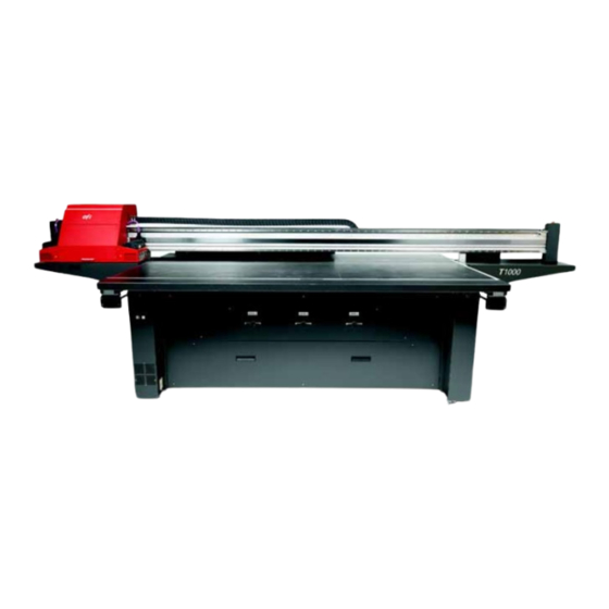
- Page 1 Basic Operator’s Guide _____________ T1000 Printer...
- Page 2 Imaging, Inc (EFI). This information is provided only to authorized representatives of EFI and EFI customers solely for the purpose of facilitating the use of EFI’s products. No information contained herein may be disclosed to any unauthorized person for any purpose whatsoever without the prior written consent of EFI.
-
Page 3: Efi Inkjet Solutions
EFI Inkjet Solutions United States One VUTEk Place Meredith, New Hampshire 03253 USA 603-279-4635 603-279-6411 Technical Support, 24 Hours 603-677-3111 http://w3.efi.com/Vutek/Products http://w3.efi.com/WideFormat/Products Europe/Middle East Ikaros Business Park Ikaroslaan 9 B-1930 Zaventem, Belgium 1930 32.2.749.9420 32.2.749.9465 Internet Support http://www.vuteksupport.com http://www.rasteksupport.com/ This document is published online at http://www.vuteksupport.com/... -
Page 4: Table Of Contents
Introduction ......................6 Customer Support Web Site ................. 6 Customer Reference Guides (Site Prep and Installation Guides)......... 6 Printer Safety Guide (EFI Family of Products) ............6 General Safety ......................7 Print Carriage Motion Warnings ................7 Printer-specific Safety .................... 7 Carriage Drive Belt ..................... - Page 5 Maintenance Guide ....................54 Vacuuming the Surface of the Jet Packs..............54 Recovering Print Heads ..................57 Shutdown Procedures ..................... 58 Shutdown and Storage Guidelines ................. 58 Standby - Overnight .................... 58 Restarting from an Emergency Stop............... 58 Index ........................60 EFI, Inc.
-
Page 6: Introduction
Congratulations! You have purchased the finest wide format digital ink jet printing system in the world. EFI T1000 printers are premium digital ink jet printers with vivid full color and white printing on a variety of sheet media. EFI wants you to get the best possible images from your printer, and wants your printing experience safe and profitable. -
Page 7: General Safety
General Safety This chapter describes how to safely use your EFI T1000 printer. Please review and adhere to all safety precautions and attend a Basic Operator Training Class before operating the printer. Introduction Before operating this printer, please read and understand the EFI Ink Jet Printer Safety Guide, http://www.vuteksupport.com/doc.php?doc=683... -
Page 8: Restarting After An Emergency Stop
The emergency stop push buttons are for your personal safety, well avoid printer damage during extraordinary circumstances. Restarting after an Emergency Stop If an e-stop is pressed, follow the instructions in Restarting from an Emergency Stop. EFI, Inc. - Page 9 Electronics cover, left side of printer Carriage Drive Belt/E-Stop cover Ink or Solvent Emergencies If an emergency situation involving inks or solvents arises, contact local emergency services and have a copy of the MSDS available for emergency service personal. EFI, Inc.
- Page 10 The printer's UV Lamps emit UV light during printing. Note: UV light exposure is hazardous to eyes and skin. Please observe all safety precautions when servicing printer components. Operators are required to read, understand, and sign the UV Safety Acknowledgement form at: http://www.vuteksupport.com/doc.php?doc=1033 EFI, Inc.
-
Page 11: Printer Overview
The following sections indicate the location of basic printer components referenced in this guide. Front View The Operator Station side is the Front of the printer Figure 4: T1000 Printer – Front View Carriage Assembly Gantry* Carriage Beam Assembly Umbilical Assembly... -
Page 12: Rear View
Rear View The following paragraphs and figures describe the compartments and/or components on the rear and sides of the T1000 Printers Figure 5: T1000 Printer – Rear View Gantry drive motors (2) Carriage assembly Ink bottles Umbilical Assembly Vacuum motor cover... -
Page 13: Electrical Configuration
Electrical Configuration This section contains the recommended printer electrical configuration. Figure 6: Printer Electrical Configuration Blower AC Adaptor Carriage Monitor and Computer Auxiliary power strip for Monitor and CPU USB Connection Dedicated 230V UPS (Optional) – 115V EFI, Inc. -
Page 14: Main Ac Breaker
Safety Guide, for complete safety information relating to electrical power. Figure 7: Main AC Breaker – On position Auxiliary Power Switch The Auxiliary Power Switch controls power to the printer components. Figure 8: Auxiliary Power Switch – On position EFI, Inc. -
Page 15: Carriage Assembly Components
The Carriage Assembly is comprised of the following components. Detailed descriptions are in subsequent sections. Figure 9: Carriage Assembly Components Carriage lift knob UV Lamps Print head cover Purge tray (waste) cover Lamp lift screw or adjustable lamps EFI, Inc. -
Page 16: Uv Lamp Height Adjustments
UV Lamp Height Adjustments T1000 printers contain two possible UV Lamp Adjustment mechanisms: a screw adjustment or a three level adjustment plate. Figure 10: UV Lamp Height Adjustment mechanisms Screw adjustment Three level plate adjustment plate Carriage Assembly – Interior The Carriage Assembly –... -
Page 17: Print Head Layout
Figure 13: Ink Bottles and Ink Pumps Set of ink and vacuum pumps White ink bottles White ink recirculation line Cyan ink bottle Magenta ink bottle EFI, Inc. - Page 18 Yellow ink bottle Black ink bottle Ink filter EFI, Inc.
- Page 19 Figure 14: Electronics and Power Distribution Cabinet, cover removed Power supply Power supply USB Hub Main AC Power connection USB power supply UV Lamp Ballast Right UV Lamp Ballast Left Printer Interface board Servo controller, Y axis Servo controller, X Axis Servo controller, Carriage EFI, Inc.
-
Page 20: Usb Hub
Negative Pressure Backup System The T1000 ships with a 24V adaptor that connects to an auxiliary jack on the printer and provides dedicated power to the carriage vacuum system. The T1000 negative pressure system prevents ink from dripping from the print nozzles. Insufficient negative pressure can result in ink dripping and excessive negative pressure can result in ink starvation during printing. -
Page 21: Ups Battery Backup
The printer contains separate AC power outlets for computer and printer components. The T1000 contains an auxiliary AC power outlet for supplying AC power only to the printer control computer and monitor, or optionally, a UPS if the computer and monitor are also to be powered from the UPS. - Page 22 Table Vacuum Pump Power Connection The T1000 ships with a vacuum pump that holds media against the media table during printing. The vacuum pump plugs into the receptacle provided on the inside right rear of the printer base assembly.
- Page 23 The Vacuum Pump is located underneath the printer behind the lower rear cover. Figure 19: Vacuum Pump Vacuum Table Switches There are three Vacuum Table Switches allowing the user to control the three Vacuum Table Zones. Figure 20: Vacuum table switches, “On” position EFI, Inc.
-
Page 24: Vacuum Table Zones
Vacuum Foot Pedal Control Press the foot pedal at the front of the printer to toggle vacuum media table on and off. Figure 22: Vacuum Foot Pedal The foot pedal connects at the inside base of the front left printer leg. EFI, Inc. -
Page 25: Carriage Encoder Strip And Read Head
The gantry encoder strip and read head provide gantry location information to the printer. The encoder strip and read head are located on the left and right sides of the Vacuum table. Figure 24: Gantry Encoder Strip and Read Head (left); Encoder strip, view from below Read head Encoder Strip EFI, Inc. -
Page 26: Data Communications System
Data Communications System The T1000 data communications system is comprised of numerous printed circuit board assemblies (PCBs), each serving a unique function. A flow diagram of the T1000 communication network is provided next. Figure 25: Data Communications System overview... - Page 27 Ink Heater Control PCBA Servo Power PCBA USB Hub Converter Print Heads Print Head Control PCBA FPGA PCBA Iris Motion I/O PCBA Galil PCBA Servos 1, 2, and 3 Right Gantry Motor Left Gantry Motor Carriage Motor Computer/CPU EFI, Inc.
-
Page 28: Initial Printer Setup
If the PC AC power is not connected via the dedicated outlet on the printer, some power is available to the T1000 printer through its USB connection. In this case, for a complete power down, the computer must be turned off and the USB cable must be disconnected. -
Page 29: Start The Printer Application Software
After the printer control computer has finished its login routine, start the printer software using the following instructions. 1. Double-click the T1000 icon to launch the T1000 printer control program. 2. The control program will open to the Print tab menu as the default screen. -
Page 30: Loading Media
For easiest access to media table when loading media, send the carriage and gantry to Home position. 1. Stand in front of the T1000 and load the media with its top-left corner positioned in the front-right corner of the vacuum table. Proper orientation and placement of the media is very important, especially when printing on position-dependent materials. -
Page 31: Vacuum Table
Proper carriage height adjustment ensures the finest dot quality and prevents damage to the print heads during printing due to head strikes. The T1000 includes a set of adjustment tools for checking and setting the print carriage height prior to running a print. - Page 32 2. Gently push the carriage, by hand, over the print media. Note: For consistency, use the same position each time you are verifying the carriage head height. Figure 31: Carriage Height tool over media 3. Slide the carriage height gap tool under the carriage between the UV Lamps. EFI, Inc.
- Page 33 Figure 33: Carriage height adjustment knob directions 6. With the carriage height properly set, the operator can proceed to Performing Print Head Maintenance. EFI, Inc.
-
Page 34: Performing Print Head Maintenance
Additional maintenance is required for customers who have installed the T1000 in a dry and/or dusty environment. Each of the six print heads on the T1000 Printer has 304 individual print nozzles for precisely delivering ink to the print media. -
Page 35: T1000 Control Program
T1000 Control Program This chapter covers the T1000 Control Program, or GUI (Graphical User Interface.) GUI – Print tab Set print options in the Print tab. The Print tab controls printing, print options, such as layout, location, number of copies, and printer status information. - Page 36 “ISI” file extension for full color job and an “ISM” file extension for colors + white Horizontal gap – Horizontal (x-axis) distance in inches between multiple copies Horizontal copies – Number of copies to print in the horizontal direction Horizontal offset – Distance in inches from (0, x) EFI, Inc.
-
Page 37: Gui - Motion Tab
Home carriage – Send Carriage to Home position Home Gantry – Send Gantry to Home position Send Carriage to Absolute Position; location carriage moves based on (x, 0) Send Gantry to Absolute Position; location gantry moves based on (0, y) EFI, Inc. -
Page 38: Gui - Tending Tab
Water In Temp (read only) Vacuum Set Water Out Temp (read only) Head Temp Set Head Info table Tank Info table Both Channels 39 Volt supply, +/- volts from 39 Left Lamp Status Printer status messages – Tending tab Right Lamp Status EFI, Inc. -
Page 39: Gui - Maintenance Tab
Bleed Purge White button – Click to start a three second purge of the selected white channel Run Pump button – NOT USED Start Emptying White – Begins emptying the white secondary ink tank Cancel Emptying White – NOT USED EFI, Inc. -
Page 40: Gui - Service Tab
Inexperienced users performing these tasks could disable the printer, rendering it unusable. Note: Image cropped for illustrative purposes. Profile Carriage Controller Voltages Profile Gantry button Calibrate Carriage Reset Heater Board Update Motion Controller Firmware Printer status messages – Service tab EFI, Inc. -
Page 41: Lamp Operation Modes
Caution! A maximum lamp cure setting (100% + low physical lamp placement) may cause media to buckle upward. This is the primary cause of the carriage running into the media, damaging print heads. Print heads damaged in this manner are not covered under any warranty. EFI, Inc. -
Page 42: Printer Operation
Printing Overview Follow these basic steps to print an image from the T1000 printer. 1. Open an Image file and prepare the file for RIP. 2. Select the Image Profile. -
Page 43: Start Print
For optimum printing results, follow these guidelines when printing with White ink. White UV ink is very heavy and pigments tend to settle out of the ink. The T1000 uses a recirculation pump to keep the white ink in the main ink bottle stirred. However, white ink still sits in many parts of the printer including tubing, the working reservoirs, and the two white print heads. - Page 44 1. To prepare the image for printing, the RIP must be instructed to generate the white color plane. 2. After ripping the file as required, import the ISW file into the Print Control Program. 3. From the GUI, select the Quality/White coverage, Figure Figure 39: White Quality and Coverage EFI, Inc.
-
Page 45: Printer Tests
Preparing for Printer Tests Accurate print head alignment is critical on the T1000 to ensure high quality image output. Note: Proper print head alignment can only be achieved with the T1000 printer at operating temperature. Prior to performing any printer test, the printer must be fully functional. -
Page 46: Printing And Analyzing A Nozzle Test
3. Set both the Horizontal Offset and the Vertical Offset values to position the test image in the desired location. If this is a new piece of media, begin at (0, 0) inches. 4. Click the Print Nozzle Test button. A single pass nozzle test prints. EFI, Inc. -
Page 47: Additional Alignment Procedures
Note: Do not attempt to change any Alignment values until you have printed an acceptable Nozzle Test. Additional Alignment Procedures The instructions for the remaining alignment procedures are located on the EFI Support website. 1. Proceed to the website at http://www.vuteksupport.com. -
Page 48: Ink Care Procedures
Replacing Ink Bottles Follow these instructions when replacing ink bottles. The T1000 is equipped with an Ink Low alert screen which displays in the GUI. Do not replace ink until the Ink Low alert screen displays. Note: UV Curable Ink can be stored for a maximum of six months. Using ink beyond its shelf life will cause printing problems. -
Page 49: Cmyk Inks
3. Check the expiration date on your new bottle of ink to ensure the new bottle is still usable. The T1000 Inks can be replenished while the printer is printing. However, EFI recommends replenishing the inks while the T1000 printer is idle and gantry is in Home position. CMYK Inks... -
Page 50: Ink Purge Process
However, great care must be taken during blotting to avoid pushing debris up into the print nozzles. Note: EFI recommends using the vacuum cleaning method over blotting. T1000 printer operators will find vacuum cleaning increases reliability and print nozzle up-time. -
Page 51: Emptying Waste Pan
Empty the tray if it is more than 50-75% full. 1. From the GUI, go to the Motion tab and click Park Carriage to position the carriage over the waste tray compartment. EFI, Inc. - Page 52 4. Slowly remove the waste pan and pour contents into the waste container. Figure 44: Waste pan 5. Replace the waste pan and close the waste pan door. 6. Dispose of the waste inks in accordance with local site requirements. EFI, Inc.
- Page 53 From the GUI, click the Maintenance tab. 2. In Ink Management pane, change the Tank drop-down to White. 3. Check or clear the Enable Recirculation check box to turn the recirculation system on or off, respectively, and save changes. Figure 45: White ink recirculation EFI, Inc.
-
Page 54: Maintenance And Jet Pack Care
The Maintenance Guide provides you with a list of preventative maintenance procedures. See http://www.vuteksupport.com/doc.php?doc=1800. Safety Guide Before working with any EFI-VUTEk printer, review all safety precautions and procedures in the Safety Guide, http://www.vuteksupport.com/doc.php?doc=683. Before You Begin Before beginning any maintenance procedures, verify that you have all the materials required to complete the procedure. - Page 55 7. Carefully insert the vacuum wand with the slot oriented towards the print heads and hold it flat against the bottom of the print head mounting plate. EFI, Inc.
- Page 56 However, great care must be taken during blotting to avoid pushing debris up into the print nozzles. EFI recommends using the vacuum cleaning method over blotting. T1000 printer operators will find vacuum cleaning results in a more thorough cleaning of the heads with a shorter recovery time.
-
Page 57: Recovering Print Heads
0.5 difference, there may be problems with the 3. To change the Vacuum Set value, click in the field, type in a new value and press the Enter button. Note: Vacuum settings will vary depending on printer environment and elevations. EFI, Inc. -
Page 58: Shutdown Procedures
15. Log on to the printer computer and launch the printer GUI. 16. From the Service tab, click the Home Gantry button. 17. The T1000 printer power is now restored. 18. Print an acceptable Nozzle test. 19. Restart the print job. - Page 59 Figure 50: USB connection and Main Power Breaker USB Connection Main breaker EFI, Inc.
-
Page 60: Index
Index Additional Alignment Procedures, 47 Additional Support, 6 Adjusting Carriage Height, 31 Auxiliary Outlet for Printer Control Computer and Monitor, 21 Auxiliary Power Switch, 14 Basic White Printing, 43 Before You Begin, 54 Bi Lamp Mode, 41 Bleed Purge Process, 50 Bleeding Air from Print Heads, 34 Carriage Assembly –... - Page 61 Print Head Alignment Procedures, 45 Print Head Layout, 17 Print Head Warm Up, 29 Printer and Computer Startup, 28 Printer Safety Guide (EFI Family of Products), 6 Printer-specific Safety, 7 Printing an Image, 42 Printing an Image File, 42 Printing and Analyzing a Nozzle Test, 46...
- Page 62 Start the Printer Application Software, 29 Storing Ink, 48 Table Vacuum Pump Power Connection, 22 Training, 6 Uni Lamp Mode, 41 UPS Battery Backup, 21 USB Hub, 20 Using Your Maintenance Log, 54 UV Lamp Height Adjustments, 16 UV Light Exposure, 10 Vacuum Foot Pedal Control, 24 Vacuum Table, 31 Vacuum Table Zones, 24...
- Page 63 Auto-Count, BioVu, ColorWise, Command WorkStation, Digital StoreFront, DocBuilder, DocBuilder Pro, DocStream, EDOX, the EFI logo, Electronics For Imaging, Fabrivu, Fiery, the Fiery logo, Fiery Driven, the Fiery Driven logo, Inkware, Jetrion, MicroPress, OneFlow, PressVu, Printellect, PrinterSite, PrintFlow, PrintMe, PrintSmith Site, Prograph, RIP-While- Print, Ultravu and VUTEk are registered trademarks of Electronics for Imaging, Inc.
Need help?
Do you have a question about the T1000 and is the answer not in the manual?
Questions and answers