Table of Contents
Advertisement
Quick Links
Advertisement
Table of Contents

Related Manuals for KTM 1290 SUPER ADVENTURE R 2018


Summary of Contents for KTM 1290 SUPER ADVENTURE R 2018
- Page 1 OWNER'S MANUAL 2018 1290 Super Adventure R Art. no. 3213753en...
- Page 3 DEAR KTM CUSTOMER Congratulations on your decision to purchase a KTM motorcycle. You are now the owner of a state-of-the-art DEAR KTM CUSTOMER sports motorcycle that will give you enormous pleasure if you service and maintain it properly. We hope you enjoy riding this motorcycle! Please enter the serial numbers of your vehicle below.
- Page 4 Reproduction, even in part, as well as copying of all kinds, is permitted only with the express written permission of the copyright owner. ISO 9001(12 100 6061) According to the international quality management standard ISO 9001, KTM uses quality assur- ance processes that lead to the maximum possible quality of the products. Issued by: TÜV Management Service KTM Sportmotorcycle GmbH Stallhofnerstraße 3...
-
Page 5: Table Of Contents
TABLE OF CONTENTS VIEW OF VEHICLE ........22 TABLE OF CONTENTS MEANS OF REPRESENTATION ....11 View of vehicle, front left (example) ... 22 Symbols used ........11 View of vehicle, rear right Formats used........12 (example)........24 SAFETY ADVICE.......... 13 SERIAL NUMBERS ........ - Page 6 Side stand........54 7.23 Quick Selector 2 display ....77 6.32 Center stand........55 7.24 Navigation‑Display (optional)..... 78 7.25 Menu..........79 COMBINATION INSTRUMENT ..... 56 7.25.1 KTM MY RIDE (optional) ....79 Combination instrument ....56 7.25.2 Audio (optional)......80...
- Page 7 TABLE OF CONTENTS 7.25.3 Navigation (optional) ....82 7.25.28 ABS.......... 109 7.25.4 Navigation setup (optional) ... 83 7.25.29 HHC (optional) ......111 7.25.5 Navigation information 7.25.30 Settings ........111 (optional) ........85 7.25.31 Favourites ......... 112 7.25.6 Volume (optional) ......86 7.25.32 Navigation Info Screen ....
- Page 8 TABLE OF CONTENTS Adjusting the handlebar 10 RIDING INSTRUCTIONS......148 position ........127 10.1 Checks and maintenance measures Adjusting the windshield ....130 when preparing for use ....148 Adjusting the basic position of the 10.2 Starting......... 149 clutch lever ........131 10.3 Starting off........
- Page 9 TABLE OF CONTENTS 12.4 Adjusting the spring pretension of 13.9 Checking the chain, rear sprocket, the fork......... 178 and engine sprocket ....... 193 12.5 Compression damping of the shock 13.10 Checking/correcting the fluid level absorber........179 of the hydraulic clutch....196 12.6 Adjusting the low-speed 13.11 Checking the steering head bearing...
- Page 10 TABLE OF CONTENTS 14 BRAKE SYSTEM ........225 16 ELECTRICAL SYSTEM ....... 259 14.1 Antilock brake system (ABS) ... 225 16.1 Daytime running light (DRL)..... 259 14.2 Checking the brake discs ....228 16.2 Cornering headlight ......260 14.3 Checking the brake fluid level of 16.3 Removing the battery ....
- Page 11 TABLE OF CONTENTS 19 SERVICE WORK ON THE ENGINE ....289 23.6 Tires ..........323 23.7 Fork..........323 19.1 Checking the engine oil level... 289 23.8 Shock absorber ......324 19.2 Changing the engine oil and oil 23.9 Chassis tightening torques ....326 filter, cleaning the oil screens ..
- Page 12 TABLE OF CONTENTS INDEX ............. 350...
-
Page 13: Means Of Representation 1
All work marked with this symbol requires specialist knowledge and technical understanding. In the interest of your own safety, have these jobs performed by an authorized KTM workshop! Your motorcycle will be optimally cared for there by specially trained experts using the auxiliary tools required. -
Page 14: Formats Used
1 MEANS OF REPRESENTATION Indicates a voltage measurement. Indicates a current measurement. Indicates the end of an activity, including potential rework. Formats used The typographical formats used in this document are explained below. Proprietary name Indicates a proprietary name. Name ®... -
Page 15: Safety Advice 2
SAFETY ADVICE 2 Use definition – intended use The vehicle is designed and constructed to withstand the usual demands of regular traffic and use on gentle ter- rain (unpaved roads). This vehicle is not suitable for use on race tracks. Info This vehicle is only authorized for operation on public roads in its homologated version. -
Page 16: Degrees Of Risk And Symbols
2 SAFETY ADVICE Info Various information and warning labels are attached in prominent locations on the model described. Do not remove any information or warning labels. If they are missing, you or others may not recognize dangers and may therefore be injured. Degrees of risk and symbols Danger Indicates a danger that will immediately and invariably lead to fatal or serious permanent injury if the... -
Page 17: Tampering Warning
SAFETY ADVICE 2 Tampering warning Tampering with the noise control system is prohibited. Federal law prohibits the following acts or the causing thereof: 1 The removal or rendering inoperative by any person other than for purposes of maintenance, repair, or replace- ment, of any device or element of design incorporated into any new vehicle for the purpose of noise control prior to its sale or delivery to the ultimate purchaser or while it is in use, or 2 the use of the vehicle after such device or element of design has been removed or rendered inoperative by any... - Page 18 The vehicle should only be used by trained persons. An appropriate driver's license is needed to ride the vehicle on public roads. Have malfunctions that impair safety promptly eliminated by an authorized KTM workshop. Adhere to the information and warning labels on the vehicle.
-
Page 19: Protective Clothing
– Always wear protective clothing that is in good condition and meets the legal regulations. In the interest of your own safety, KTM recommends that you only operate the vehicle while wearing protective clothing. Work rules Special tools are necessary for some of the work. -
Page 20: Environment
Because motorcycles are not subject to the EU regulations governing the disposal of used vehicles, there are no legal regulations that pertain to the disposal of an end-of-life motorcycle. Your authorized KTM dealer will be glad to advise you. -
Page 21: Important Notes 3
IMPORTANT NOTES 3 Warranty The work specified in the service schedule may only be performed in an authorized KTM workshop and must be recorded in both the Service & Warranty Booklet and in KTM Dealer.net, otherwise any warranty coverage will become void. -
Page 22: Service
Please follow the instructions in the text. Customer service Your authorized KTM dealer will be happy to answer any questions you may have on your vehicle and KTM. - Page 23 IMPORTANT NOTES 3 A list of authorized KTM dealers can be found on the KTM website. International KTM Website: http://www.ktm.com...
-
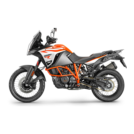
Page 24: View Of Vehicle
4 VIEW OF VEHICLE View of vehicle, front left (example) S02250-10... - Page 25 VIEW OF VEHICLE 4 Socket for electrical accessories ( p. 44) Clutch lever ( p. 30) Seat lock ( p. 49) Grab handles ( p. 50) Luggage rack plate ( p. 50) Passenger footrest ( p. 52) Center stand ( p.
-
Page 26: View Of Vehicle, Rear Right (Example)
4 VIEW OF VEHICLE View of vehicle, rear right (example) S02251-10... - Page 27 VIEW OF VEHICLE 4 Filler cap Combination switch, left side ( p. 31) Fork compression adjuster Combination switch, right ( p. 38) Fork rebound adjustment Hand brake lever ( p. 30) Storage compartment Cooling system compensating tank Foot brake lever ( p.
-
Page 28: Serial Numbers
5 SERIAL NUMBERS Chassis number The chassis number is stamped on the bottom right of the frame behind the steering head. The chassis number is also shown on the type label. 402294-10 Type label Type label is affixed to the top left of the frame behind the steering head. -
Page 29: Key Number
SERIAL NUMBERS 5 Key number The key number Code number can be found on the KEYCODECARD. Info You need the key number to order a spare key. Keep the KEYCODECARD in a safe place. F01249-10 Engine number The engine number is stamped on the right side of the engine. -
Page 30: Fork Part Number
5 SERIAL NUMBERS Fork part number The fork part number is stamped on the inner side of the fork stub. 402295-10 Shock absorber article number The shock absorber article number is stamped on the top of the shock absorber above the adjusting ring towards the engine side. -
Page 31: Steering Damper Article Number
SERIAL NUMBERS 5 Steering damper article number Steering damper article number is embossed on the underside of the steering damper. H02023-10... -
Page 32: Controls
6 CONTROLS Clutch lever The clutch lever is fitted on the left side of the handlebar. The clutch is hydraulically operated and self-adjusting. K00797-10 Hand brake lever The hand brake lever is fitted on the right side of the handle- bar. -
Page 33: Throttle Grip
CONTROLS 6 Throttle grip The throttle grip is fitted on the right side of the handlebar. K00798-11 Combination switch, left side The left combination switch is fitted on the left side of the handle- bar. -
Page 34: Light Switch
6 CONTROLS Overview of the left combination switch Light switch ( p. 32) Cruise control system tip switch ( p. 33) Menu switch ( p. 36) Turn signal switch ( p. 36) Horn button ( p. 38) F00882-10 Light switch The light switch is fitted on the combination switch on the left. -
Page 35: Cruise Control System Tip Switch
CONTROLS 6 Cruise control system tip switch The cruise control system tip switch is fitted on the left side of the combination switch. Possible states • Cruise control system tip switch in the basic position. pressed to the left. – In •... - Page 36 6 CONTROLS Info After activation of the cruise control system function, the throttle grip can be turned back to the home position. The selected speed will be maintained. If the target speed is exceeded for less than 30 seconds when turning the throttle grip, the cruise control system remains activated.
- Page 37 CONTROLS 6 Warning Danger of accidents The cruise control system function is not suitable for all driving situations. The selected target speed will not be reached,if the engine power is not sufficient for a gradient. The selected target speed will be exceeded if the engine braking effect is not sufficient on a decline.
-
Page 38: Menu Switch
6 CONTROLS Menu switch The menu switch is fitted in the middle of the left combination switch. The menu buttons are used to control the matrix display on the combination instrument. Button is the UP button. Button is the DOWN button. Button is the SET button. - Page 39 CONTROLS 6 Right turn signal, on – Turn signal switch pressed to the right. The turn signal switch returns automatically to the central position after use. Info An automatic turn signal switch-off function (ATIR) is avail- able as a software feature. The ATIR function uses a time and distance counter.
-
Page 40: Horn Button
6 CONTROLS Horn button The horn button is fitted on the combination switch on the left. Possible states • Horn button in basic position. pressed – The horn is operated in this posi- • Horn button tion. K00802-11 6.10 Combination switch, right The right combination switch is fitted on the right side of the han- dlebar. -
Page 41: Hazard Warning Flasher Switch
CONTROLS 6 Overview of the right combination switch Hazard warning flasher switch ( p. 39) Emergency OFF switch/electric starter button ( p. 40) Race‑on tip switch ( p. 41) K00803-10 6.11 Hazard warning flasher switch The hazard warning flasher switch is fitted on the right side of the combination switch. -
Page 42: Emergency Off Switch/Electric Starter Button
6 CONTROLS Possible states Hazard warning flasher on – All four turn signals and the green turn signal indicator lights in the combina- tion instrument flash. 6.12 Emergency OFF switch/electric starter button The emergency OFF switch/electric starter button is fitted on the right side of the combination switch. -
Page 43: Race-On Tip Switch
CONTROLS 6 6.13 Race‑on tip switch The Race‑on tip switch is fitted on the right side of the combi- nation switch. Info The Race‑on tip switch performs the ignition lock function on this vehicle. The steering can only be locked if the handlebar is turned fully to the left. -
Page 44: Steering Lock (Antenna)
6 CONTROLS 6.14 Steering lock (antenna) On this vehicle, the ignition/steering lock is replaced by a remote key with transponder (Race-on key ( p. 43)). In order to activate the steering lock, the handlebar must be turned fully to the left. The steering is locked and unlocked electromechanically via the Race-on button p. -
Page 45: Immobilizer
CONTROLS 6 6.15 Immobilizer The electronic immobilizer secures the vehicle against unautho- rized use. The immobilizer is activated and the engine electronics are locked as soon as the ignition is switched off via the Race-on button p. 41). The Race-on indicator lamp can indicate errors by flashing. -
Page 46: Socket For Electrical Accessories
A lost key must be deactivated by an authorized KTM workshop to prevent unauthorized persons from operating the vehicle. The keys supplied are activated when delivered. A total of up to four keys can be activated from an authorized KTM workshop. The key number must be provided in each case. 6.17... -
Page 47: Usb Socket
CONTROLS 6 6.18 USB socket A USB socket is located in the storage compartment for sup- plying power to external devices. The USB socket is activated when the ignition is switched on. USB socket Voltage Maximum cur- 2.1 A rent consump- tion F00974-10 6.19... - Page 48 6 CONTROLS Warning Danger of poisoning Fuel is poisonous and a health hazard. – Avoid skin, eye and clothing contact with fuel. – Immediately consult a doctor if you swallow fuel. – Do not inhale fuel vapors. – In case of skin contact, rinse the affected area with plenty of water. –...
-
Page 49: Closing The Filler Cap
CONTROLS 6 – Fold up cover slowly. The filler cap unlocks. – Fold open filler cap K00826-10 6.20 Closing the filler cap Warning Fire hazard Fuel is highly flammable, toxic and a health hazard. – Check the filler cap is locked correctly after clos- ing. -
Page 50: Fuel Cocks
6 CONTROLS 6.21 Fuel cocks A fuel cock is located on each side of the fuel tank. Info The fuel cocks must always be open during operation. The fuel cocks are only closed to remove the fuel tank. Possible states Fuel cocks are closed –... -
Page 51: Closing Storage Compartment
CONTROLS 6 6.23 Closing storage compartment – Close storage compartment. – Attach lock in area and press down. F00919-10 6.24 Seat lock Seat lock is located on the left side of the vehicle under the seat. It can be unlocked using the Race‑on key or the black Race‑on key. -
Page 52: Grab Handles
6 CONTROLS 6.25 Grab handles The passenger can hold onto grab handles during the trip. K00807-10 6.26 Luggage rack plate The luggage rack plate is located behind the seat. The base plate of a luggage system (optional) can be attached to the luggage rack plate. -
Page 53: Case Holders
A case system (optional) can be attached on the case holders. Use case systems approved and/or recommended by KTM. Observe the specifications in the enclosed KTM PowerParts fitting instructions. Info The use of other case systems is not recommended. -
Page 54: Passenger Footrest
6 CONTROLS 6.28 Passenger footrest The passenger footrests are foldable. Possible states Passenger footrest folded in – For operation without a passen- • ger. Passenger footrest folded out – For operation with a passen- • ger. K00808-01 6.29 Shift lever The shift lever is fitted on the left side of the engine. -
Page 55: Foot Brake Lever
CONTROLS 6 The gear positions can be seen in the figure. The idle position is between the first and second gears. 402299-11 6.30 Foot brake lever Foot brake lever is located in front of the right footrest. The rear brake is activated using the foot brake lever. 402301-10... -
Page 56: Side Stand
6 CONTROLS 6.31 Side stand Side stand is located on the left of the vehicle. The side stand is used for parking the motorcycle. Info The side stand must be folded up during motorcycle use. The side stand is coupled with the safety starting system. See the instructions in the "Stopping, parking"... -
Page 57: Center Stand
CONTROLS 6 6.32 Center stand In addition to the side stand, the vehicle is equipped with a center stand 402031-10... -
Page 58: Combination Instrument
7 COMBINATION INSTRUMENT Combination instrument The combination instrument is attached in front of the handlebar. The combination instrument is divided into two function areas. indicator lamps ( p. 62) Display Warning Danger of burns Parts of the combination instrument become very hot in certain situations. The display becomes particularly hot in the case of exter- E01080-10 nal temperatures above 55 °C (131 °F), extended periods... -
Page 59: Activation And Test
COMBINATION INSTRUMENT 7 Activation and test Activation The combination instrument is activated when the ignition is switched on. Info The brightness of the displays is controlled by a brightness sensor in the combination instrument. Test The welcome text appears on the display and the indicator lamps F01266-01 are briefly activated for a function test. - Page 60 (taking care not to endanger yourself or other road users in the process) and contact an authorized KTM workshop. The oil pressure warning lamp always lights up as long as the engine is not running. If the engine is running and the...
-
Page 61: Day-Night Mode
COMBINATION INSTRUMENT 7 Day-Night mode Day mode is shown in a bright color. E01081-01 Night mode is shown in a dark color. Info The light sensor in the combination instrument measures the brightness of the environment and automatically switches the display to day or night mode. The display is brightened, darkened or switched to the other mode depending on the brightness measured by the light sensor. -
Page 62: Warning Notes
7 COMBINATION INSTRUMENT Warning notes Warning notes appear on the bottom edge of the display, these are marked yellow or red depending on their relevance. Yellow warning notes indicate errors or information which requires prompt intervention or an adjustment to the riding style. Red warning notes indicate errors or information which requires immediate intervention. -
Page 63: Ice Warning
COMBINATION INSTRUMENT 7 Ice warning The ice symbol goes on when there is an increased risk of ice on the roads. The ice symbol is shown in area of the display. The ice symbol appears on the display when the ambient tem- perature drops below the specified value. -
Page 64: Indicator Lamps
7 COMBINATION INSTRUMENT Indicator lamps F01267-01... - Page 65 (taking care not to endanger yourself or other road users in the process) and contact an authorized KTM workshop. The oil pressure warning lamp always lights up as long as the engine is not running. If the engine is run- ning and the oil pressure warning lamp lights up, stop immediately (taking care not to endanger yourself or other road users in the process) and switch off the engine.
- Page 66 288) is not enabled or is currently intervening. The TC indicator lamp also lights up if an error is detected. Contact an authorized KTM workshop. The TC indicator lamp flashes if TC actively engages or if the HHC ( p. 154) (optional) is activated.
- Page 67 COMBINATION INSTRUMENT 7...
-
Page 68: Display
7 COMBINATION INSTRUMENT Display E01084-10... - Page 69 COMBINATION INSTRUMENT 7 Info The figure shows the standard display of the combination instrument. If the menu is opened, the speed is still displayed. Speed ( p. 68) Shift warning light ( p. 69) The shift warning light is integrated in the tachometer display. Cruise control indicator ( p.
-
Page 70: Speed
7 COMBINATION INSTRUMENT Bluetooth ® (optional) GPS (optional) Time ( p. 76) Only shown where the menu overview is closed. Favourites display ( p. 76) Speed The speed is shown in area of the display. The speed is measured in revolutions per minute. E01088-10... -
Page 71: Shift Warning Light
COMBINATION INSTRUMENT 7 Shift warning light The shift warning light is integrated in the tachometer display. In the Shift Light menu, the engine speed for the shift warning light can be set. The shift warning light is always active during the running-in phase (up to 1,000 km / 621 mi). -
Page 72: Cruise Control Indicator
7 COMBINATION INSTRUMENT RPM2 shift warning flashes light 7.10 Cruise control indicator The operating state and active cruise control are shown in the area of the display. Cruise control is operated using the cruise control tip switch p. 33). E01091-10... -
Page 73: Speed
COMBINATION INSTRUMENT 7 7.11 Speed The speed is shown in area of the display. The unit of speed can be configured in the Distance menu. Speed is shown in kilometers per hour km/h or in miles per hour mph. E01088-11 7.12 ABS display The ABS mode setting is shown in the... -
Page 74: Mtc Display
7 COMBINATION INSTRUMENT 7.13 MTC display area of the display indicates whether MTC the system is switched on or off. The motorcycle traction control can be switched on or off in the MTC menu. E01088-13 7.14 Ride display The Ride Mode setting is shown in area of the display. -
Page 75: Heated Grip (Optional)
COMBINATION INSTRUMENT 7 7.15 Heated grip (optional) When the heated grip is switched on, the Heated Grips symbol appears in the area of the display. The heated grip can be configured in the Heated Grips menu. E01088-16 7.16 Seat heater (optional) When the seat heating is switched on, the Heated Seat symbol appears in the area of the display. -
Page 76: Coolant Temperature Indicator
7 COMBINATION INSTRUMENT 7.17 Coolant temperature indicator The coolant temperature indicator consists of bars. The more bars that light up, the hotter the coolant. Info When all bars flash, the following warning note ENGINE TEMP HIGH appears. Possible states The engine is cold – Up to three bars light up. •... -
Page 77: Ambient Air Temperature Indicator
COMBINATION INSTRUMENT 7 Info If the fuel level is getting low, all eight segments flash red and the following warning note also appears LOW FUEL. The fuel level is displayed with a slight delay to prevent the indicator from constantly moving while riding. The fuel level display is not updated while the side stand is folded out or the emergency off switch is switched off. -
Page 78: Time
7 COMBINATION INSTRUMENT 7.20 Time The time is shown in area of the display. The time is displayed in 24 hour format in all languages except for EN-US. The time is displayed in 12 hour format if the language is set to EN-US. -
Page 79: Quick Selector 1 Display
COMBINATION INSTRUMENT 7 7.22 Quick Selector 1 display When the menu is closed, the Quick Selector 1 menu is opened by pressing the UP button. Press the BACK button to close Quick Selector 1. Info The Quick Selector 1 can be configured in the Quick Selec- tor 1 menu. -
Page 80: Navigation-Display (Optional)
7 COMBINATION INSTRUMENT 7.24 Navigation‑Display (optional) The Navigation display appears when the navigation function is active. The Navigation display shows the direction arrow, the distance to the next waypoint, the road name as well as up to four sets of information. -
Page 81: Menu
Press the SET button when the menu is closed. – Press the UP or DOWN button until KTM MY RIDE is marked. Press the SET button to open the menu. In KTM MY RIDE an appropriate cellphone or headset can be paired with the combination instrument via Bluetooth ®... -
Page 82: Audio (Optional)
– Press the SET button when the menu is closed. – Press the UP or DOWN button until KTM MY RIDE is marked. F01288-01 Press the SET button to open the menu. Warning Danger of accidents Headphone volume which is too high distracts attention from traffic activity. - Page 83 COMBINATION INSTRUMENT 7 – Press the UP or DOWN button until Audio is marked. Press the SET button to open the menu. – Press and hold the UP button to increase the audio volume. – Press and hold the DOWN button to reduce the audio volume. –...
-
Page 84: Navigation (Optional)
Condition • Function KTM MY RIDE (optional) activated. • The KTM MY RIDE app (optional) is installed and opened on a suitable cellphone (Android devices Version 6.0 and higher, iOS devices Version 10 and higher). • The combination instrument is connected to a suitable cell- phone. -
Page 85: Navigation Setup (Optional)
7.25.4 Navigation setup (optional) Condition • Function KTM MY RIDE activated (optional). The KTM MY RIDE app (optional) is installed and opened on a • suitable cellphone (Android devices Version 6.0 and higher, iOS devices Version 10 and higher). •... - Page 86 7 COMBINATION INSTRUMENT – Press the UP or DOWN button until Navigation is marked. Press the SET button to open the menu. – Press the UP or DOWN button until Navigation Setup is marked. Press the SET button to open the menu. –...
-
Page 87: Navigation Information (Optional)
Condition • Function KTM MY RIDE (optional) activated. • The KTM MY RIDE app (optional) is installed and opened on a suitable cellphone (Android devices Version 6.0 and higher, iOS devices Version 10 and higher). • The combination instrument is connected to a suitable cell- phone. -
Page 88: Volume (Optional)
Condition • Function KTM MY RIDE (optional) activated. • The KTM MY RIDE app (optional) is installed and opened on a suitable cellphone (Android devices Version 6.0 and higher, iOS devices Version 10 and higher). • The combination instrument is connected to a suitable cell- phone. -
Page 89: Setup (Optional)
– Press the SET button when the menu is closed. – Press the UP or DOWN button until KTM MY RIDE is marked. Press the SET button to open the menu. – Press the UP or DOWN button until Setup is marked. Press the SET button to open the menu. -
Page 90: Bluetooth (Optional)
Bluetooth (optional) Condition • The motorcycle is stationary. • Function KTM MY RIDE (optional) activated. • Function Wireless Interface (optional) activated. – Press the UP or DOWN button until Setup is marked. Press the SET button to open the menu. -
Page 91: Phone (Optional)
7.25.9 Phone (optional) Condition • The motorcycle is stationary. • Function KTM MY RIDE (optional) activated. • Function Wireless Interface (optional) activated. • The Bluetooth ® function should also be activated in the device to be paired. - Page 92 7 COMBINATION INSTRUMENT Info Two cellphones can never be paired simultaneously with the combination instrument. – Press the SET button again to confirm the Pairing submenu item. – A message appears on the combination instrument indicat- ing that this is now ready for pairing. The pairing is completed successfully by confirming the Passkey on the cellphone and on the combination instrument.
-
Page 93: Headset Rider (Optional)
Phone submenu. 7.25.10 Headset Rider (optional) Condition • The motorcycle is stationary. • Function KTM MY RIDE (optional) activated. • Function Wireless Interface (optional) activated. • The Bluetooth ® function should also be activated in the device to be paired. - Page 94 7 COMBINATION INSTRUMENT device. Press the SET button again to confirm the Confirm sub- menu item. The pairing of a rider headset with the combina- tion instrument is now completed at this point. Info Once the pairing is completed, the registered trademark of the paired headset is displayed in the Headset Rider menu.
-
Page 95: Headset Pass. (Optional)
COMBINATION INSTRUMENT 7 7.25.11 Headset Pass. (optional) Condition • The motorcycle is stationary. • Function KTM MY RIDE (optional) activated. • Function Wireless Interface (optional) activated. The Bluetooth • ® function should also be activated in the device to be paired. - Page 96 7 COMBINATION INSTRUMENT Info Once the pairing is completed, the registered trademark of the paired headset is displayed in the Headset Pass. menu. Press the UP or DOWN button until paired device is marked on the display. The paired device can be deleted by pressing the SET button.
-
Page 97: Wireless Interface
– Press the SET button when the menu is closed. – Press the UP or DOWN button until KTM MY RIDE is marked. Press the SET button to open the menu. – Press the UP or DOWN button until Setup is marked. Press the SET button to open the menu. -
Page 98: Telephony (Optional)
7 COMBINATION INSTRUMENT 7.25.13 Telephony (optional) Condition • Function KTM MY RIDE (optional) activated. • Function Wireless Interface (optional) activated. • The combination instrument is connected to a suitable cell- phone. • The combination instrument is connected to a suitable head- set. -
Page 99: Info
COMBINATION INSTRUMENT 7 Info The call duration and contact are displayed. Depending on the cellphone settings, the contact is displayed with a picture and a name. An incoming call is visualized in a small window at the top of the combination instrument display when the navigation function is active. -
Page 100: Trip 1
7 COMBINATION INSTRUMENT 7.25.15 Trip 1 – Press the SET button when the menu is closed. – Press the UP or DOWN button until Info is marked. Press the SET button to open the menu. – Press the UP or DOWN button until Trip 1 is marked. Press the SET button to open the menu. -
Page 101: Trip 2
COMBINATION INSTRUMENT 7 7.25.16 Trip 2 – Press the SET button when the menu is closed. – Press the UP or DOWN button until Info is marked. Press the SET button to open the menu. – Press the UP or DOWN button until Trip 2 is marked. Press the SET button to open the menu. -
Page 102: General Info
7 COMBINATION INSTRUMENT 7.25.17 General Info – Press the SET button when the menu is closed. – Press the UP or DOWN button until Info is marked. Press the SET button to open the menu. – Press the UP or DOWN button until General Info is marked. Press the SET button to open the menu. - Page 103 COMBINATION INSTRUMENT 7 Warning Danger of accidents The tire pressure control system does not eliminate the necessity to check the tires before going on a ride. To avoid false alarms, the tire pressure values are evaluated over a period of several minutes. –...
-
Page 104: Warnings
7 COMBINATION INSTRUMENT 7.25.19 Warnings Condition • Message or warning is present. – Press the SET button when the menu is closed. – Press the UP or DOWN button until Info is marked. Press the SET button to open the menu. –... -
Page 105: Extra Functions
Use the UP or DOWN button to navigate through the extra func- F01297-01 tions. The optional extra functions are listed in Extra Functions. Info The current KTM PowerParts and the available software for your vehicle can be found on the KTM website. -
Page 106: Motorcycle
7 COMBINATION INSTRUMENT 7.25.22 Motorcycle Condition • The motorcycle is stationary. – Press the SET button when the menu is closed. – Press the UP or DOWN button until Motorcycle is marked. Press the SET button to open the menu. The vehicle drive mode can be configured in Motorcycle. -
Page 107: Heated Seat (Optional)
COMBINATION INSTRUMENT 7 7.25.24 Heated Seat (optional) Condition • The motorcycle is stationary. • Menu Heated Seat Ride activated. • Menu Heated Seat Pas activated. – Press the SET button when the menu is closed. – Press the UP or DOWN button until Motorcycle is marked. Press the SET button to open the menu. -
Page 108: Ride Mode
7 COMBINATION INSTRUMENT 7.25.25 Ride Mode Condition • Emergency OFF switch/electric starter button on (middle posi- tion) – This position is required for operation; the ignition cir- cuit is closed. ( p. 40) • Cruise control system function deactivated – Press the SET button when the menu is closed. -
Page 109: Mtc
COMBINATION INSTRUMENT 7 OFFROAD – reduced homologated performance for better ridability; the motorcycle traction control allows high slip on the rear wheel. Info Do not open the throttle during the selection. 7.25.26 MTC Condition • The motorcycle is stationary. • Cruise control system function deactivated –... -
Page 110: Mtc+Msr (Optional)
7 COMBINATION INSTRUMENT Press and Activation of the motorcycle traction control. hold the SET button for 3 - 5 seconds. 7.25.27 MTC+MSR (optional) Condition • The motorcycle is stationary. • Cruise control system function deactivated – Press the SET button when the menu is closed. –... -
Page 111: Abs
COMBINATION INSTRUMENT 7 Press and Activation of the motorcycle traction control hold the SET and the engine traction torque control. button for 3 - 5 seconds. 7.25.28 ABS Condition • The motorcycle is stationary. – Press the SET button when the menu is closed. –... - Page 112 7 COMBINATION INSTRUMENT – Press the ABS button to switch off SET or to select between ABS modes. Info Do not open the throttle during the selection. The ABS can only be reactivated by switching on the ignition again. When the Road ABS mode is enabled, ABS controls both wheels.
-
Page 113: Hhc (Optional)
COMBINATION INSTRUMENT 7 7.25.29 HHC (optional) Condition • The motorcycle is stationary. – Press the SET button when the menu is closed. – Press the UP or DOWN button until Motorcycle is marked. Press the SET button to open the menu. –... -
Page 114: Favourites
7 COMBINATION INSTRUMENT 7.25.31 Favourites Condition • The motorcycle is stationary. – Press the SET button when the menu is closed. – Press the UP or DOWN button until Settings is marked. Press the SET button to open the menu. –... -
Page 115: Quick Selector 1
COMBINATION INSTRUMENT 7 Up to four sets of information can be selected in the Navigation Info Screen menu. 7.25.33 Quick Selector 1 Condition • The motorcycle is stationary. – Press the SET button when the menu is closed. – Press the UP or DOWN button until Settings is marked. Press the SET button to open the menu. -
Page 116: Quick Selector 2
7 COMBINATION INSTRUMENT 7.25.34 Quick Selector 2 Condition • The motorcycle is stationary. – Press the SET button when the menu is closed. – Press the UP or DOWN button until Settings is marked. Press the SET button to open the menu. –... -
Page 117: Preferences
COMBINATION INSTRUMENT 7 7.25.35 Preferences Condition • The motorcycle is stationary. – Press the SET button when the menu is closed. – Press the UP or DOWN button until Preferences is marked. Press the SET button to open the menu. The combination instrument display can be configured in Prefer- ences. -
Page 118: Distance
7 COMBINATION INSTRUMENT 7.25.37 Distance Condition • The motorcycle is stationary. – Press the SET button when the menu is closed. – Press the UP or DOWN button until Preferences is marked. Press the SET button to open the menu. –... -
Page 119: Pressure
COMBINATION INSTRUMENT 7 – Activate the menu item using the UP or DOWN button. – Press the SET button to confirm the desired unit. 7.25.39 Pressure Condition • The motorcycle is stationary. – Press the SET button when the menu is closed. –... -
Page 120: Consumption
7 COMBINATION INSTRUMENT 7.25.40 Consumption Condition • The motorcycle is stationary. – Press the SET button when the menu is closed. – Press the UP or DOWN button until Preferences is marked. Press the SET button to open the menu. –... -
Page 121: Shift Light
COMBINATION INSTRUMENT 7 The menu languages are US English, UK English, German, Italian, French, and Spanish. 7.25.42 Shift Light Condition • The motorcycle is stationary. • ODO > 1000 km (621 mi). – Press the SET button when the menu is closed. –... -
Page 122: Setting The Time And Date
7 COMBINATION INSTRUMENT 7.25.43 Setting the time and date Condition The motorcycle is stationary. – Press the SET button when the menu is closed. – Press the UP or DOWN button until Preferences appears. Press the SET button to open the menu. –... - Page 123 COMBINATION INSTRUMENT 7 Setting the date – Press the UP or DOWN button until the date is marked. – Press the SET button. The day next to Date flashes. – Press the UP or DOWN button until the current day is set. –...
-
Page 124: Drl
7 COMBINATION INSTRUMENT 7.25.44 DRL Condition • The motorcycle is stationary. – Press the SET button when the menu is closed. – Press the UP or DOWN button until Preferences is marked. Press the SET button to open the menu. Warning Danger of accidents When visibility is poor, the day- time running light is not a substitute for the low beam. -
Page 125: Quickshifter + (Optional)
COMBINATION INSTRUMENT 7 – Press the UP or DOWN button until DRL is marked. Press the SET button to open the menu. – Activate the menu item using the UP or DOWN button. – Press the SET button to switch the daytime running light on or off. -
Page 126: Heated Grips (Optional)
7 COMBINATION INSTRUMENT 7.25.46 Heated Grips (optional) Condition • The motorcycle is stationary. – Press the SET button when the menu is closed. – Press the UP or DOWN button until Preferences is marked. Press the SET button to open the menu. –... -
Page 127: Heated Seat Pas (Optional)
COMBINATION INSTRUMENT 7 7.25.48 Heated Seat Pas (optional) Condition • The motorcycle is stationary. – Press the SET button when the menu is closed. – Press the UP or DOWN button until Preferences is marked. Press the SET button to open the menu. –... - Page 128 7 COMBINATION INSTRUMENT Info The Cornering Light Test is performed on the left corner- ing light in the Left submenu. The Cornering Light Test is performed on the right cor- nering light in the Right submenu. The Cornering Light Test is completed in the Off sub- menu.
-
Page 129: Ergonomics 8
ERGONOMICS 8 Handlebar position The holes on the handlebar support are placed at a distance of from the center. 3.5 mm (0.138 in) Hole distance The handlebar can be mounted in two different positions. In this way, the handlebar can be mounted in the position that is most comfortable for the rider. - Page 130 8 ERGONOMICS – Remove screws . Take off the handlebar clamps. Remove the handlebar and lay it to one side. Info Cover the components to protect them against damage. Do not kink the cables and lines. – Remove screws . Take off the handlebar supports. –...
- Page 131 ERGONOMICS 8 – Position the handlebar. Info Make sure the cables and wiring are positioned cor- rectly. – Position the handlebar clamps. Mount screws and tighten evenly. Guideline F01342-10 Screw, handlebar 20 Nm (14.8 lbf ft) clamp Handlebar scale markings are located centrally between the handlebar clamps.
-
Page 132: Adjusting The Windshield
8 ERGONOMICS Adjusting the windshield – Turn the adjusting wheel to bring the windshield in the required position. F00889-10... -
Page 133: Adjusting The Basic Position Of The Clutch Lever
ERGONOMICS 8 Adjusting the basic position of the clutch lever – Adjust the basic position of the clutch lever to your hand size by turning adjusting screw Info When the adjusting screw is turned clockwise, the clutch lever moves closer to the handlebar. When the adjusting screw is turned counterclockwise, the clutch lever moves away from the handlebar. -
Page 134: Adjusting The Basic Position Of The Hand Brake Lever
8 ERGONOMICS Adjusting the basic position of the hand brake lever – Adjust the basic position of the hand brake lever to your hand size by turning adjusting wheel Info Push the hand brake lever forward and turn the adjust- ing wheel. -
Page 135: Adjusting The Footrests
ERGONOMICS 8 Adjusting the footrests Info The operations on the footrest brackets are the same for the left and right sides. – Remove screw The foot brake lever swings up to the stop. M00622-10 – Remove cotter pin with washer –... - Page 136 8 ERGONOMICS – Remove screws S02264-10 – Adjust the footrest bracket to the desired position. S02265-01...
- Page 137 ERGONOMICS 8 – Mount and tighten screws Guideline Screw, front 25 Nm (18.4 lbf ft) Loctite ® 243™ footrest bracket S02264-10 – Mount the rider footrest with spring and pin Footrest spring plier (58429083000) – Mount washer and cotter pin S02266-10...
-
Page 138: Checking The Basic Position Of The Shift Lever
8 ERGONOMICS – Position the foot brake lever. – Mount and tighten screw Guideline Screw, ball joint 10 Nm (7.4 lbf ft) Loctite ® 243™ of push rod on foot brake cylin- M00622-10 Checking the basic position of the shift lever Info When driving, the shift lever must not touch the driver's boot when in the basic position. -
Page 139: Adjusting The Basic Position Of The Shift Lever
ERGONOMICS 8 – Sit on the vehicle in the riding position and determine distance between the upper edge of your boot and the shift lever. Distance between shift lever 10 … 20 mm (0.39 … and upper edge of boot 0.79 in) 0 0 0 A »... - Page 140 8 ERGONOMICS – Clean gear teeth of the shift lever and shift shaft. – Mount the shift lever on the shift shaft in the required position and engage the gearing. Info The range of adjustment is limited. The shift lever must not come into contact with any 0 0 A other vehicle components during the shift procedure.
-
Page 141: Setting The Shift Lever Stub
ERGONOMICS 8 8.10 Setting the shift lever stub – Remove screw along with the shift lever stub. – Position the shift lever stub with the screw in one of drilled holes depending on the desired lever length. Guideline Standard Middle hole –... -
Page 142: Adjusting The Basic Position Of The Foot Brake Lever
8 ERGONOMICS 8.11 Adjusting the basic position of the foot brake lever – Disconnect spring – Loosen nut – Remove screw – To adjust the basic position of the foot brake lever to individ- ual requirements, turn ball joint accordingly. Info The range of adjustment is limited. -
Page 143: Adjusting The Tilt Of The Combination Instrument
ERGONOMICS 8 8.12 Adjusting the tilt of the combination instrument – Pull clamping lever in the direction of the arrow. The combination instrument is unlocked. K00857-10 – To move the combination instrument to the desired position, press the combination instrument upward or downward. F00891-01... - Page 144 8 ERGONOMICS – Pull clamping lever in the direction of the arrow. The combination instrument is locked. K00857-11...
-
Page 145: Preparing For Use 9
Make sure that only tires with a similar tire tread pattern are fitted to the front and rear wheel. Warning Danger of accidents Non-approved or non-recommended tires and wheels impact the handling character- istic. – Only use tires/wheels approved by KTM with the corresponding speed index. - Page 146 When using your vehicle, remember that others may feel disturbed by excessive noise. – Make sure that the pre-delivery inspection work has been carried out by an authorized KTM workshop. You receive a delivery certificate and the Service and Warranty Booklet at vehicle handover.
-
Page 147: Running In The Engine
PREPARING FOR USE 9 – Run the engine in. ( p. 145) Running in the engine – During the running-in phase, do not exceed the specified engine speed. Guideline Maximum engine speed During the first: 1,000 km (620 mi) 6,500 rpm After the first: 1,000 km (620 mi) 10,250 rpm –... - Page 148 9 PREPARING FOR USE Warning Danger of accidents Improper mounting of cases or the tank rucksack impairs the handling characteris- tic. – Mount and secure cases and tank rucksack according to the manufacturer's instructions. Warning Danger of accidents Unstable handling characteristics at high speed. –...
- Page 149 PREPARING FOR USE 9 Warning Danger of accidents Pieces of luggage which have slipped impair the handling characteristic. – Check that your luggage is fixed properly at regular intervals. Warning Fire hazard The hot exhaust system may burn luggage. – Fasten your luggage in such a way that it cannot be burned or singed by the hot exhaust system. –...
-
Page 150: Riding Instructions
10 RIDING INSTRUCTIONS 10.1 Checks and maintenance measures when preparing for use Info Before every trip, check the condition of the vehicle and ensure that it is roadworthy. The vehicle must be in perfect technical condition when it is being operated. –... -
Page 151: Starting
RIDING INSTRUCTIONS 10 – Check the fuel level. 10.2 Starting Danger Danger of poisoning Exhaust gases are toxic and inhaling them may result in unconsciousness and death. – Always make sure there is sufficient ventilation when running the engine. – Use an effective exhaust extraction system when starting or running the engine in an enclosed space. Caution Danger of accidents Electronic components and safety devices will be damaged if the battery is discharged or missing. - Page 152 10 RIDING INSTRUCTIONS – Take the motorcycle off side stand and sit in the motorcycle. – Bring the Race-on key within range of the antenna. – Ensure that the Race-on key stays in range while riding. Guideline Maximum range of the Race- 1.5 m (4.9 ft) on key around the antenna Info...
- Page 153 RIDING INSTRUCTIONS 10 Info If the handlebar does not unlock, move the handlebar slightly. – Shift the transmission to idle The green idling speed indicator lamp lights up. – Turn the emergency OFF switch/electric starter button to the lower position Info Do not press the emergency off switch/electric starter button into the lower position...
-
Page 154: Starting Off
10 RIDING INSTRUCTIONS 10.3 Starting off – Pull the clutch lever, engage 1st gear, release the clutch lever slowly and simultaneously open the throttle carefully. -
Page 155: Quickshifter + (Optional)
RIDING INSTRUCTIONS 10 10.4 Quickshifter + (optional) If the quickshifter + (optional) is activated, you can shift up and down without actuating the clutch. Because there is no need to close the throttle grip, uninterrupted gear shifts are possible. The quickshifter + uses the shifter shaft position to check whether or not a shift should be initiated, and sends a corresponding signal to the engine control. -
Page 156: Starting Off With Hhc (Optional)
10 RIDING INSTRUCTIONS 10.5 Starting off with HHC (optional) The HHC is an optional auxiliary function of the brake system. The HHC prevents accidental rolling back of the motorcycle on hills. The HHC recognizes stopping on hills and operates the rear brake. After releasing the brake lever, the brake force is maintained for a maximum of 5 seconds as long as the motorcycle is not moving forward. -
Page 157: Shifting, Riding
RIDING INSTRUCTIONS 10 10.6 Shifting, riding Warning Danger of accidents Abrupt load alterations can cause the vehicle to get out of control. – Avoid abrupt load alterations and sudden braking actions. – Adapt your speed to the road conditions. Warning Danger of accidents If you change down at high engine speed, the rear wheel blocks and the engine races. - Page 158 10 RIDING INSTRUCTIONS Warning Danger of accidents A risky riding style constitutes a major risk. – Comply with traffic regulations and ride defensively and with foresight to detect sources of danger as early as possible. Warning Danger of accidents Cold tires have reduced road grip. –...
- Page 159 RIDING INSTRUCTIONS 10 Warning Danger of accidents Pieces of luggage which have slipped impair the handling characteristic. – Check that your luggage is fixed properly at regular intervals. Warning Danger of accidents A fall can damage the vehicle more seriously than it may first appear. –...
- Page 160 Only use the quickshifter+ in the permitted speed range shown. Info If you hear unusual noises while riding, stop immediately, switch off the engine, and contact an autho- rized KTM workshop. – Shift into a higher gear when conditions allow (incline, road situation, etc.).
- Page 161 Contact an authorized KTM workshop. – If the malfunction indicator lamp lights up during a trip, please contact an authorized KTM workshop as soon as possi- ble. – If the general warning lamp lights up during a trip, the dis-...
- Page 162 10 RIDING INSTRUCTIONS Info Very important messages are stored in the Warning menu. – If the icy road symbol appears in the combination instru- ment, the roads may be icy. Adjust your speed to the road con- ditions. Condition Quickshifter + (optional) activated. –...
-
Page 163: Msr (Optional)
RIDING INSTRUCTIONS 10 – If the quickshifter + is enabled in the combination instru- ment, you can shift down in the speed range shown with- out pulling the clutch lever. Info The maximum engine speed before shifting down in revolutions per minute is shown in the figure. Depress the shift lever quickly back to the stop without changing the throttle twist grip position. -
Page 164: Applying The Brakes
Danger of accidents A spongy pressure point on the front or rear brake reduces braking efficiency. – Check the brake system and do not continue riding until the problem is eliminated. (Your authorized KTM workshop will be glad to help.) Warning Danger of accidents The brake system fails in the event of overheating. - Page 165 RIDING INSTRUCTIONS 10 Warning Danger of accidents ABS may increase the stopping distance in certain situations. – Adjust application of the brakes to the respective riding situation and riding surface conditions. Warning Danger of accidents Excessively forceful application of the brakes blocks the wheels. The ABS effectiveness is only ensured if it is switched on.
- Page 166 10 RIDING INSTRUCTIONS Warning Danger of accidents The rear wheel can lock due to the engine braking effect. – Pull in the clutch, if you perform emergency or full braking, or if you brake on a slippery ground. Warning Danger of accidents Banked or laterally sloping ground reduces the maximum possible delay. –...
-
Page 167: Stopping, Parking
RIDING INSTRUCTIONS 10 10.9 Stopping, parking Warning Risk of injury People who act without authorization endanger themselves and others. If a valid transponder is in range, the vehicle can be started. – Do not leave the vehicle unattended if the engine is running. –... - Page 168 10 RIDING INSTRUCTIONS Note Material damage The vehicle may be damaged by incorrect procedure when parking. Significant damage may be caused if the vehicle rolls away or falls over. The components for parking the vehicle are designed only for the weight of the vehicle. –...
-
Page 169: Transporting
RIDING INSTRUCTIONS 10 Info If the handlebar lock does not engage, move the handlebar slightly. 10.10 Transporting Note Danger of damage The parked vehicle can roll away or fall over. – Park the vehicle on a firm and level surface. Note Fire hazard Hot vehicle components pose a fire hazard and explosion risk. -
Page 170: Refueling
10 RIDING INSTRUCTIONS – Switch off the engine. – Use tension belts or other suitable devices to secure the motorcycle against falling over or rolling away. 401475-01 10.11 Refueling Danger Fire hazard Fuel is highly flammable. The fuel in the fuel tank expands when warm and can escape if overfilled. –... - Page 171 In some countries and regions, the available fuel quality and cleanliness may not be sufficient. This will result in problems with the fuel system. – Refuel only with clean fuel that meets the specified standards. (Your authorized KTM workshop will be glad to help.) Warning Environmental hazard Improper handling of fuel is a danger to the environment.
- Page 172 10 RIDING INSTRUCTIONS – Switch off the engine. – Open the filler cap. ( p. 45) – Fill the fuel tank with fuel up to the lower edge of the filler neck. Total fuel tank 23 l Super unleaded capacity, approx. (6.1 US gal) (ROZ 95/RON 95/PON 91)
-
Page 173: Service Schedule 11
Different service intervals may apply in your country, depending on the local operating conditions. Individual service intervals and scopes may change in the course of technical developments. The most up-to-date service schedule can always be found on KTM Dealer.net. Your authorized KTM dealer will be happy to advise you. - Page 174 11 SERVICE SCHEDULE Every two years Every year every 30,000 km (18,600 mi) every 15,000 km (9,300 mi) after 1,000 km (620 mi) ● Change the rear brake fluid. ● Change the hydraulic clutch fluid. ○ ● ● ● Check the brake fluid level of the front brake. ( p.
- Page 175 Final check: Check the vehicle is roadworthy and take a test ride. ○ ● ● ● ● Read out the error memory after the test ride using the KTM diagnostics tool. ○ ● ● ● ● Set the service interval display.
-
Page 176: Recommended Work
11 SERVICE SCHEDULE 11.3 Recommended work Every four years Every year every 30,000 km (18,600 mi) every 15,000 km (9,300 mi) after 1,000 km (620 mi) ● Check the frame. ● Check the swingarm. ○ ● ● Check/clean the oil nozzle for clutch lubrication. ●... -
Page 177: Suspension Setting 12
SUSPENSION SETTING 12 12.1 Fork/shock absorber The fork and the shock absorber offer many options of adapting the suspension to the riding style and the payload. Info The recommendations for the suspension setting are shown in table . The table is found on the left inside cover. These adjustments are guidelines and should always be the basis for a suspension setting. - Page 178 12 SUSPENSION SETTING – Turn white adjusting screw clockwise as far as it will go. Info Adjusting screw is located at the upper end of the left fork leg. The compression damping is located in left fork leg COMP (white adjusting screw). The rebound damping is located in right fork leg REB (red adjusting screw).
-
Page 179: Adjusting The Rebound Damping Of The Fork
SUSPENSION SETTING 12 12.3 Adjusting the rebound damping of the fork Info The hydraulic rebound damping determines the fork suspension behavior. – Turn red adjusting screw clockwise as far as it will go. Info Adjusting screw is located at the upper end of the right fork leg. -
Page 180: Adjusting The Spring Pretension Of The Fork
12 SUSPENSION SETTING Info Turn clockwise to increase damping; turn counterclock- wise to reduce damping. 12.4 Adjusting the spring pretension of the fork – Turn adjusting screws counterclockwise all the way. Info Make the same adjustment on both fork legs. –... -
Page 181: Compression Damping Of The Shock Absorber
SUSPENSION SETTING 12 Info Turn clockwise to increase the spring pretension; turn counterclockwise to reduce the spring preload. Adjusting the spring pretension has no influence on the absorption setting of the rebound damping. Basically, however, you should set the rebound damp- ing higher with a higher spring pretension. -
Page 182: Adjusting The Low-Speed Compression Damping Of The Shock Absorber
The shock absorber is filled with highly compressed nitrogen. – Please follow the description provided. (Your authorized KTM workshop will be glad to help.) Info The effect of the low-speed setting can be seen in slow to normal compression of the shock absorber. -
Page 183: Adjusting The High-Speed Compression Damping Of The Shock Absorber
The shock absorber is filled with highly compressed nitrogen. – Please follow the description provided. (Your authorized KTM workshop will be glad to help.) Info The effect of the high-speed setting can be seen in fast compression of the shock absorber. - Page 184 12 SUSPENSION SETTING – Turn adjusting screw all the way clockwise with a socket wrench. Info Do not loosen fitting – Turn counterclockwise by the number of turns corresponding to the shock absorber type. Guideline K00816-11 Compression damping, high-speed Comfort 1.5 turns Standard 1.5 turns...
-
Page 185: Adjusting The Rebound Damping Of The Shock Absorber
Risk of injury Parts of the shock absorber will move around if the shock absorber is detached incorrectly. The shock absorber is filled with highly compressed nitrogen. – Please follow the description provided. (Your authorized KTM workshop will be glad to help.) – Turn adjusting screw clockwise up to the last perceptible click. -
Page 186: Adjusting The Spring Pretension Of The Shock Absorber
12 SUSPENSION SETTING 12.9 Adjusting the spring pretension of the shock absorber – Turn handwheel counterclockwise as far as it will go. – Turn it clockwise by the number of turns corresponding to the shock absorber type and use. Guideline Spring preload Comfort 12 turns... -
Page 187: Service Work On The Chassis 13
SERVICE WORK ON THE CHASSIS 13 13.1 Raising the vehicle with the center stand Note Material damage The vehicle may be damaged by incorrect procedure when parking. Significant damage may be caused if the vehicle rolls away or falls over. The components for parking the vehicle are designed only for the weight of the vehicle. –... -
Page 188: Removing The Vehicle From The Center Stand
13 SERVICE WORK ON THE CHASSIS 13.2 Removing the vehicle from the center stand Note Danger of damage The parked vehicle can roll away or fall over. – Park the vehicle on a firm and level surface. – Make sure that the steering is unlocked. –... -
Page 189: Removing The Seat
SERVICE WORK ON THE CHASSIS 13 13.3 Removing the seat – Insert the Race‑on key or the black ignition key into the seat lock and turn clockwise. – Raise the rear of the seat, pull the seat back, and lift it off. –... -
Page 190: Checking For Chain Dirt
13 SERVICE WORK ON THE CHASSIS 13.5 Checking for chain dirt – Check the chain for coarse dirt accumulation. » If the chain is very dirty: – Clean the chain. ( p. 188) 400678-01 13.6 Cleaning the chain Warning Danger of accidents Oil or grease on the tires reduces the road grip. –... - Page 191 SERVICE WORK ON THE CHASSIS 13 Warning Environmental hazard Hazardous substances cause environmental damage. – Dispose of oils, grease, filters, fuel, cleaning agents, brake fluid, etc., correctly and in compliance with the applicable regulations. Info The service life of the chain depends largely on its maintenance. Preparatory work –...
-
Page 192: Checking The Chain Tension
13 SERVICE WORK ON THE CHASSIS 13.7 Checking the chain tension Warning Danger of accidents Incorrect chain tension damages components and results in accidents. If the chain is tensioned too much, the chain, engine sprocket, rear sprocket, transmission and rear wheel bearings wear more quickly. Some components may break if overloaded. If the chain is too loose, the chain may fall off the engine sprocket or the rear sprocket. -
Page 193: Adjusting The Chain Tension
SERVICE WORK ON THE CHASSIS 13 Chain tension 40 … 45 mm (1.57 … 1.77 in) » If the chain tension does not meet the specification: – Adjust the chain tension. ( p. 191) Finishing work – Remove the vehicle from the center stand. ( p. - Page 194 13 SERVICE WORK ON THE CHASSIS Main work – Loosen nut – Loosen nuts – Adjust the chain tension by turning adjusting screws left and right. Guideline Chain tension 40 … 45 mm (1.57 … 1.77 in) Turn the adjusting screws on the left and right so that the markings on the left and right chain adjusters are in...
-
Page 195: Checking The Chain, Rear Sprocket, And Engine Sprocket
SERVICE WORK ON THE CHASSIS 13 Guideline Nut, rear wheel M25x1.5 90 Nm (66.4 lbf ft) Thread greased spindle Info Chain adjusters can be turned by 180°. Finishing work – Remove the vehicle from the center stand. ( p. 186) 13.9 Checking the chain, rear sprocket, and engine sprocket Preparatory work... - Page 196 13 SERVICE WORK ON THE CHASSIS – Shift the transmission to idle – Pull the lower chain section with specified weight Guideline Weight, chain wear measure- 15 kg (33 lb.) ment – Measure the distance of 18 chain rollers on the upper part of the chain.
- Page 197 SERVICE WORK ON THE CHASSIS 13 – Check the chain sliding guard for wear at the recess. Info When the chain sliding guard is new, the rivets half visible at the bottom edge of the recess. » When the rivets of the chain are no longer visible at the bottom edge of the recess of the chain sliding guard: –...
-
Page 198: Checking/Correcting The Fluid Level Of The Hydraulic Clutch
13 SERVICE WORK ON THE CHASSIS Guideline Screw, chain 5 Nm (3.7 lbf ft) guide Finishing work – Remove the vehicle from the center stand. ( p. 186) 13.10 Checking/correcting the fluid level of the hydraulic clutch Info The fluid level rises with increasing wear of the clutch facing discs. Never use DOT 5 brake fluid. - Page 199 SERVICE WORK ON THE CHASSIS 13 – Move the clutch fluid reservoir mounted on the handlebar to a horizontal position. – Remove screws – Remove cover with membrane – Check the fluid level. Fluid level below container 4 mm (0.16 in) »...
-
Page 200: Checking The Steering Head Bearing Play
Danger of accidents Incorrect steering head bearing play impairs the handling characteristic and dam- ages components. – Correct incorrect steering head bearing play immediately. (Your authorized KTM workshop will be glad to help.) Info If the vehicle is operated for a lengthy period with play in the steering head bearing, the bearings and the bearing seats in the frame can become damaged over time. -
Page 201: Removing The Bottom Triple Clamp Cover
SERVICE WORK ON THE CHASSIS 13 It must be possible to move the handlebar easily over the entire steering range. There should be no detectable detent positions. » If detent positions are detected: – Adjust the steering head bearing play. –... -
Page 202: Installing The Bottom Triple Clamp Cover
13 SERVICE WORK ON THE CHASSIS – Disconnect plugs of the horn. – Detach temperature sensor – Remove the triple clamp cover. K00835-10 13.13 Installing the bottom triple clamp cover – Plug in connectors of the horn. – Attach temperature sensor K00835-11... -
Page 203: Removing The Front Side Cover
SERVICE WORK ON THE CHASSIS 13 – Position the triple clamp cover – Mount and tighten screws Guideline Remaining chassis 10 Nm (7.4 lbf ft) screws K00834-11 13.14 Removing the front side cover – Remove screws – Remove side cover –... -
Page 204: Installing The Front Side Cover
13 SERVICE WORK ON THE CHASSIS 13.15 Installing the front side cover – Position the side cover in the area under the tank cover. K00839-10 – Attach side cover to bracket using the catch – Attach catch of the side cover to bracket and position on the fuel tank. -
Page 205: Removing The Mask Spoiler
SERVICE WORK ON THE CHASSIS 13 – Mount and tighten screws Guideline Screw, cover part M5x12 3.5 Nm (2.58 lbf ft) – Repeat these steps on the opposite side. K00836-11 13.16 Removing the mask spoiler Preparatory work – Remove the seat. ( p. - Page 206 13 SERVICE WORK ON THE CHASSIS Main work – Remove screw F00883-10 – Remove screw F00884-10...
- Page 207 SERVICE WORK ON THE CHASSIS 13 – Remove screw – Remove screw with the bushing. F00885-10 – Loosen holding lug from the inside cover. F00886-10...
- Page 208 13 SERVICE WORK ON THE CHASSIS – Remove the mask spoiler laterally from the supports. Info Pay attention to the turn signal cable. F00887-01 – Disconnect plug-in connector – Remove the mask spoiler with the turn signal. – Repeat these steps on the opposite side. F00888-10...
-
Page 209: Installing The Mask Spoiler
SERVICE WORK ON THE CHASSIS 13 13.17 Installing the mask spoiler Main work – Connect plug-in connector F00888-11 – Position the mask spoiler and press laterally into the supports. Info Ensure that the turn signal cable is placed correctly. F00887-02... - Page 210 13 SERVICE WORK ON THE CHASSIS – Position holding lug in the drill hole. F00886-11 – Mount and tighten screw Guideline Screw, mask spoiler M5x17 3.5 Nm (2.58 lbf ft) – Mount and tighten screw with the bushing. Guideline Screw, bushing 4 Nm (3 lbf ft) F00885-10...
- Page 211 SERVICE WORK ON THE CHASSIS 13 – Mount and tighten screw Guideline Screw, mask spoiler M5x17 3.5 Nm (2.58 lbf ft) F00884-11 – Mount and tighten screw Guideline Screw, mask spoiler M5x17 3.5 Nm (2.58 lbf ft) – Repeat these steps on the opposite side. F00883-11 Finishing work –...
-
Page 212: Removing Front Fender
13 SERVICE WORK ON THE CHASSIS 13.18 Removing front fender (Super Adventure R EU) – Open holder and detach the brake lines and cable. – Remove screws – Take the fender off to the front. Info Pay attention to the brake lines and the cable. K00837-10 (All TKC models) –... -
Page 213: Installing Front Fender
SERVICE WORK ON THE CHASSIS 13 13.19 Installing front fender (Super Adventure R EU) – Position the fender. Info Pay attention to the routing of the brake lines and the cable. – Mount and tighten screws Guideline K00837-11 Screw, fender M5x12 3.5 Nm (2.58 lbf ft) -
Page 214: Cleaning The Dust Boots Of The Fork Legs
13 SERVICE WORK ON THE CHASSIS Guideline Screw, fender M5x12 3.5 Nm (2.58 lbf ft) – Insert the brake lines and cable in brackets and close the holder. 13.20 Cleaning the dust boots of the fork legs Preparatory work – Raise the vehicle with the center stand. - Page 215 SERVICE WORK ON THE CHASSIS 13 Warning Danger of accidents Oil or grease on the brake discs reduces the braking effect. – Always keep the brake discs free of oil and grease. – Clean the brake discs with brake cleaner when necessary.
-
Page 216: Removing The Tank Cover
13 SERVICE WORK ON THE CHASSIS Warning Danger of accidents Oil or grease on the brake discs reduces the braking effect. – Always keep the brake discs free of oil and grease. – Clean the brake discs with brake cleaner when necessary. - Page 217 SERVICE WORK ON THE CHASSIS 13 Main work – Remove screw – Remove screw K00841-10 – Remove screw – Remove screw K00842-10...
- Page 218 13 SERVICE WORK ON THE CHASSIS – Remove screw S02270-10 – Raise the tank cover at the rear and take it off in a forward direction. S02271-01...
-
Page 219: Installing The Tank Cover
SERVICE WORK ON THE CHASSIS 13 13.22 Installing the tank cover Main work – Position the tank cover. The catch engages under the tank Info Pay attention to the sealing lip and the bleeder hose. K00845-10 – Mount and tighten screw Guideline Screw, cover part M5x12... - Page 220 13 SERVICE WORK ON THE CHASSIS – Mount and tighten screw Guideline Screw, cover part 6 Nm (4.4 lbf ft) – Mount and tighten screw Guideline Screw, cover part M5x12 3.5 Nm (2.58 lbf ft) K00842-11 – Mount and tighten screw Guideline Screw, cover part 6 Nm (4.4 lbf ft)
-
Page 221: Removing The Wind Shield
SERVICE WORK ON THE CHASSIS 13 13.23 Removing the wind shield – Remove screws and wind shield K00846-10 13.24 Installing the wind shield – Position wind shield – Mount and tighten screws Guideline Screw, wind shield 3.5 Nm (2.58 lbf ft) K00846-11... -
Page 222: Removing The Engine Guard
13 SERVICE WORK ON THE CHASSIS 13.25 Removing the engine guard – Remove screws with bushings and engine guard S00331-10 13.26 Installing the engine guard – Position engine guard , mount screws with bushings and tighten. Guideline Screw, engine guard 10 Nm (7.4 lbf ft) S00331-11... -
Page 223: Removing The Crash Bar
SERVICE WORK ON THE CHASSIS 13 13.27 Removing the crash bar Preparatory work – Raise the vehicle with the center stand. ( p. 185) Main work – Remove fittings F00893-10 – Remove screws and take off the clamp halves. – Remove screw –... -
Page 224: Installing The Crash Bar
13 SERVICE WORK ON THE CHASSIS – Remove screws and take off the clamp halves. – Remove screw – Remove screw and take off left crash bar. F00895-10 13.28 Installing the crash bar – Position the left crash bar with frame protector and attach the clamp to the frame tube. - Page 225 SERVICE WORK ON THE CHASSIS 13 Guideline Remaining chassis 10 Nm (7.4 lbf ft) screws – Mount screw but do not tighten yet. Guideline Remaining chassis 45 Nm (33.2 lbf ft) screws – Position the right crash bar with frame protector and attach the clamp to the frame tube.
- Page 226 13 SERVICE WORK ON THE CHASSIS Guideline Remaining chassis 45 Nm (33.2 lbf ft) screws – Mount and tighten fittings Guideline Remaining chassis 10 Nm (7.4 lbf ft) screws The crash bars are equally aligned with each other. – Tighten all the screws of the crash bar. Guideline Remaining chassis 10 Nm (7.4 lbf ft)
-
Page 227: Brake System 14
Do not make any changes to the suspension travel. – Only use spare parts on the brake system which have been approved and recommended by KTM. – Only use tires/wheels approved by KTM with the corre- sponding speed index. – Maintain the specified tire air pressure. –... - Page 228 14 BRAKE SYSTEM Warning Danger of accidents Driving aids can only prevent a rollover within the physical limitations. It is not always possible to compensate for extreme riding situations, for example with luggage loaded with a high center of gravity, varying road surfaces, steep descents or full braking without disengaging the gear.
- Page 229 BRAKE SYSTEM 14 locking tendency in a wheel, ABS begins regulating the brake pressure. The regulating process causes a slight pulsing of the hand and foot brake levers. The ABS indicator lamp must light up after the ignition is switched on and go out after starting off. If it does not go out after starting off or if it is lit while riding, this indicates a fault in the ABS.
-
Page 230: Checking The Brake Discs
Warning Danger of accidents Worn-out brake discs reduce the braking effect. – Make sure that worn-out brake discs are replaced immediately. (Your authorized KTM workshop will be glad to help.) – Check the front and rear brake disc thickness at multiple... -
Page 231: Checking The Brake Fluid Level Of The Front Brake
If the brake fluid level drops below the MIN marking, the brake system is leaking or the brake linings are worn down. – Check the brake system and do not continue riding until the problem is eliminated. (Your authorized KTM workshop will be glad to help.) -
Page 232: Adding Front Brake Fluid
– Make sure that brake fluid for the front and rear brake is changed in accordance with the service schedule. (Your authorized KTM workshop will be glad to help.) – Move the brake fluid reservoir mounted on the handlebar to a horizontal position. - Page 233 Danger of accidents Old brake fluid reduces the braking effect. – Make sure that brake fluid for the front and rear brake is changed in accordance with the service schedule. (Your authorized KTM workshop will be glad to help.) Warning Environmental hazard Hazardous substances cause environmental damage.
- Page 234 14 BRAKE SYSTEM Info Never use DOT 5 brake fluid. It is silicone-based and purple in color. Oil seals and brake lines are not designed for DOT 5 brake fluid. Avoid contact between brake fluid and painted parts. Brake fluid attacks paint. Only use clean brake fluid from a sealed container.
-
Page 235: Checking The Front Brake Linings
Checking the front brake linings Warning Danger of accidents Worn-out brake linings reduce the braking effect. – Ensure that worn-out brake linings are replaced immediately. (Your authorized KTM workshop will be glad to help.) Warning Danger of accidents Damaged brake discs reduce the braking effect. -
Page 236: Checking The Rear Brake Fluid Level
Danger of accidents Old brake fluid reduces the braking effect. – Make sure that brake fluid for the front and rear brake is changed in accordance with the service schedule. (Your authorized KTM workshop will be glad to help.) Preparatory work –... -
Page 237: Adding Rear Brake Fluid
If the brake fluid level drops below the MIN marking, the brake system is leaking or the brake linings are worn down. – Check the brake system and do not continue riding until the problem is eliminated. (Your authorized KTM workshop will be glad to help.) - Page 238 Danger of accidents Old brake fluid reduces the braking effect. – Make sure that brake fluid for the front and rear brake is changed in accordance with the service schedule. (Your authorized KTM workshop will be glad to help.) Warning Environmental hazard Hazardous substances cause environmental damage.
- Page 239 BRAKE SYSTEM 14 Info Never use DOT 5 brake fluid. It is silicone-based and purple in color. Oil seals and brake lines are not designed for DOT 5 brake fluid. Avoid contact between brake fluid and painted parts. Brake fluid attacks paint. Only use clean brake fluid from a sealed container.
-
Page 240: Checking The Rear Brake Linings
Checking the rear brake linings Warning Danger of accidents Worn-out brake linings reduce the braking effect. – Ensure that worn-out brake linings are replaced immediately. (Your authorized KTM workshop will be glad to help.) Warning Danger of accidents Damaged brake discs reduce the braking effect. -
Page 241: Wheels, Tires 15
WHEELS, TIRES 15 15.1 Removing the front wheel Preparatory work – Raise the vehicle with the center stand. ( p. 185) Main work – Place a load on the rear of the vehicle. The front wheel is not in contact with the ground. –... - Page 242 15 WHEELS, TIRES – Loosen screw by several rotations. – Loosen screws – Press on screw to push the wheel spindle out of the axle clamp. – Remove screw Warning Danger of accidents Damaged brake discs reduce the K00540-10 braking effect. –...
-
Page 243: Installing The Front Wheel
WHEELS, TIRES 15 – Remove spacers H02027-10 15.2 Installing the front wheel Warning Danger of accidents Oil or grease on the brake discs reduces the braking effect. – Always keep the brake discs free of oil and grease. – Clean the brake discs with brake cleaner when necessary. - Page 244 15 WHEELS, TIRES – Check the wheel bearing for damage and wear. » If the wheel bearing is damaged or worn: – Change front wheel bearing. – Clean and grease shaft seal rings and contact surface of the spacers. Long-life grease ( p.
-
Page 245: Mount And Tighten Screw
WHEELS, TIRES 15 (All TKC models) – Insert wide spacer on the left in the direction of travel. Info Arrow indicates the direction of travel of the front wheel. The ABS sensor wheel is on the left viewed in the direction of travel. -
Page 246: Guideline
15 WHEELS, TIRES Guideline Screw, front M25x1.5 45 Nm (33.2 lbf ft) Thread greased wheel spindle – Position the brake calipers. The brake linings are correctly positioned. – Mount screws on both brake calipers but do not tighten yet. – Operate the hand brake lever repeatedly until the brake lin- ings are in contact with the brake disc and there is a pressure point. -
Page 247: Removing The Rear Wheel
WHEELS, TIRES 15 – Position wheel speed sensor in the drill hole. – Mount and tighten screw Guideline Remaining chassis 10 Nm (7.4 lbf ft) screws – Remove the vehicle from the center stand. ( p. 186) V00006-11 – Operate the front brake and compress the fork a few times firmly. - Page 248 15 WHEELS, TIRES Main work – Press the brake caliper onto the brake disc by hand in order to push back the brake pistons. M00612-01 – Remove screw and pull wheel speed sensor out of the hole. S00277-10...
- Page 249 WHEELS, TIRES 15 – Remove nut . Remove chain adjuster S00276-10 – Pull out wheel spindle far enough to allow the rear wheel to be pushed forward. – Push the rear wheel forward as far as possible. Take the chain off of the rear sprocket and place it on chain sprocket guard Warning Danger of accidents Reduced braking effect caused by...
-
Page 250: Installing The Rear Wheel
15 WHEELS, TIRES Info Do not operate the foot brake when the rear wheel is removed. – Remove spacer 15.4 Installing the rear wheel Warning Danger of accidents Oil or grease on the brake discs reduces the braking effect. – Always keep the brake discs free of oil and grease. –... - Page 251 WHEELS, TIRES 15 – Check the wheel bearing for damage and wear. » If the wheel bearing is damaged or worn: – Change the rear wheel bearing. – Clean and grease shaft seal ring and contact surface the spacer. Long-life grease ( p.
- Page 252 15 WHEELS, TIRES – Push the wheel spindle in all the way and mount chain adjuster and nut Info Mount chain adjusters in the same posi- tion. – Make sure that the chain adjusters are fitted correctly on the adjusting screws. M00631-10 Guideline In order for the rear wheel to be correctly aligned, the mark-...
-
Page 253: Checking The Rear Hub Rubber Dampers
WHEELS, TIRES 15 – Position wheel speed sensor in the drill hole. – Mount and tighten screw Guideline Remaining chassis 10 Nm (7.4 lbf ft) screws – Operate the foot brake lever repeatedly until the brake lin- ings are in contact with the brake disc and there is a pressure point. - Page 254 15 WHEELS, TIRES Main work (Super Adventure R EU) – Check the rubber dampers of the rear hub for damage and wear. » If the rubber dampers of the rear hub are damaged or worn: – Change all rubber dampers in the rear hub. S02272-10 (All TKC models) –...
-
Page 255: Checking The Tire Condition
Install the rear wheel. p. 248) 15.6 Checking the tire condition Warning Danger of accidents If a tire bursts while riding, the vehicle becomes uncontrollable. – Ensure that damaged or worn tires are replaced immediately. (Your authorized KTM workshop will be glad to help.) - Page 256 Danger of accidents Non-approved or non-recommended tires and wheels impact the handling character- istic. – Only use tires/wheels approved by KTM with the corresponding speed index. Warning Danger of accidents New tires have reduced road grip. The contact surface on new tires is not yet roughened.
- Page 257 DOT number. The first two digits indicate the week of manufacture and the last two digits the year of manu- facture. KTM recommends that the tires be changed after 5 H01144-10 years at the latest, regardless of the actual state of wear.
-
Page 258: Checking The Tire Air Pressure
15 WHEELS, TIRES – Change the tires. 15.7 Checking the tire air pressure Info Low tire air pressure leads to abnormal wear and overheating of the tire. Correct tire air pressure ensures optimal riding comfort and maximum tire service life. –... -
Page 259: Checking Spoke Tension
Other spokes will become looser as a result. – Check spoke tension regularly, and in particular on a new vehicle. (Your authorized KTM workshop will be glad to help.) –... -
Page 260: Tubeless Tire System
The rigid rim design results in a spoke wheel that is almost entirely maintenance-free. KTM recommends that the tubeless sealing profile be changed after 5 years at the latest, regardless of the actual state of wear. 310767-10... -
Page 261: Electrical System 16
ELECTRICAL SYSTEM 16 16.1 Daytime running light (DRL) Warning Danger of accidents When visibility is poor, the daytime running light is not a substitute for the low beam. Automatic switching between the daytime running light and low beam may only be partially available when visi- bility is significantly impaired due to fog, snow or rain. -
Page 262: Cornering Headlight
16 ELECTRICAL SYSTEM with position light is switched off and the daytime running light is switched on. When the daytime running light is switched off, the low beam with position light lights up. On high beam or headlight flasher, the daytime running light changes automatically to the position light. -
Page 263: Removing The Battery
ELECTRICAL SYSTEM 16 16.3 Removing the battery Warning Risk of injury Battery acid and battery gases cause serious chemical burns. – Keep batteries out of the reach of children. – Wear suitable protective clothing and safety glasses. – Avoid contact with battery acid and battery gases. –... - Page 264 16 ELECTRICAL SYSTEM Main work – Pull locking mechanism in the direction of the arrow. – Fold open cover S02274-10 – Disconnect both negative cables from the battery. – Disconnect both positive cables from the battery. – Take the battery and battery case out of the battery com- partment.
-
Page 265: Installing The Battery
ELECTRICAL SYSTEM 16 16.4 Installing the battery Warning Risk of injury Battery acid and battery gases cause serious chemical burns. – Keep batteries out of the reach of children. – Wear suitable protective clothing and safety glasses. – Avoid contact with battery acid and battery gases. –... - Page 266 16 ELECTRICAL SYSTEM Main work – Position the battery in battery case Guideline The even side of the battery case must be opposite the poles. – Position the battery and battery case in the battery compart- ment. – Position the positive cable and mount and tighten the M00610-11 screw.
- Page 267 ELECTRICAL SYSTEM 16 – Close the cover and push down slightly. The cover engages with an audible click. S02275-10 Finishing work – Mount the seat. ( p. 187) – Set the time and date.
-
Page 268: Recharging The Battery
16 ELECTRICAL SYSTEM 16.5 Recharging the battery Warning Risk of injury Battery acid and battery gases cause serious chemical burns. – Keep batteries out of the reach of children. – Wear suitable protective clothing and safety glasses. – Avoid contact with battery acid and battery gases. –... - Page 269 The battery is maintenance-free, i.e., the acid level does not have to be checked. If the battery is not charged using the KTM battery charger, the battery must be removed for charging. Otherwise, overvoltage may damage electronic components. Charge the battery according to the instruc- tions on the battery housing.
- Page 270 16 ELECTRICAL SYSTEM Main work – Pull locking mechanism in the direction of the arrow. – Fold open cover S02274-10 – Disconnect both negative cables of the battery to avoid damage to the motorcycle's electronics. S02276-10...
- Page 271 ELECTRICAL SYSTEM 16 – Connect the battery charger to the battery. Switch on the bat- tery charger. Battery charger (58429074000) Info You can also use the battery charger to test the open- circuit voltage and start potential of the battery, and to test the alternator.
- Page 272 16 ELECTRICAL SYSTEM – Connect both negative cables to the battery. Guideline Screw, battery termi- 4.5 Nm (3.32 lbf ft) S02276-10 – Close cover and push down slightly. The cover engages with an audible click. S02275-10 Finishing work – Mount the seat. ( p.
-
Page 273: Changing The Race-On Key Battery
ELECTRICAL SYSTEM 16 16.6 Changing the Race-on key battery – Fold out the key bit of the Race-on key. – Push the lower half of the Race-on key in the direction of the arrow and take off. S01740-10 – Remove battery cover –... -
Page 274: Changing The Main Fuse
16 ELECTRICAL SYSTEM – Fit lower half of the Race-on key and snap into place in the direction of the arrow. S01740-11 16.7 Changing the main fuse Warning Fire hazard Incorrect fuses overload the electrical system. – Only use fuses with the required ampere value. –... - Page 275 ELECTRICAL SYSTEM 16 Main work – Remove screw and screw – Carefully raise rear fairing slightly. E01072-10 – Take off protection caps E01073-10...
- Page 276 16 ELECTRICAL SYSTEM – Remove faulty main fuse Info You can recognize a faulty fuse by a burned-out fuse wire A spare fuse is located in the starter relay. The main fuse protects all power consumers of the vehicle. – Install a new main fuse.
-
Page 277: Changing The Fuses In The Fuse Box
ELECTRICAL SYSTEM 16 – Position rear fairing – Mount and tighten screw Guideline Screw, cover part M5x17 3.5 Nm (2.58 lbf ft) – Mount and tighten screw Guideline Screw, cover part M5x12 3.5 Nm E01072-10 (2.58 lbf ft) Finishing work –... - Page 278 16 ELECTRICAL SYSTEM Info The fuse box containing the fuses of individual power consumers is located under the seat. Preparatory work – Switch off ignition - to do this briefly press the Race-on but- (maximum of 1 second) with the ignition switched on. –...
- Page 279 ELECTRICAL SYSTEM 16 – Check the fuses. Info You can recognize a faulty fuse by a burned-out fuse wire – Remove the faulty fuse. Guideline Fuse 1 - 10 A - power supply for control units and compo- F00896-10 nents Fuse 2 - 10 A - permanent positive for auxiliary equipment (ACC1), accessories connected with ignition for auxiliary equipment (ACC2)
-
Page 280: Checking The Headlight Setting
16 ELECTRICAL SYSTEM Insert a spare fuse so that it is available if needed. – Check that the power consumer is functioning properly. – Close the fuse box cover. Finishing work – Mount the seat. ( p. 187) 16.9 Checking the headlight setting –... -
Page 281: Adjusting The Headlight Range
ELECTRICAL SYSTEM 16 The light-dark boundary must lie exactly on the lower mark when the motorcycle is ready to operate with the rider mounted along with any luggage and a passenger if applicable. » If the boundary between light and dark does not meet specifications: –... -
Page 282: Diagnostics Connector
16 ELECTRICAL SYSTEM – Set the headlight to marking Guideline The light-dark boundary must lie exactly on lower mark when the motorcycle is ready to operate with the rider mounted along with any luggage and a passenger if applica- ble. 400726-11 16.11 Diagnostics connector... -
Page 283: Front Acc1 And Acc2
ELECTRICAL SYSTEM 16 16.12 Front ACC1 and ACC2 Installation location – The front power supplies ACC1 and ACC2 are located behind the headlight. Info The power supplies are protected by a fuse, however this fuse also protects other power consumers. The maximum continuous load is therefore significantly lower than the value of the fuse. -
Page 284: Cooling System
17 COOLING SYSTEM 17.1 Checking the coolant level in the compensating tank Warning Danger of scalding During motorcycle operation, the coolant gets very hot and is under pressure. – Do not open the radiator, the radiator hoses or other cooling system components if the engine or the cooling system are at operating temperature. - Page 285 COOLING SYSTEM 17 – Park the motorcycle on a horizontal surface. – Check the coolant level in the compensating tank The coolant level must be between MIN and MAX. » If there is no coolant in the compensating tank: – Check the cooling system for leaks.
-
Page 286: Correcting The Coolant Level In The Compensating Tank
17 COOLING SYSTEM 17.2 Correcting the coolant level in the compensating tank Warning Danger of scalding During motorcycle operation, the coolant gets very hot and is under pressure. – Do not open the radiator, the radiator hoses or other cooling system components if the engine or the cooling system are at operating temperature. - Page 287 COOLING SYSTEM 17 Info Only disassemble the right-hand side. Main work – Remove cover V00703-10 – Remove cover of the compensating tank. V00704-10...
- Page 288 17 COOLING SYSTEM – Add coolant until the coolant reaches the specified level. Guideline The coolant level must be between MIN and MAX. Coolant ( p. 338) – Mount cover of the compensating tank. – Mount cover V00702-01 Finishing work –...
-
Page 289: Tuning The Engine 18
TUNING THE ENGINE 18 18.1 Ride Mode Possible states SPORT – Homologated performance with very direct response; • the traction control allows greater slip on the rear wheel. STREET – Homologated performance with balanced response; • the traction control allows normal slip on the rear wheel. RAIN –... -
Page 290: Motorcycle Traction Control (Mtc)
18 TUNING THE ENGINE 18.2 Motorcycle traction control (MTC) The motorcycle traction control (MTC) lowers the engine torque in case of loss of traction in the rear wheel. Depending on the motor- cycle traction control setting, a slight slip on the rear wheel may be desirable. -
Page 291: Service Work On The Engine 19
SERVICE WORK ON THE ENGINE 19 19.1 Checking the engine oil level Info Oil consumption depends on the riding style and the operating conditions. Condition The engine is at operating temperature. Preparatory work – Stand the motorcycle upright on a horizontal surface. Main work –... -
Page 292: Changing The Engine Oil And Oil Filter, Cleaning The Oil Screens
19 SERVICE WORK ON THE ENGINE » When the engine oil level is in area of the engine oil level viewer: – Add engine oil. ( p. 297) 19.2 Changing the engine oil and oil filter, cleaning the oil screens Warning Danger of scalding Engine and gear oil get very hot when the motorcycle is ridden. - Page 293 SERVICE WORK ON THE ENGINE 19 Main work – Stand the motorcycle on its side stand on a horizontal surface. – Place a suitable container under the engine. – Remove oil drain plugs with the magnets, O-rings, and oil screens. V00705-10 –...
- Page 294 19 SERVICE WORK ON THE ENGINE – Pull oil filter out of the oil filter housing. Lock ring plier (51012011000) – Completely drain the engine oil. – Thoroughly clean the parts and sealing surface. V00707-10 – Insert new oil filter –...
- Page 295 SERVICE WORK ON THE ENGINE 19 – Mount and tighten screws Guideline Remaining engine 6 Nm (4.4 lbf ft) screws V00706-11 – Thoroughly clean magnets and oil screens of the oil drain plugs. 100773-12...
- Page 296 19 SERVICE WORK ON THE ENGINE – Mount and tighten oil drain plugs with the magnets, O- rings, and oil screens. Guideline Oil drain plug M20x1.5 20 Nm (14.8 lbf ft) V00705-10 – Have the entire filling quantity available. Engine oil 3.60 l Engine oil Outside temperature:...
- Page 297 SERVICE WORK ON THE ENGINE 19 Engine oil (1st par- 3.0 l (3.2 qt.) Engine oil (SAE tial quantity) approx. 5W/40) ( p. 340) Outside temperature: < 0 °C (< 32 °F) – Mount screw plug Danger Danger of poisoning Exhaust gases are toxic and inhal- ing them may result in unconsciousness and death.
- Page 298 19 SERVICE WORK ON THE ENGINE – Remove the screw plug and add the second partial quantity up to the upper marking on the engine oil level viewer. Engine oil (2nd par- 0.60 l Engine oil tial quantity) approx. (0.63 qt.) (SAE 10W/50) Outside temperature: p.
-
Page 299: Adding Engine Oil
SERVICE WORK ON THE ENGINE 19 – Install the engine guard. ( p. 220) 19.3 Adding engine oil Info Too little engine oil or poor-quality engine oil results in premature wear to the engine. The engine may be damaged if the engine oil level is too high. Condition The engine is at operating temperature. - Page 300 340) V00710-10 Info In order to achieve optimal engine performance, it is not advisable to mix different engine oils. KTM recommends changing the engine oil. – Mount the screw plug. Danger Danger of poisoning Exhaust gases are toxic and inhal- ing them may result in unconsciousness and death.
- Page 301 SERVICE WORK ON THE ENGINE 19 Finishing work – Check the engine oil level. ( p. 289)
-
Page 302: Cleaning, Care
20 CLEANING, CARE 20.1 Cleaning motorcycle Note Material damage Components become damaged or destroyed if a pressure cleaner is used incorrectly. The high pressure forces water into the electrical components, connectors, throttle cables, and bearings, etc. Pressure which is too high causes malfunctions and destroys components. –... - Page 303 CLEANING, CARE 20 – Close off the exhaust system to keep water from entering. – First remove coarse dirt particles with a gentle spray of water. – Spray very dirty areas with a normal motorcycle cleaner and then clean with a brush. Motorcycle cleaner ( p.
- Page 304 20 CLEANING, CARE – After cleaning, ride the vehicle a short distance until the engine warms up. Info The heat produced causes water at inaccessible loca- tions in the engine and on the brake system to evapo- rate. – Push back the protection caps of the handlebar controls to allow any water that has penetrated to evaporate.
-
Page 305: Checks And Maintenance Steps For Winter Operation
CLEANING, CARE 20 – Treat the plastic parts and powder-coated parts with a mild cleaning and care product. Special cleaner for glossy and matte paint finishes, metal and plastic surfaces ( p. 343) – Oil the ignition/steering lock, tank lock, and seat lock. Universal oil spray ( p. - Page 306 20 CLEANING, CARE – Clean the motorcycle. ( p. 300) – Clean the brakes. Info After EVERY trip on salted roads, thoroughly wash the brake calipers and brake linings with cold water and dry carefully. This should be done after the parts are cooled down and while they are installed.
-
Page 307: Storage 21
STORAGE 21 21.1 Storage Info If you plan to garage the motorcycle for a longer period, perform the following steps or have them per- formed. Before storing the motorcycle, check all parts for function and wear. If service, repairs or replacements are necessary, you should do this during the storage period (less workshop overload). - Page 308 21 STORAGE – Store the vehicle in a dry location that is not subject to large fluctuations in temperature. – Raise the vehicle with the center stand. ( p. 185) – Cover the vehicle with a tarp or similar cover that is permeable to air.
-
Page 309: Preparing For Use After Storage
STORAGE 21 21.2 Preparing for use after storage – Remove the vehicle from the center stand. ( p. 186) – Install the battery. p. 263) Info If the battery was removed, the time and date must be set. – Perform checks and maintenance measures when preparing for use. -
Page 310: Troubleshooting
The Race-on indicator lamp can indicate errors by flashing. The flashing occurs for up to five seconds after actuating the Race-on tip switch. Info Blink codes referring to KTM RACE ON are only displayed once and not repeated. F01329-01 Faults Possible cause Action –... - Page 311 TROUBLESHOOTING 22 Faults Possible cause Action – Race‑on indicator lamp flashes No response signal from the Ensure that the Race-on key is in twice Race‑on key range. – Remove other electronic devices from the vicinity of the Race-on antenna. – Check battery compartment in the Race‑on key for correct locking.
- Page 312 – Check the open-circuit current. – Safety start system is faulty Read out the fault memory using the KTM diagnostics tool. – Electronic fault Read out the fault memory using the KTM diagnostics tool. – Engine turns only if the clutch...
- Page 313 – Malfunction indicator lamp Fault in fuel injection system Read out the fault memory using the lights up KTM diagnostics tool. – The ABS indicator lamp lights ABS fuse is blown Change the fuses in the fuse box. p. 275) –...
-
Page 314: Technical Data
23 TECHNICAL DATA 23.1 Engine Design 2-cylinder 4-stroke Otto engine, 75° V arrangement, water-cooled Displacement 1,301 cm³ (79.39 cu in) Stroke 71 mm (2.8 in) Bore 108 mm (4.25 in) Compression ratio 13.1:1 Idle speed 1,280 … 1,480 rpm Control DOHC, 4 valves per cylinder, chain-driven Valve - valve plate diameter Intake... - Page 315 TECHNICAL DATA 23 Engine lubrication Pressure circulation lubrication with three rotary pumps Primary transmission 40:76 Clutch Antihopping clutch in oil bath/hydraulically operated Transmission 6-speed claw gears Transmission ratio 1st gear 12:35 2nd gear 15:32 3rd gear 18:30 4th gear 20:27 5th gear 24:27 6th gear...
-
Page 316: Engine Tightening Torques
23 TECHNICAL DATA Cold start device Electric starter 23.2 Engine tightening torques Screw, damping plate EJOT ALtracs ® M6x14 10 Nm (7.4 lbf ft) Loctite ® 243™ Screw, retaining bracket, valve EJOT ALtracs ® M6x10 10 Nm (7.4 lbf ft) cover, rear Hose clip, intake flange 1.5 Nm (1.11 lbf ft) - Page 317 TECHNICAL DATA 23 Swing angle sensor screw 5 Nm (3.7 lbf ft) Loctite ® 243™ Bleeder screw, water pump cover 10 Nm (7.4 lbf ft) Bracket, fuel tank connecting hose 10 Nm (7.4 lbf ft) Loctite ® 243™ Coolant connection screw on the 8 Nm (5.9 lbf ft) Loctite ®...
- Page 318 23 TECHNICAL DATA M6 – 12.9 Screw, shift drum locating 18 Nm (13.3 lbf ft) Loctite ® 243™ Screw, shift lever 15 Nm (11.1 lbf ft) Loctite ® 243™ Screw, starter motor 10 Nm (7.4 lbf ft) Screw, stator 10 Nm (7.4 lbf ft) Loctite ®...
- Page 319 TECHNICAL DATA 23 M8 – 10.9 Screw, camshaft bearing support Step 1 8.5 Nm (6.27 lbf ft) Step 2 14.5 Nm (10.7 lbf ft) Only applies when using: Hexagon socket bit (61229025000) Screw, engine case Expansion screw M8 18 Nm (13.3 lbf ft) Screw, heat exchanger 15 Nm (11.1 lbf ft) Screw, timing chain guide rail...
- Page 320 23 TECHNICAL DATA Screw, conrod bearing M10x1 Step 1 25 Nm (18.4 lbf ft) Step 2 30 Nm (22.1 lbf ft) Step 3 90° Screw, timing chain tensioner M10x1 10 Nm (7.4 lbf ft) release Spark plug M10x1 11 Nm (8.1 lbf ft) Cylinder head screw M11x1.5 Tightening sequence:...
-
Page 321: Capacities
TECHNICAL DATA 23 Oil drain plug M20x1.5 20 Nm (14.8 lbf ft) Nut, inner clutch hub M22x1.5 120 Nm (88.5 lbf ft) Loctite ® 243™ Plug, timing-chain tensioner M24x1.5 25 Nm (18.4 lbf ft) Screw in alternator cover M24x1.5 8 Nm (5.9 lbf ft) Nut, primary gear M33LHx1.5 130 Nm (95.9 lbf ft) -
Page 322: Fuel
23 TECHNICAL DATA 23.3.3 Fuel Total fuel tank capacity, approx. 23 l (6.1 US gal) Super unleaded (ROZ 95/RON 95/PON 91) ( p. 341) Fuel reserve, approx. 3.5 l (3.7 qt.) 23.4 Chassis Frame Lattice frame made of chrome molybdenum steel tub- ing, powder-coated Fork WP Performance Systems 4860 ROTA SPLIT... -
Page 323: Electrical System
TECHNICAL DATA 23 Brake discs - wear limit front 4 mm (0.16 in) rear 4.5 mm (0.177 in) Tire air pressure, solo/with passenger/full payload front: with cold tires 2.6 bar (38 psi) rear: with cold tires 2.9 bar (42 psi) Secondary drive ratio 17:42 Chain... - Page 324 23 TECHNICAL DATA Battery for Race-on key CR 2032 Fuse 58011109110 10 A Fuse 58011109115 15 A Fuse 58011109125 25 A Fuse 58011109130 30 A Low beam High beam Position light Cornering light Instrument lights and indicator lamps Turn signal Tail light Brake light License plate lamp...
-
Page 325: Tires
150/70 B 18 M/C 70Q M+S TL Continental TKC 80 Twinduro Continental TKC 80 Twinduro The tires specified represent one of the possible series production tires. Additional information is available in the Service section under: http://www.ktm.com 23.7 Fork Fork article number 14.18.8Q.25... -
Page 326: Shock Absorber
23 TECHNICAL DATA Sport 7 clicks Full payload 7 clicks Spring preload - Preload Adjuster Comfort 2 turns Standard 5 turns Sport 5 turns Full payload 8 turns Spring length with preload spacer(s) 577 mm (22.72 in) Spring rate Soft 5.9 N/mm (33.7 lb/in) Medium (standard) 6.5 N/mm (37.1 lb/in) - Page 327 TECHNICAL DATA 23 Comfort 20 clicks Standard 15 clicks Sport 10 clicks Full payload 10 clicks Compression damping, high-speed Comfort 1.5 turns Standard 1.5 turns Sport 1 turn Full payload 1 turn Rebound damping Comfort 20 clicks Standard 15 clicks Sport 10 clicks Full payload...
-
Page 328: Chassis Tightening Torques
23 TECHNICAL DATA Medium (standard) 180 N/mm (1,028 lb/in) Hard 190 N/mm (1,085 lb/in) Spring length 205 mm (8.07 in) Gas pressure 10 bar (145 psi) Static sag 25 mm (0.98 in) Riding sag 55 mm (2.17 in) Fitted length 408 mm (16.06 in) Shock absorber fluid ( p. - Page 329 TECHNICAL DATA 23 Screw for throttle grip 3.5 Nm (2.58 lbf ft) Screw, brake line holder on frame 2 Nm (1.5 lbf ft) Screw, brake line holder on 5 Nm (3.7 lbf ft) swingarm Screw, cable channel 5 Nm (3.7 lbf ft) Screw, cable guide, wheel speed 3 Nm (2.2 lbf ft) sensor, rear...
- Page 330 23 TECHNICAL DATA Screw, angle sensor 6 Nm (4.4 lbf ft) Loctite ® 243™ Screw, battery terminal 4.5 Nm (3.32 lbf ft) Screw, bushing 4 Nm (3 lbf ft) Screw, cable channel 5 Nm (3.7 lbf ft) Screw, chain guide 5 Nm (3.7 lbf ft) Screw, clutch assembly 5 Nm (3.7 lbf ft)
- Page 331 TECHNICAL DATA 23 Screw, magnetic holder on side 6 Nm (4.4 lbf ft) Loctite ® 243™ stand Screw, rear brake disc 14 Nm (10.3 lbf ft) Loctite ® 243™ Screw, retaining bracket, angle 10 Nm (7.4 lbf ft) sensor Screw, voltage regulator 6 Nm (4.4 lbf ft) Screw, wheel speed sensor, rear 10 Nm (7.4 lbf ft)
- Page 332 23 TECHNICAL DATA Screw, steering damper 25 Nm (18.4 lbf ft) Loctite ® 243™ Screw, steering damper clamp 12 Nm (8.9 lbf ft) Screw, steering stem 20 Nm (14.8 lbf ft) Screw, suitcase hook 20 Nm (14.8 lbf ft) Loctite ®...
- Page 333 TECHNICAL DATA 23 Screw, top shock absorber M14x1.5 80 Nm (59 lbf ft) Thread greased Nut, socket M18x1 4 Nm (3 lbf ft) Nut, swingarm pivot M19x1.5 130 Nm (95.9 lbf ft) Thread greased Nut, seat lock M22x1.5 4 Nm (3 lbf ft) Screw, steering head, top M22x1.5 18 Nm (13.3 lbf ft)
-
Page 334: Declarations Of Conformity
The full text of the Declaration of Conformity is available at the following Internet address. Certification website: http://www.ktm.com/210m1100 KTM AG hereby declares that the KTM RACE ON system wireless system conforms with the relevant guidelines. The full text of the Declaration of Conformity is available at the following Internet address. - Page 335 DECLARATIONS OF CONFORMITY 24 210M1100 FCC ID: 2AKR7‑210M1100 IC: 22291‑210M1100 BT‑ROUTER FCC ID: Z64‑2564N IC: 451I‑2564N KTM RACE ON system ‑ Active Key FCC ID: VFZKLGKZADI01 IC: 22239-KLGKZADI01 KTM RACE ON system ‑ Main Unit FCC ID: VFZKLGMZADI01 IC: 22239-KLGMZADI01 LC8 DASHBOARD...
- Page 336 24 DECLARATIONS OF CONFORMITY Declaration regarding modifications Alterations and modifications not expressly approved by the relevant authority may result in the user being prohib- ited from operating the equipment. Declaration regarding interference This device fulfills Part 15 of the FCC regulations as well as the license-free RSS standards of the Canadian Gov- ernment Department Industry Canada.
- Page 337 DECLARATIONS OF CONFORMITY 24 – Re-align the receiving antenna. – Increase the distance between device and radio receiver. – Connect the device and the radio receiver to separate electric circuits. – Consult your dealer or a radio/TV technician. CAN ICES‑3 (B) / NMB‑3 (B) This digital device of Class B fulfills the regulations in accordance with the Canadian Interference-Causing Equip- ment Standard ICES‑003 / NMB‑003.
-
Page 338: Country-Specific Declarations Of Conformity
24 DECLARATIONS OF CONFORMITY 24.2 Country-specific declarations of conformity F01263-01... -
Page 339: Open Source 25
Information on open source software Some vehicle components use open source software. The source code of the software used and other information are available online. Overview: http://www.ktm.com/ktm-oss Info Due to the file size, the download may time a long time. -
Page 340: Substances
26 SUBSTANCES Brake fluid DOT 4 / DOT 5.1 Standard/classification – Guideline – Use only brake fluid that complies with the specified standard (see specifications on the container) and that exhibits the corresponding properties. Recommended supplier Castrol – REACT PERFORMANCE DOT 4 Motorex ®... - Page 341 SUBSTANCES 26 The mixture ratio must be adjusted to the necessary antifreeze protection. Use distilled water if the coolant needs to be diluted. The use of premixed coolant is recommended. Observe the coolant manufacturer specifications for antifreeze protection, dilution and miscibility (compatibility) with other coolants.
- Page 342 26 SUBSTANCES Engine oil (SAE 5W/40) Standard/classification – JASO T903 MA ( p. 344) – SAE ( p. 344) (SAE 5W/40) Guideline – Use only engine oils that comply with the specified standards (see specifications on the container) and that possess the corresponding properties.
- Page 343 SUBSTANCES 26 Guideline – Use only oils that comply with the specified standards (see specifications on the container) and that exhibit the corresponding properties. Super unleaded (ROZ 95/RON 95/PON 91) Standard/classification – DIN EN 228 (ROZ 95/RON 95/PON 91) Guideline –...
-
Page 344: Auxiliary Substances
27 AUXILIARY SUBSTANCES Chain cleaner Recommended supplier Motorex ® – Chain Clean Chain lube for road use Guideline Recommended supplier Motorex ® – Chainlube Road Fuel additive Recommended supplier Motorex ® – Fuel Stabilizer Long-life grease Recommended supplier Motorex ® –... - Page 345 AUXILIARY SUBSTANCES 27 Motorcycle cleaner Recommended supplier Motorex ® – Moto Clean Perfect Finish and high gloss polish for paints Recommended supplier Motorex ® – Moto Polish & Shine Preserving materials for paints, metal and rubber Recommended supplier Motorex ® –...
-
Page 346: Standards
28 STANDARDS JASO T903 MA Different technical development directions required a separate specification for motorcycles – the JASO T903 MA standard. Earlier, engine oils from the automobile industry were used for motorcycles because there was no separate motor- cycle specification. Whereas long service intervals are demanded for automobile engines, the focus for motorcycle engines is on high performance at high engine speeds. -
Page 347: Index Of Special Terms 29
Hill Hold Control Assist, which prevents the vehicle from rolling back- wards on an incline KTM RACE ON System which releases ignition, steering lock and filler cap via a remote key with transponder Motor Slip Regulation... - Page 348 29 INDEX OF SPECIAL TERMS Quickshifter+ Engine electronics function for shifting up and down without clutch actuation TPMS Tire Pressure Monitoring System Safety system, which monitors tire air pressure, with the help of sensors in the tire, and displays it to the rider...
-
Page 349: List Of Abbreviations 30
LIST OF ABBREVIATIONS 30 Art. no. Article number circa compare e.g. for example etc. et cetera i.a. inter alia number poss. possibly... -
Page 350: List Of Symbols
288) is not enabled or is currently intervening. The TC indicator lamp also lights up if an error is detected. Contact an authorized KTM workshop. The TC indicator lamp flashes if TC actively engages or if the HHC ( p. 154) (optional) is activated. -
Page 351: Green And Blue Symbols
LIST OF SYMBOLS 31 Malfunction indicator lamp lights up yellow – The OBD has detected an emission- or safety- critical fault. 31.3 Green and blue symbols Green and blue symbols reflect information. The left turn signal indicator lamp flashes green with a steady rhythmic flash – The left turn signal is switched on. - Page 352 INDEX Brake fluid level INDEX front brake, checking ....229 ABS ....... 225 rear brake, checking .
- Page 353 Audio ......80 KTM MY RIDE ..... . . 79 Bluetooth .
- Page 354 INDEX Phone ......89 Warnings ......102 Preferences .
- Page 355 INDEX Diagnostics connector ....280 Filler cap Driving ......155 closing .
- Page 356 INDEX Fuses in fuse box, changing ....275 Key number ......27 Grab handles .
- Page 357 INDEX Oil screens Race‑on tip switch ..... . 41 cleaning ......290 Rear hub rubber dampers Open source checking .
- Page 358 INDEX Shift lever ......52 Stopping ......165 basic position, adjusting .
- Page 359 INDEX Time View of vehicle adjusting ......120 front left ......22 rear right .
- Page 360 *3213753en* 3213753en 10/2017 KTM Sportmotorcycle GmbH Photo: Mitterbauer/KTM 5230 Mattighofen/Austria http://www.ktm.com...
Need help?
Do you have a question about the 1290 SUPER ADVENTURE R 2018 and is the answer not in the manual?
Questions and answers