Trane Tracer TD7 User Manual
With uc 800
Hide thumbs
Also See for Tracer TD7:
- Installation, operation and maintenance manual (72 pages) ,
- User manual (32 pages) ,
- Manual (24 pages)
Table of Contents
Advertisement
Advertisement
Table of Contents

Related Manuals for Trane Tracer TD7


Summary of Contents for Trane Tracer TD7
- Page 1 User Guide Tracer™ TD7 with UC 800 RLC-SVU007D-GB Original instructions...
-
Page 2: Table Of Contents
*water temperature: min. +2° C/max. 100° C Smart Com protocol ...................... 17 *absolute service pressure: min 1 bar/max 11 bars Rotary Switches ......................17 LED Description and Operation ..................18 Tracer TD7 Operator Interface ................. 19 Tracer™ TU ....................... 20 UNT-PRC002-GB RLC-SVU007D-GB © 2018 Trane... -
Page 3: General Recommendations
• For variable frequency drives or others energy storing can remain charged even when the frequency converter FWD 10 component provided by Trane or others, refer to the is not powered. To avoid electrical hazards, disconnect appropriate manufacturer’s literature for allowable... -
Page 4: Installer-Supplied Components
Installer-Supplied Components / Interconnecting Wiring Technical Data Installer-Supplied Components The relay output is required to operate the Evaporator Water Pump (EWP) contactor. and Heat recovery Water Customer wiring interface connections are shown in the Pump (HRWP) (multipipe unit) Contacts should be electrical schematics and connection diagrams that are compatible with 115/240 VAC control circuit. -
Page 5: Lead Lag Dual Pump
Installer-Supplied Components / Interconnecting Wiring Sound power levels Discharge Measurement conditions: Measurements taken in a room adjacent to the room containing the FWD, at the outlet of the rectangular duct (1.5 m long) fixed to its discharge opening. Power level in dB(A), per Hz frequency band Overall power Unit speed... -
Page 6: Start-Up Amps (A)
Programmable Relays Technical Data A programmable relay concept provides for enunciation The list of events/states that can be assigned to the of certain events or states of the chiller, selected from a programmable relays can be found in Table (…) Chiller list of likely needs, while only using four physical output events/Status description. -
Page 7: Tracer™ Tu
Relay Assignments Using Tracer™ TU Tracer™ TU Service Tool is used to install the Programmable Relay Option package and assign any of the above lists of events or status to each of the four Sound power levels relays provided with the option. (See “Tracer™ TU,” for more information on the Tracer TU service tool) The relays to be programmed are referred to by the relay’s Discharge... -
Page 8: Heating Capacity (Kw)
Low Voltage Wiring / Ice Making (Optional) Technical Data Low Voltage Wiring Ice Making: Not Installed If the Ice Building Configuration item is set to ‘Not The remote devices described below require low voltage Installed’, the application will not build the Ice Making wiring. - Page 9 Ice Making (Optional) Evaporator Application defines controls settings: if ICE is selected, Ice making is enabled. Specific hardware is required for ice making command input and ice making status relay output. UC800 provides auxiliary control thanks to Ice Making Sound power levels Status Relay.
-
Page 10: Dimensions ( Lxwxth)
External setpoints & capacity outputs (Optional) Technical Data External Chilled Water Setpoint (ECWS) Examples The following graphs are examples for min = -12.2°C and The UC800 provides inputs that accept either 4-20 mA max = 18.3°C: or 2-10 VDC signals to set the external chilled water setpoint (ECWS). - Page 11 External Current Limit Setpoint. The Demand Limit Setting can also be Sound power levels set via the Tracer TD7 or through digital communication with Tracer (Comm4). The arbitration of the various sources of demand limit is described in the flow charts Discharge at the end of this section.
-
Page 12: (Mm) (Mm)
External setpoints & capacity outputs (Optional) Technical Data ECWS and ECLS Analog Input Signal Priority (from highest to lowest): Wiring Details • BAS communication (Bacnet, Lonworks or Modbus) Both the ECWS and ECLS can be connected and setup • Ice Making as either a 2-10 VDC (factory default), 4-20 mA, or •... -
Page 13: Chilled Water Reset (Cwr)
Chilled Water Reset (CWR) Functional Description The equations for each type of reset: Outdoor Air Temperature Reset The UC800 shall reset the chilled water temperature CWR = RESET RATIO * (START RESET – TOD) setpoint based on return water temperature or outdoor air temperature. -
Page 14: Galvanised Steel
Chilled Water Reset (CWR) Technical Data The following graph shows the reset function for The following graph illustrates the reset functions of the Outdoor Air Temp: above examples: Note: This graph assumes that Maximum Reset is set to 11.11 °C Power supply (V/Ph/Hz) 230/1/50... - Page 15 Chilled Water Reset (CWR) Diagnostic How many Degrees of Reset will there be? Degrees of Reset = Reset Ratio*(Start Reset - (TWE- If any sensor measurement needed to perform the TWL)) currently selected chilled water reset type is invalid due Degrees of Reset = .5*(-6.67-(18.3-7.22)) to loss of communication or sensor failure, the desired...
-
Page 16: Recommended Fuse Size Unit Alone (Am/Gi) (A)
Smart Communication Protocol Technical Data LonTalk™ Interface (LCI-C) BACnet Testing Laboratory (BTL) Certification UC800 provides an optional LonTalk™ Smart Com Protocol (LCI-C) between the chiller and a Building All Tracer™ UC800 controllers are designed to support Automation System (BAS). An LCI-C LLID shall be BACnet Smart Com Protocol. -
Page 17: Wiring And Port Descriptions For Modbus, Bacnet And Lontalk
Wiring and Port Descriptions for MODBUS, BACnet and LonTalk Figure 1 illustrates the UC800 controller ports, LEDs, rotary switches, and wiring terminals. The numbered list following Figure 1 Wiring locations and connection ports corresponds to the numbered callouts in the illustration. Sound power levels Figure 1 - Wiring locations and connection ports of UC800 controller... -
Page 18: Led Description And Operation
Wiring and Port Descriptions for MODBUS, BACnet and LonTalk Technical Data LED Description and Operation There are 10 LEDs on the front of the UC800. Figure 2 shows the locations of each LED and Table 5 describes their behavior in specific instances. Figure 2 - LED locations Power supply (V/Ph/Hz) -
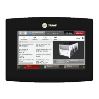
Page 19: Tracer Td7 Operator Interface
Tracer TD7 Operator Interface Information is tailored to operators, service technicians, and owners. When operating a chiller, there is specific information you need on a day-to-day basis—setpoints, limits, Sound power levels diagnostic information, and reports. Figure 3 - TD7 operator interface report... -
Page 20: Tracer™ Tu
Current amps (3) tasks. of the affected portion, Special Action means a special Start-up amps 14,1 16,5 Tracer TU serves as a common interface to all Trane® action or mode of operation (limp along) is invoked, but Air flow minimum 1400 1800... - Page 21 Notes Sound power levels Discharge Measurement conditions: Measurements taken in a room adjacent to the room containing the FWD, at the outlet of the rectangular duct (1.5 m long) fixed to its discharge opening. Power level in dB(A), per Hz frequency band Overall power Unit speed...
- Page 22 Notes Technical Data Power supply (V/Ph/Hz) 230/1/50 Capacities Cooling capacity on water (1) (kW) 18,8 30,1 Heating capacity on water (2) (kW) 11,9 18,9 20,9 38,2 Fan motor (type) 2 x direct drive centrifugal Fan power input (3) (kW) 0,23 0,46 0,65 1,04...
- Page 23 Notes Sound power levels Discharge Measurement conditions: Measurements taken in a room adjacent to the room containing the FWD, at the outlet of the rectangular duct (1.5 m long) fixed to its discharge opening. Power level in dB(A), per Hz frequency band Overall power Unit speed...
- Page 24 Trane optimizes the performance of homes and buildings around the world. A business of Ingersoll Rand, the leader in creating and sustaining safe, comfortable and energy efficient environments, Trane offers a broad portfolio of advanced controls and HVAC systems, comprehensive building services and parts. For more information visit www.Trane.com...
Need help?
Do you have a question about the Tracer TD7 and is the answer not in the manual?
Questions and answers