
Related Manuals for Trane Thermo King CANAIRE


Summary of Contents for Trane Thermo King CANAIRE
- Page 1 Operator’s Manual BUS HVAC UNIT Revision A T T K K 5 5 3 3 0 0 5 5 0 0 - - 3 3 - - O O P P - - E E N N June 2020...
- Page 2 Introduction This manual is published for informational purposes only. Thermo King® makes no representations warranties express or implied, with respect to the information recommendations and descriptions contained herein. Information provided should not be regarded as all-inclusive or covering all contingencies. If further information is required, Thermo King Corporation Service Department should be consulted.
- Page 3 I I n n t t r r o o d d u u c c t t i i o o n n • The warranty on your new unit is valid only when the repair and replacement of component parts is performed by an authorized Thermo King dealer Machine Information Policy Use of this product serves as acceptance of the Thermo King Machine...
- Page 4 I I n n t t r r o o d d u u c c t t i i o o n n • Ambient temperature • Probable Cause of Fault • Warranty Details of the Unit • Payment Details for the Repair Leave your name and contact number and a Thermo Assistance Operator will call you back.
- Page 5 I I n n t t r r o o d d u u c c t t i i o o n n Customer Satisfaction Survey Let your voice be heard! Your feedback will help improve our manuals. The survey is accessible through any internet-connected device with a web browser.
-
Page 6: Table Of Contents
Table of Contents S S a a f f e e t t y y ....................... . 8 8 Danger, Warning, Caution, and Notice . - Page 7 T T a a b b l l e e o o f f C C o o n n t t e e n n t t s s I I n n t t e e l l l l i i g g A A I I R R E E I I I I I I C C o o n n t t r r o o l l l l e e r r ..............3 3 1 1 Alarms.
-
Page 8: Danger, Warning, Caution, And Notice
Safety Danger, Warning, Caution, and Notice Thermo King® recommends that all service be performed by a Thermo King dealer and to be aware of several general safety practices. Safety advisories appear throughout this manual as required (refer to examples below). Your personal safety and the proper operation of this unit depend upon the strict observance of these precautions. -
Page 9: General Safety Practices
S S a a f f e e t t y y General Safety Practices D D A A N N G G E E R R R R i i s s k k o o f f I I n n j j u u r r y y ! ! Keep hands and loose clothing clear of fans and belts at all times when the unit is operating with the doors open. -
Page 10: Battery Removal
S S a a f f e e t t y y Battery Removal W W A A R R N N I I N N G G H H a a z z a a r r d d o o f f E E x x p p l l o o s s i i o o n n ! ! When removing battery cables, ALWAYS disconnect the negative battery terminal first. - Page 11 S S a a f f e e t t y y W W A A R R N N I I N N G G P P e e r r s s o o n n a a l l P P r r o o t t e e c c t t i i v v e e E E q q u u i i p p m m e e n n t t ( ( P P P P E E ) ) R R e e q q u u i i r r e e d d ! ! Refrigerant in a liquid state evaporates rapidly when exposed to the atmosphere, freezing anything it contacts.
-
Page 12: Refrigerant Oil
S S a a f f e e t t y y Refrigerant Oil Observe the following precautions when working with or around refrigerant oil: W W A A R R N N I I N N G G P P e e r r s s o o n n a a l l P P r r o o t t e e c c t t i i v v e e E E q q u u i i p p m m e e n n t t ( ( P P P P E E ) ) R R e e q q u u i i r r e e d d ! ! Protect your eyes from contact with refrigerant oil. - Page 13 S S a a f f e e t t y y • E E y y e e s s : : Immediately flush with large amounts of water for at least 15 minutes. Get prompt medical attention. • S S k k i i n n : : Remove contaminated clothing.
- Page 14 S S a a f f e e t t y y Move victim to fresh air and use Cardio Pulmonary Resuscitation (CPR) or mouth-to-mouth resuscitation to restore breathing, if necessary. Stay with victim until emergency personnel arrive. TK 53050-3-OP-EN...
-
Page 15: General Features
General Description General Features Thermo King’s Heating, Ventilation and Air Conditioning (HVAC) systems provide cooling, dehumidifying and heating of the air. Units contain refrigeration circuit. The refrigeration medium is charged/ transported by a compressor via installation pipes & hoses. Components are arranged for easy access and service through removable covers. - Page 16 CANAIRE Controller BEE372 ON/OFF button. Two possibilities when driver panel is powered: • Welcome screen with actual date and time and TK logo > BED865 driver panel is powered but out of operation > to start press ON/OFF button. • Standard operating screen.
-
Page 17: C C A A N N A A I I R R E E C C O O N N T T R R O O L L L L E E R
C C A A N N A A I I R R E E C C o o n n t t r r o o l l l l e e r r Preheater setting button — see ???. BED877 Operating Mode selection button —... -
Page 18: Setting Preheater Wake Up Time
C C A A N N A A I I R R E E C C o o n n t t r r o o l l l l e e r r The compressor is always controlled by HVAC unit. If the cooling function is required by Front Box only the compressor doesn't start. -
Page 19: Lcd Graphic Display
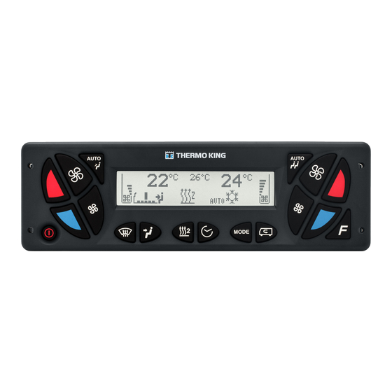
C C A A N N A A I I R R E E C C o o n n t t r r o o l l l l e e r r LCD Graphic Display Figure 1. LCD Graphic’s display BED776 11 10 Driver's area temperature set point... -
Page 20: Setup
C C A A N N A A I I R R E E C C o o n n t t r r o o l l l l e e r r Setup Press the 3 buttons AUTO Driver and AUTO Start Passenger and SMOG for 3 seconds to enter Main Menu. - Page 21 C C A A N N A A I I R R E E C C o o n n t t r r o o l l l l e e r r Language Smog timer Preheater Tiner • Time Setup Date and Time Setup Preheater Wake Up...
-
Page 22: Specifications
C C A A N N A A I I R R E E C C o o n n t t r r o o l l l l e e r r Specifications APPLICATION Control of HVAC unit SETUP TEMPERATURE RANGE 17 °C (63 °F) to 27 °C (80 °F) Display in °C and °F as firmware option... - Page 23 ClimaAIRE I D Controller auto auto auto BEE373 The Red Alarm (ALARM) symbol will shine in the following two conditions: • high or low pressure switches are OFF longer than 10 minutes • high or low pressure switches are OFF 5 times per 10 minutes In both cases, the unit will switch to the Ventilation Mode.
-
Page 24: C C L L I I M M A A A A I I R R E E I I D D C C O O N N T T R R O O L L L L E E R
C C l l i i m m a a A A I I R R E E I I D D C C o o n n t t r r o o l l l l e e r r Reheat/Auto mode. -
Page 25: Operating Instructions
C C l l i i m m a a A A I I R R E E I I D D C C o o n n t t r r o o l l l l e e r r Return air temperature icon Setpoint icon Display... -
Page 26: Specifications
C C l l i i m m a a A A I I R R E E I I D D C C o o n n t t r r o o l l l l e e r r Specifications APPLICATION Control of HVAC unit... - Page 27 ClimaAIRE II Controller auto auto auto BEE374 The Red Alarm (ALARM) symbol will shine in the following two conditions: • high or low pressure switches are OFF longer than 10 minutes • high or low pressure switches are OFF 5 times per 10 minutes In both cases, the unit will switch to the Ventilation Mode.
-
Page 28: C C L L I I M M A A A A I I R R E E I I I I C C O O N N T T R R O O L L L L E E R
C C l l i i m m a a A A I I R R E E I I I I C C o o n n t t r r o o l l l l e e r r The inside temperature in Zone 1 is displayed. -
Page 29: Operating Instructions
C C l l i i m m a a A A I I R R E E I I I I C C o o n n t t r r o o l l l l e e r r To cool the passenger compartment, turn the knob to the LEFT. -
Page 30: Specifications
C C l l i i m m a a A A I I R R E E I I I I C C o o n n t t r r o o l l l l e e r r Specifications APPLICATION Control of HVAC unit... - Page 31 IntelligAIRE III Controller Figure 2. Pressure Display Module (PDM) PRESSURE PSIG SUCT 1 DISCH 1 SUCT 2 DISCH 2 BEE375 3-Digit LED Display Discharge Pressure 1 button - compressor 1: Pressing the DISCH 1 button displays the discharge pressure for compressor 1.
-
Page 32: I I N N T T E E L L L L I I G G A A I I R R E E I I I I I I C C O O N N T T R R O O L L L L E E R
I I n n t t e e l l l l i i g g A A I I R R E E I I I I I I C C o o n n t t r r o o l l l l e e r r Figure 3. -
Page 33: Alarms
I I n n t t e e l l l l i i g g A A I I R R E E I I I I I I C C o o n n t t r r o o l l l l e e r r Alarm Indicator - Red or Yellow Ambient Light Sensor Alarms... -
Page 34: Specifications
I I n n t t e e l l l l i i g g A A I I R R E E I I I I I I C C o o n n t t r r o o l l l l e e r r Specifications APPLICATION Control of HVAC unit... - Page 35 FrontAIRE II Controller AUTO A C / BEE377 2 3 4 9 10 Press the button to turn the unit ON. Press ON /OFF Button again to turn it OFF. BEE385 The Red Alarm Symbol (LED) will be ON in the case of: •...
-
Page 36: F F R R O O N N T T A A I I R R E E I I I I C C O O N N T T R R O O L L L L E E R
F F r r o o n n t t A A I I R R E E I I I I C C o o n n t t r r o o l l l l e e r r Lower Value button: Press the button to decrease the desired setpoint. -
Page 37: Operating Instructions
F F r r o o n n t t A A I I R R E E I I I I C C o o n n t t r r o o l l l l e e r r The stepless control of the air distribution AIR DISTRIBUTION damper. -
Page 38: Preheater Time Setting
F F r r o o n n t t A A I I R R E E I I I I C C o o n n t t r r o o l l l l e e r r Real time / minutes - right blinking numbers w/o dots (set minutes). -
Page 39: Specifications
F F r r o o n n t t A A I I R R E E I I I I C C o o n n t t r r o o l l l l e e r r SPECIFICATIONS APPLICATION Control of HVAC front box unit... - Page 40 Warranty Please also refer to TK 61830-3-OP Thermo King Standard Warranty Terms & Conditions for Bus HVAC Air Conditioning Units available on https://www. emea-user-manuals.thermoking.com/global/europe.html or on request from your Thermo King Dealer. TK 53050-3-OP-EN...
-
Page 41: Pre-Trip Inspections
Maintenance Inspection Schedule A closely followed maintenance program will help to keep your Thermo King unit in top operating condition. Coordinate the maintenance inspection schedule with the Bus Preventive Maintenance Schedule. Ask your Thermo King dealer representative for the Thermo King Bus A/C Preventive Maintenance forms for more information. N N o o t t e e : : Thermo King reserves the right to deny warranty coverage on claims due to lack of maintenance or neglect. - Page 42 M M a a i i n n t t e e n n a a n n c c e e I I n n s s p p e e c c t t i i o o n n S S c c h h e e d d u u l l e e Examples are shown in the table below.
- Page 43 Recover Refrigerant N N o o t t e e : : In the USA, EPA Section 609 Certification is required to work on motor vehicle air conditioning systems (MVAC). At Thermo King®, we recognize the need to preserve the environment and limit the potential harm to the ozone layer that can result from allowing refrigerant to escape into the atmosphere.
- Page 44 Thermo King – by Trane Technologies (NYSE: TT), a global climate innovator – is a worldwide leader in sustainable transport temperature control solutions. Thermo King has been providing transport temperature control solutions for a variety of applications, including trailers, truck bodies, buses, air, shipboard containers and railway cars since 1938.
Need help?
Do you have a question about the Thermo King CANAIRE and is the answer not in the manual?
Questions and answers