Trane Tracer TD7 Manual
With uc 800
Hide thumbs
Also See for Tracer TD7:
- Installation, operation and maintenance manual (72 pages) ,
- User manual (32 pages) ,
- User manual (24 pages)

Related Manuals for Trane Tracer TD7


Summary of Contents for Trane Tracer TD7
- Page 1 Tracer™ TD7 with UC 800 January 2021 RLC-SVU007E-GB Confi dential and proprietary Trane information Original instructions...
-
Page 2: Table Of Contents
Smart Com protocol ................19 *water temperature: min. +2° C/max. 100° C *absolute service pressure: min 1 bar/max 11 bars Rotary Switches ..................19 LED Description and Operation ............. 20 Tracer TD7 Operator Interface ................. 21 Tracer™ TU ....................... 22 RLC-SVU007E-GB UNT-PRC002-GB... -
Page 3: General Recommendations
Follow proper lockout/tagout procedures to ensure the power cannot be inadvertently energized. • For variable frequency drives or others energy storing component provided by Trane or others, refer to the appropriate manufacturer’s literature for allowable waiting periods for discharge of capacitors. Verify with an FWD 20 appropriate voltmeter that all capacitors have discharged. - Page 4 General Recommendations Technical Data WARNING! Discharge Time: Frequency converters contain DC-link capacitors that can remain charged even when the frequency converter is not powered. To avoid electrical hazards, disconnect AC mains, any permanent magnet type motors, and any remote DC link power supplies, including battery backups, UPS and DC-link connections to other frequency converters.
-
Page 5: Installer-Supplied Components / Interconnecting Wiring
Installer-Supplied Components / Interconnecting Wiring Installer-Supplied Components Customer wiring interface connections are shown in the electrical schematics and connection diagrams that are shipped with the unit. The installer must provide the following components if not ordered with the unit: • Power supply wiring (in conduit) for all field-wired connections. Sound power levels •... -
Page 6: Fan Power Input (3) (Kw)
Installer-Supplied Components / Interconnecting Wiring Technical Data Power supply (V/Ph/Hz) 230/1/50 Capacities Cooling capacity on water (1) (kW) 18,8 30,1 Heating capacity on water (2) (kW) 11,9 18,9 20,9 38,2 Fan motor (type) 2 x direct drive centrifugal Fan power input (3) (kW) 0,23 0,46... -
Page 7: Programmable Relays
Programmable Relays A programmable relay concept provides for enunciation of certain events or states of the chiller, selected from a list of likely needs, while only using four physical output relays, as shown in the field wiring diagram. The four relays are provided (generally with a Quad Relay Output LLID) as part of the Programmable Relay Option. The relays contacts are isolated Form C (SPDT), suitable for use with 120 VAC circuits drawing up to 2.8 amps inductive, 7.2 amps resistive, or 1/3 HP and for 240 VAC circuits drawing up to 0.5 amp resistive. -
Page 8: Air Flow Relay Assignments Using
Relay Assignments Using Technical Data Tracer™ TU Tracer™ TU Service Tool is used to install the Programmable Relay Option package and assign any of the above lists of events or status to each of the four relays provided with the option. (See “Tracer™ TU, ” for more information on the Tracer TU service tool) The relays to be programmed are referred to by the relay’s terminal numbers on the LLID board 1A10. -
Page 9: Low Voltage Wiring / Ice Making (Optional)
Low Voltage Wiring / Ice Making (Optional) Low Voltage Wiring The remote devices described below require low voltage wiring. All wiring to and from these remote input devices to the Control Panel must be made with shielded, twisted pair conductors. Be sure to ground the shielding only at the panel. - Page 10 Ice Making (Optional) Technical Data Ice Making Command This is the command to enter ice making. This setting is defined as an Auto/On settings. Setting this to On will command the application into ice building if ice building is enabled and the Chiller is in the “Auto” command mode. Setting the Ice Making command to Auto will command the application to follow the next priority functional mode.
-
Page 11: External Setpoints & Capacity Outputs (Optional)
External setpoints & capacity outputs (Optional) External Chilled Water Setpoint (ECWS) The UC800 provides inputs that accept either 4-20 mA or 2-10 VDC signals to set the external chilled water setpoint (ECWS). This is not a reset function. The input defines the setpoint. This input is primarily used with generic BAS (building automation systems). -
Page 12: External Current Limit Setpoint (Ecls)
Like previously, either 2-10 VDC (default) or 4-20 mA inputs are available as option to set External Current Limit Setpoint. The Demand Limit Setting can also be set via the Tracer TD7 or through digital communication with Tracer (Comm4). The arbitration of the various sources of demand limit is described in the flow charts at the end of this section. -
Page 13: Ecws And Ecls Analog Input Signal Wiring Details
External setpoints & capacity outputs (Optional) ECWS and ECLS Analog Input Signal Wiring Details Both the ECWS and ECLS can be connected and setup as either a 2-10 VDC (factory default), 4-20 mA, or resistance input (also a form of 4-2OmA) as indicated below. Tracer TU must be used to set Analog Input Signal LLID type. This is done by a setting change on the Custom Tab of the Configuration View within Tracer TU. -
Page 14: Chilled Water Reset (Cwr)
Chilled Water Reset (CWR) Technical Data Functional Description The UC800 shall reset the chilled water temperature setpoint based on return water temperature or outdoor air temperature. The Return Reset and Outdoor Reset functions are standard. The chilled water reset settings are as follows: 1. - Page 15 Chilled Water Reset (CWR) Using the Equations for calculating CWR Notes for doing calculations: Equation used to get Degrees of Reset: Outdoor Air: Sound power levels Degrees of Reset = Reset Ratio * (Start Reset - TOD) Return Reset: Discharge Degrees of Reset = Reset Ratio * (Start Reset - (TWE - TWL)) Measurement conditions: Const Return:...
- Page 16 Chilled Water Reset (CWR) Technical Data Reset Ratio = -70% Start Reset =32.22 °C =37.77°C Maximum Reset =9.44 °C Power supply (V/Ph/Hz) 230/1/50 Capacities Cooling capacity on water (1) (kW) 18,8 30,1 How many Degrees of Reset will there be? Heating capacity on water (2) (kW) 11,9...
- Page 17 Chilled Water Reset (CWR) How many Degrees of Reset will there be? Degrees of Reset = Reset Ratio*(Start Reset - (TWE-TWL)) Degrees of Reset = .5*(-6.67-(18.3-7.22)) Degrees of Reset = -8.875 Sound power levels Discharge Reset Ratio = 70% Measurement conditions: Start Reset = -6.67°C Measurements taken in a room adjacent to the room containing the FWD, at the outlet of the rectangular duct (1.5 m...
-
Page 18: Smart Communication Protocol
Smart Communication Protocol Technical Data LonTalk™ Interface (LCI-C) UC800 provides an optional LonTalk™ Smart Com Protocol (LCI-C) between the chiller and a Building Automation System (BAS). An LCI-C LLID shall be used to provide “gateway” functionality between a LonTalk compatible device and the Chiller. -
Page 19: Wiring And Port Descriptions For Modbus, Bacnet And Lontalk
Wiring and Port Descriptions for MODBUS, BACnet and LonTalk Figure 1 illustrates the UC800 controller ports, LEDs, rotary switches, and wiring terminals. The numbered list following Figure 1 Wiring locations and connection ports corresponds to the numbered callouts in the illustration. Figure 1 –... -
Page 20: Led Description And Operation
Wiring and Port Descriptions for MODBUS, BACnet and LonTalk Technical Data LED Description and Operation There are 10 LEDs on the front of the UC800. Figure 2 shows the locations of each LED and Table 5 describes their behavior in specific instances. Figure 2 –... -
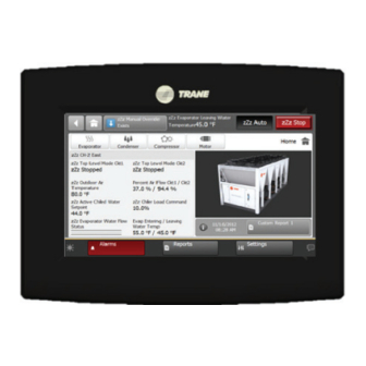
Page 21: Tracer Td7 Operator Interface
Tracer TD7 Operator Interface Information is tailored to operators, service technicians, and owners. When operating a chiller, there is specific information you need on a day-to-day basis—setpoints, limits, diagnostic information, and reports. Figure 3 – TD7 operator interface report Sound power levels... -
Page 22: Tracer™ Tu
This portable PC-based service-tool software supports service and maintenance tasks, and is required for software upgrades, configuration changes and major service tasks. Tracer TU serves as a common interface to all Trane® chillers, and will customize itself based on the properties of the Power supply... - Page 23 Tracer™ TU Criteria: Quantitatively defines the criteria used in generating the diagnostic and, if nonlatching, the criteria for auto reset. If more explanation is necessary a hot link to the Functional Specification is used. Reset Level: Defines the lowest level of manual diagnostic reset command which can clear the diagnostic. The manual diagnostic reset levels in order of priority are: Local or Remote.
- Page 24 For more information, please visit trane.com or tranetechnologies.com. Trane has a policy of continuous product and product data improvement and reserves the right to change design and specifications without notice. We are committed to using environmentally conscious print practices.
Need help?
Do you have a question about the Tracer TD7 and is the answer not in the manual?
Questions and answers