Advertisement
Table of Contents
- 1 Warnings, Cautions, and Notices
- 2 Packaged Contents
- 3 Required Tools
- 4 Mounting and Removing the Tracer SC and the Power Supply Module
- 5 Removing or Repositioning the Tracer SC or the Power Supply Module
- 6 Wiring and Applying Power
- 7 Specifications
- 8 Agency Listings and Compliance
- Download this manual
Installation Instructions
®
Tracer
SC System Controller
with PM014 Supply Module
Order Number: BMSC000AAA01100
SAFETY WARNING
Only qualified personnel should install and service the equipment. The installation,
starting up, and servicing of heating, ventilating, and air-conditioning equipment
can be hazardous and requires specific knowledge and training. Improperly
installed, adjusted or altered equipment by an unqualified person could result in
death or serious injury. When working on the equipment, observe all precautions in
the literature and on the tags, stickers, and labels that are attached to the
equipment.
December 2020
BAS-SVN215J-EN
2
Hazardous Voltage!
Disconnect all electrical power, including remote disconnects, before
servicing. Follow proper lockout/tagout procedures to ensure the power
cannot be inadvertently energized. Failure to disconnect power before
service could result in death or serious injury.
Mounting and Removing the Tracer SC and the
Power Supply Module
• The mounting location must meet the temperature and humidity
Specifications as outlined in
• Do not mount on a flat surface, such as on a floor or on top of a table.
Mount in an upright position with the front facing outward.
To mount the Tracer SC or the power supply module:
1. Hook the top half of the Tracer SC onto the DIN rail.
2. Gently push on the lower half of the Tracer SC until the release clip
snaps into place.
3. Hook the top half of the power supply module onto the DIN rail next
to the Tracer SC.
4. Gently push lower half of power supply module until the release clip
snaps into place.
Mounting the Tracer SC
(or the power supply
module)
X3641154-01
© 2020 Trane
WARNING
Table
1.
snap
1
Warnings, Cautions, and Notices
Read this manual thoroughly before operating or servicing this unit.
Safety advisories appear throughout this manual as required. Your
personal safety and the proper operation of this machine depend upon
the strict observance of these precautions.
The three types of advisories are defined as follows:
Indicates a potentially hazardous situation
WARNING
which, if not avoided, could result in death or
serious injury.
Indicates a potentially hazardous situation
CAUTION
which, if not avoided, could result in minor or
moderate injury. It could also be used to alert
Indicates a situation that could result in
NOTICE
equipment or property-damage only accidents.
Packaged Contents
One (1) Tracer SC module
(controller)
Two (2) 4-position terminal block
plugs
One (1) LON termination kit
One (1) Installation sheet
One (1) phone cable
Required Tools
• 5/16 in. (8 mm) slotted screwdriver
• 1/8 in. (3 mm) slotted screwdriver
3
Removing or Repositioning the Tracer SC or the
Power Supply Module
To remove or reposition the Tracer SC or the power supply module:
1. Insert a screwdriver into the slotted release clip and gently pry
upward on the clip with the screwdriver, OR;
If the screwdriver fits the slot size, insert the screwdriver into the
slotted release clip and rotate it to the left or right to release tension
on the clip.
2. While holding tension on the slotted release clip, lift the Tracer SC (or
power supply module) upward to remove or reposition.
3. If repositioning, push on the Tracer SC (or power supply module) until
the slotted release clip snaps back into place.
Removin
g the
Tracer SC
One (1) Power supply module (PM014)
Six (6) 3 position terminal block plugs
Two (2) 2 position terminal block plugs
One (1) IMC power cable 3 in. (75 mm)
long
Advertisement
Table of Contents

Subscribe to Our Youtube Channel
Related Manuals for Trane Tracer SC


Summary of Contents for Trane Tracer SC
- Page 1 Removin 1. Hook the top half of the Tracer SC onto the DIN rail. g the 2. Gently push on the lower half of the Tracer SC until the release clip Tracer SC snaps into place. 3. Hook the top half of the power supply module onto the DIN rail next to the Tracer SC.
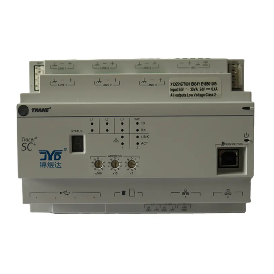
- Page 2 Tracer SC front panel 1. Connect one end of the provided IMC power cable to the IMC connection on the Tracer SC. Connect the other end of the IMC power cable to the IMC connection on the power supply module.
Need help?
Do you have a question about the Tracer SC and is the answer not in the manual?
Questions and answers