
Related Manuals for Univox PLS-X Series


Summary of Contents for Univox PLS-X Series
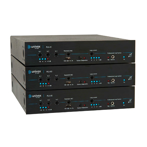
- Page 1 Univox® PLS-X1-5 Induction Loop Drivers Installation Guide Univox® PLS-X1 Part No 217100 Univox® PLS-X3 Part No 217300 Univox® PLS-X5 Part No 217500...
-
Page 2: Table Of Contents
Content Introduction ........................4 Package contents ......................4 Connections and controls ..................... 5 1. Input level control ..................... 6 2. Input level LEDs ....................6 3-4. Parametric MLC ....................6 5. System Diagnostics .................... 6 6. Loop Current Control ..................7 7. - Page 3 Technical Specification ....................13 Audio Input 1 ......................13 Audio Input 2 ......................13 Input 3 ........................14 Out Pre Amp ......................14 In Pow Amp ......................14 Supplementary Outputs ..................15 Loop Output ......................15 Default Settings ......................16 Rear panel .......................16 Front panel ......................16 Installation ........................16 Commissioning ......................18 General Notes ......................18 Trouble shooting......................19 Safety ..........................21...
-
Page 4: Introduction
Introduction Thank you for choosing Univox. The new Univox PLS-X series loop drivers combine nearly 50 years of ® experience with the latest in electronic design to deliver unrivaled sound clarity, power and performance in a compact stylish housing. Our Engineering Simplicity philosophy is evident in the functionality and ease of use of each model. -
Page 5: Connections And Controls
8. 9. Input 3 Input 2 Input 1 Out Pre PUSH In Pow www.univox.eu Monitor 1. Input Level Control 16. Remote Output Monitor Connector 2. Input Level LEDs 17. Monitor Volume Control 3. Parametric MLC Control 18. Input Power Amplifier (In Pow Amp) 4. -
Page 6: Input Level Control
If signal limiting occurs, the red Clip LED (8.) will illuminate. 5. System Diagnostics Univox PLS-X series has a built-in system test. We recommend that this feature is used periodically, at least monthly, to check the integrity of the loop driver, its inputs and the loop condition. -
Page 7: Loop Current Control
However, the only way to set the output level to the correct IEC level is to use a professional field strength meter, preferably Univox FSM 2.0. 8. Voltage Clipping/Peak LED The voltage clipping/peak LED will illuminate when the voltage is clipped, i.e. -
Page 8: Loop Monitor/Headphones Socket
In some cases metal reinforcement can actually reduce the voltage requirement. 9. Loop Monitor/Headphones Socket Univox PLS-X series has a powerful 10 W speaker amplifier and a 3.5 mm ® headphone socket built-in. The headphone socket is on the front panel, the speaker connectors and volume control are on the rear. -
Page 9: Dc Supply Socket
DC supply socket on the rear panel. The voltage rating of the supply is dependent on the model. Only Univox approved power supplies correctly rated for the Loop driver model should be used. The use of incorrectly rated, or third party power supplies will invalidate your 5 year warranty. -
Page 10: Monitor Volume Control
This output provides a feed for an additional loop driver. It should be connected to the additional loop driver at a point that is after the pre-amplification and AGC. For the PLS-X series this is input (17.) In Pow Amp. Fig 2. Daisy chaining PLS-X Series Loop Drivers 17. -
Page 11: Input 3
20. Input 3 Input 3 Input 3 is an unbalanced line input. The sensitivity is adjusted using the control on the front panel. The source may be connected using the RCA connector or the Phoenix screw terminal. 21. Input 2 Input 2 Input 2 is a switchable Line/50-100 V line input. -
Page 12: Override On/Off Dil Switch
24. Override On/Off DIL Switch Input 1 PUSH With the DIL switch in the ‘down’ position, Input 3 is set as the Priority Input. In this case, when a signal is detected, all other inputs will be suppressed. This functionality is ideal when connecting to an alarm system such as a voice alarm. -
Page 13: Technical Specification
With the DIL switch in the ‘down’ position phantom power is turned ON. With the DIL switch in the ‘up’ position, phantom power is turned OFF. The phantom power or bias voltage is approximately 12V (some variation occurs, depending on the loop driver model). Note 1 Phantom Power should only be turned on when an electret microphone is connected. -
Page 14: Input 3
Line (DIL switches 2 and 3 up) Balanced line sensitivity 140 mV-8.3 V (-15 dBu to 20.6 dBu) Override: Suppresses Inputs 1 and 2 and gives priority to Input 3 for use with voice alarms or other audio DIL switch 4 ‘down’ = ON DIL switch 4 ‘up’... -
Page 15: Supplementary Outputs
Supplementary Outputs Connection Type: Phoenix screw terminal (6 connections) Connection Type Function Specification Audio Monitor speaker 10 W IC power chip, 4-32 Ω output Ground Ground Ground DC power Auxiliary power 19-36 V, 100 mA DC supply supply LED driver Indicates output Suitable for direct connection of current = 0dB LED or external diagnostic test... -
Page 16: Default Settings
System Diagnostic = Off (switch in left position). Parametric MLC = 2 kHz (switch in right position). Installation 1. Place the loop driver in a suitable location. There are three placement options for the PLS-X series drivers: • In a 19" rack •... - Page 17 Note The PLS-X series is convection cooled for silent operation, improved reliability and longer operational life. The case forms part of the cooling system. The unit is very efficient and at minimum 0.3 Ω (PLS-X1), 0.4 Ω (PLS-X3) and 0.5 Ω (PLS-X5) loop resistance, no ventilation space in the rack is required.
-
Page 18: Commissioning
Commissioning The process for commissioning a loop system to the IEC performance standard, IEC 60118-4, can be found in the user guide for the Univox FSM 2.0 field strength meter, on the Univox Certificate of Conformity or in the equipment ®... -
Page 19: Trouble Shooting
Trouble shooting Symptom Possible cause Solution Power LED is off Power supply not Connect power supply correctly connected Power supply faulty Replace power supply Power LED is on, Loop is not correctly Check that loop wire is correctly Clip/Peak LED is connected connected to loop terminal on (brightly red) - Page 20 Intelligibility Low frequency masking Turn speech enhancement filter of sound from microphone is Poor microphone user Train user poor techniques Microphone Phantom power not turned Turn phantom power on connected, input LEDs are off Input level too low Increase input level/reduce speaking distance Use valid microphone or connect Microphone needs higher...
-
Page 21: Safety
Furthermore:- Only use the power adapter supplied with the unit. If the power adapter or cable is damaged do not use and replace with a genuine Univox part. Only operate the unit in a well ventilated, dry environment. Do not cover the power adapter or loop driver. Doing so may cause a fire. -
Page 22: Environment
To prevent possible harm to the environment and human health, at the end of serviceable life of the product, please dispose of responsibly by following statutory Disposal Regulations. Measuring devices Univox® FSM 2.0, Field Strength Meter Instrument for the professional measurement and certification of loop systems in accordance with IEC 60118-4. - Page 24 Distributor Univox by edin, the world's leading authority and producer of high quality hearing loop systems created the first true loop amplifier in 1969. With our strong emphasis on research and development, we have continued to innovate to deliver more firsts in the industry, constantly improving the performance of our products and service for hard of hearing communities worldwide.
Need help?
Do you have a question about the PLS-X Series and is the answer not in the manual?
Questions and answers