Table of Contents
Advertisement
Advertisement
Table of Contents

Subscribe to Our Youtube Channel
Related Manuals for Flightline SPITFIRE MK.IXC


Summary of Contents for Flightline SPITFIRE MK.IXC
-
Page 2: Table Of Contents
Catalog I nt r od u c ti o n ······························ .. ·················································································································1 Ba s i c I n fo r ma ti o n ............................2 P a c ka g e L i s t ······ ............................2 Assembly Instructions Fuselage Assembly·······················... -
Page 3: I Nt R Od U C Ti O
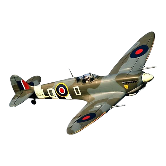
BOA ESC. With the recommended 6S 4000-S00OmAh lipo battery, the Spitfire MK.IXc has a level top speed of 125kph/75mph, with tall vertical power and 4-8 minutes of flight time depending on throttle management. To enhance grass performance, the main landing gear uses shock absorbing Oleo struts, a main wheel diameter of 85mm, and a tail wheel diameter of 45mm. -
Page 4: Ba S I C I N Fo R Ma Ti O N
Product basic information Wing loading: 74g/dm Wing area : 46.5dm Motor: 5055-390KV ..brush less outrunner motor Propeller : 4-Blade 16x 10 ESC: 80A (1 pc) Servo: : 17g MGx6pcs Weight: 2850g (W/O battery) ..Flight speed: 125KMH Aileron: Yes Elevator: Yes Steering pushrod: Yes Flap: Yes... -
Page 5: Fuselage Assembly
PNP Assembly Instructions 1. Before assembly, remove the battery compartment and the fuselage pushrods in the plastic Fuselage Assembly tube. Install the ball-head buckle on the pushrods. Then insert the rudder push rod from tail fuselage section into the front fuselage plastic tube. 2. -
Page 6: Aileron Push Rod Installation
PNP Assembly Instructions 1. Insert one side of rudder pushrod A ,through plastic tube B, to the servo arm C. 2.Buckle the ball head buckle of rudder push rod to the rudder horn D . & Note: When installing the rudder pushrod, make sure the tail wheel is centered. -
Page 7: Pushrod Instructions
PNP Assembly Instructions Step(;) � tic pieceA 5. Pull the main wing servo cables from the fuselage up into the battery �-�"- compartment. 6. Insert the main wing plastic joiner pieces, A and B to the underside of the wing, as shown. Finally, use the four machine screws to attach the wing to the fuselage. -
Page 8: Scale Parts Installation
PNP Assembly Instructions Scale parts Installation 2.Use 1xPWM4x8mm screw to attach the air intake. 1.Glue the Radiators A and B to the main wing surfaces, as shown. Screw -------- (PWM4 x8 mm) Stepf) 4.Use clear canopy glue to attach the scale rearview mirror to the clear canopy. -
Page 9: Battery Installation
PNP Assembly Instructions Battery Installation To remove the battery Place the battery into the front of the hatch, lift up on the tape. fuselage using the provided rubber matting or Velcro to secure it. Battery cabin size: L=260 W=76 H=45(mm) Before connecting the battery to the ESC, please The battery capacity and discharge rate we remove the propeller. -
Page 10: Control Direction Test
PNP Assembly Instructions Control direction test After installed the plane, before flying, we need a fully charged battery and connect to the ESC, then use radio to test and check that every control surface work properly. Ailerons • • Stick Left Stick Right !!!!!!!! !!!!!!!! -
Page 11: Dual Rates And Preflight Considerations
PNP Assembly Instructions l•fftifiiiii According to our test results, the following rates proved to be a good starting point. Low rates are good for initial flights or for less experienced pilots. Adjust rates to suit your own style. Aileron(ls Side) Elevator (Is Side) Rudder (The Bottom) Flaps H1/H2 31 mm/31 mm... -
Page 12: Accessories Description
Accessories Description "' " , . · · · Servos Introductions · � " '" ,. 0 · A servo or reversed servo is defined as follows: When the servo input signal changes from 1000ųs to 2000ųs, if the servo arm rotates clockwise, it's a positive servo. -
Page 13: Power System Installation
Accessories Description Power system installation ------------------------------------------ /�- A-Screw (KM4x8mm 4pcs) B-'Motor mount C-5O55-390KV out-runner motor D-Propeller hub E-Screw (HM2.5x1Omm 4pcs) ,.---------------------------------------------------------,. ----- ---------------------------------------------- A-Fire wall B-Screw (PA4x15mm 4pcs) C-Screw (PM3x16mm 8pcs) D-Scale propeller (16x1 4-blade) E-Scale propeller back plate As an upgrade for propeller NOTE: A-Spinner center plug strength, a metal reinforcement... -
Page 14: Main Landing Gear Installation
Accessories Description Main landing gear installation Assemble and disassemble the main landing gear according to the following photos. A-Main gear axle -C-Buckle (01.5mm) W-Screw (PA 1.4x12 2pcs) 8-Main wheel (0 85x26mm) X-Main landing gear door C-Buckle (01.5mm) C-Grub Screw (M4x4) N- C-Buckle (01.5mm) Y-Screw... - Page 15 Dongguan Freewing Electronic Technology Ltd HK Freewing Model International Limited Add.:FeiYi Building.face to Labor Bureau, Fu min Middle Road, Dalang Town, Dongguan City , Guangdong Province, China Web: http://www.sz-freewing.com Email:freewing@sz-freewing.com Tel: 86-769-82669669 Fax:86-769-82033233 *�"$"tJt�-=ff4!1��&0§J JI*�� � � "t 00 �ffi � �& 0 §J I'�...
Need help?
Do you have a question about the SPITFIRE MK.IXC and is the answer not in the manual?
Questions and answers