Advertisement
Quick Links
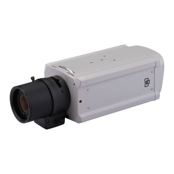
UltraView UVC-6130-1 WDR Camera Quick
Start Guide
Introduction
This is the Quick Installation Guide for the UVC-6130-1-XX WDR color
box camera.
Refer to the user manual for complete instructions on installing and
configuring this camera.
User guidelines
•
Program the camera settings as much as possible before
mounting the camera. Take appropriate safety precautions while
completing programming after installation.
•
Always use a 12 VDC or 24 VAC UL listed Class 2 power supply
to power the camera.
•
Do not use the camera over the temperature range specifications:
-10°C to +50°C (14°F to 122°F)
•
If the light source where the camera is installed experiences
rapid, wide- variations in lighting, the camera may not operate as
intended.
WARNING: To reduce the risk of fire or electronic shock, do not
expose the camera to rain or open the back of the camera.
Description
Figure 1: Camera UVC-6130-1-P/N description
1.
Video output
2.
Audio output
3.
OSD control pad
Figure 2: Camera UVC-6130-1-P2 description
1.
Video output
2.
Audio output
3.
OSD control pad
© 2012 UTC Fire & Security. All rights reserved.
4.
D/N trigger pin
5.
12 VDC / 24 VAC dual power
4.
D/N trigger pin
5.
AC96V/AC240 universal
power
Installation
Please check the package contents and make sure that the device in
the package is in good condition and all the assembly parts are
included.
Note: Before installing, please ensure that the mounting surface is
strong enough to withstand three times the weight of the camera. If the
wall is not strong enough, the camera may fall and cause serious
damage.
Install the camera
1.
Connect the video cable.
Connect a coaxial cable from the camera's BNC connector to a
CCTV monitor or video recording device.
2.
Attach the lens.
Note: For optimal performance, use an auto iris lens. Refer to the
instructions that came with the lens you purchased for complete
installation instructions of that lens.
Figure 3: Attaching the lens
1.
Camera
2.
Autoiris lens plug
3.
Lens (autoiris shown)
Screw the lens clockwise onto the lens mount of the camera. For
optimal performance, please use an auto iris lens. Plug the auto-
iris drive cable to the 4-pin interface on the side of the camera.
Note: Please prevent dust from entering between the lens mount
and the lens.
3.
Connect the power cable.
For UVC-6130-1-P/N:
With a screwdriver, loosen the ~AC24V/DC12V and GND terminal
screws on the terminal block. Connect a universal 12 VDC/24
VAC power supply to the terminal block.
Note: The terminal block is not polarity sensitive. Either power
lead can be connected to either terminal connector. There is no
need for an isolated ground wire. The two power terminals can
accept any polarity and any combination of power that equals 12
VDC or 24 VDC.
1 / 2
P/N 1072548C-EN • REV 1.0 • ISS 27JUL12
4.
DC type autoiris lens leads
A. Damping coil (+); B.
Damping coil (-); C Driving
coil (+); D Driving coil (-)
Advertisement

Related Manuals for Interlogix UltraView UVC-6130-1-N


Summary of Contents for Interlogix UltraView UVC-6130-1-N
- Page 1 UltraView UVC-6130-1 WDR Camera Quick Start Guide Introduction Installation This is the Quick Installation Guide for the UVC-6130-1-XX WDR color Please check the package contents and make sure that the device in box camera. the package is in good condition and all the assembly parts are included.
-
Page 2: Specifications
Retighten the terminal screws until snug, ensuring that the power Menu item Description leads are secure. Supply power to the unit by plugging the power Motion Det Defines the motion detection set up. supply into a proper source. Sync Displays the current synchronization mode. Note: The power LED illuminates to show that the camera is receiving power.
Need help?
Do you have a question about the UltraView UVC-6130-1-N and is the answer not in the manual?
Questions and answers