Interlogix UVD-XP4DNR(-P) User Manual
Hide thumbs
Also See for UVD-XP4DNR(-P):
- Quick start manual (9 pages) ,
- User manual (8 pages) ,
- Quick start manual (65 pages)
Table of Contents
Advertisement
Quick Links
Advertisement
Table of Contents

Related Manuals for Interlogix UVD-XP4DNR(-P)


Summary of Contents for Interlogix UVD-XP4DNR(-P)
- Page 1 UVD-XP4DNR(-P) Camera User Manual P/N 1079204B-EN • REV 1.0 • ISS 15JUN12...
- Page 2 Copyright © 2012 UTC Fire & Security. All rights reserved. Trademarks and patents Interlogix, UltraView brand and logo are trademarks of UTC Fire & Security. Manufacturer UTC Fire & Security Americas Corporation, Inc. 1275 Red Fox Rd., Arden Hills, MN 55112 6943, USA Authorized EU manufacturing representative: UTC Fire &...
-
Page 3: Table Of Contents
Content Preface 3 Safety terms 3 Product description 4 Features 4 User guidelines 4 Components 5 OSD control pad 6 Installation 6 Cable connection 6 Camera installation 7 Angle adjustment 7 Focus adjustment 7 Connect the monitor 8 Programming 9 Main menu 9 Presets menu 10 Setup menu 10... -
Page 5: Preface
Preface This is the UVD-XP4DNR(-P) Camera. This document includes an overview of the product and detailed instructions explaining: • how to connect the camera; and • how to program the camera. • how to adjust the camera angle and focus To use this document effectively, you should have the following minimum qualifications: •... -
Page 6: Product Description
Product description The UVD-XP4DNR(-P) (rugged dome) color video cameras is a 24 VAC/12 VDC model. The cameras are equipped with a digital signal processor (DSP) for processing the video signal. Features Camera features include: • Next-generation XPosure technology. • Improved low-light performance and color balance. •... -
Page 7: Components
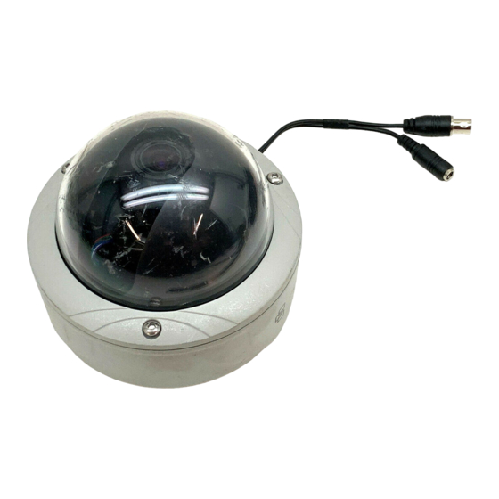
Components Figure 1 shows the main components of the rugged dome unit. Figure 1: Rugged dom2e unit Lens body Bubble Camera body OSD control pad Video monitor output Figure 3 shows the monitor output components. Figure 2: Monitor output cable A. -
Page 8: Osd Control Pad
OSD control pad The on-screen display (OSD) control pad (Figure 4) is a five-direction joystick that provides the ability to manually control the camera functions. Table 1 below lists the OSD control pad functions and describes their use. Figure 3: OSD control pad OSD control pad Table 1: OSD control pad controls Pad directions... -
Page 9: Camera Installation
Black cable. Video ground. Note: For AC24V or DC12V, Black or Red may be used for ground. Camera installation To mount the camera, attach the camera to the mounting surface using the appropriate fasteners. Angle adjustment To adjust the horizontal angle of the platform up to 180 degrees, turn the platform (Figure 4 below). -
Page 10: Connect The Monitor
Figure 5: Zoom and focus adjustment Zoom ring thumbscrew for VA2 and focus ring for Focus ring thumbscrew for VA2 and zooming ring VA9 lens for VA9 lens Connect the monitor Program the cameras by attaching a standard video monitor to the system. To connect the monitor, do the following: 1. -
Page 11: Programming
Programming This chapter describes how to navigate the setup menus to adjust the camera settings. Main menu The camera is configured through the setup menus that appear on-screen (see There is a menu map on the back page of the manual that shows the overview of the menu structure (see “Menu Map”... -
Page 12: Presets Menu
When in a submenu, you can easily move back to a previous menu, save changes as well as cancel changes and return to live mode. Select one of these options: Prev. Returns to the previous menu. Save Saves changes. Cancel Cancels and returns to live mode. - Page 13 Table 4: Setup menu options Menu option Description ID setup Configures camera identification and position. See “Camera ID setup” below for setup information. Sync Select one of the two options: INT - Internal Synch. This is used with DC Power Input as a way to reduce the phase roll of fluorescent lights.
-
Page 14: Motion Detection
Motion detection A motion detection alarm refers to an alarm triggered when the camera detects a motion. From the Setup menu, use the arrow buttons to select Motion detection and press the Enter button. The Motion Detection menu screen appears. Figure 9: Motion detection menu Table 6 below lists the Motion Detection Setup menu options. -
Page 15: Viewing Menu
Viewing menu From the Main menu, use the arrow buttons to select Viewing and press the Enter button. The Viewing menu screen appears. Figure 10: Viewing menu Table 7 below lists the Viewing menu options. Table 7: Viewing menu options Menu option Description Flip... -
Page 16: White Balance Menu
Table 8: Exposure menu options Menu option Description Configures automatic gain control (AGM). The image quality is automatically adjusted in low light conditions. Select one of the options: Medium, High, Custom, or Low. AE preferences When enabled, it automatically optimizes the image for highlights or shadows. -
Page 17: Save/Restore Menu
Menu option Description PTL – Saves the AWB (Automatic white balance) value and all changes made. Use this option with care. Save/restore menu From the Main menu, use the arrow buttons to select Save/restore and press the Enter button. Figure 13: Save/restore menu Table 10 below lists the Save/restore menu options. - Page 18 UVD-XP4DNR(-P) Camera User Manual...
-
Page 20: Menu Map
Menu Map...
Need help?
Do you have a question about the UVD-XP4DNR(-P) and is the answer not in the manual?
Questions and answers