Advertisement
Quick Links
M266F
1. Safety information
DIGITAL CLAMP MULTIMETER
The meter is completely portable, LCD, 3 1/2 digit clamp
meter with insulation test function (with option 500V
OPERATOR'S INSTRUCTION MANUAL
insulation tester unit). It has been designed according
to IEC1010-1 IEC1010-2-032 concerning electronic
measuring instruments with an overvoltage category
(CAT II 1000V & CAT III 600V) and pollution 2 and safety
requirements for hand-held current clamps for electrical
measurement and test.
Follow all safety and operating instructions to ensure
that the meter is used safely and is kept in good
operating condition.
1.1 Preliminary
When using this meter, the user must observe all normal
safety rules concerning:
HOLD
MAX 1000A~
Protection against the dangers of electronic current.
CAT ll 1000V
CAT lll 600V
266F CLAMP METER
Protection of the meter against misuse.
WITH 261 OPTION(500V)
INSULATION TESTER
A~
OFF 2000M
Full compliance with safety standards can be
1000
EXTERNAL
UNIT
200
20M
Ω
guaranteed only if used with test leads supplied. If
Hz
2k
2M
necessary, they must be replaced with the same model
200
200
or same electronic ratings. Measuring leads must be in
V~
20
750
good condition.
2k
1000
1.2 During Use
200
200
20
Never exceed the protection limit values indicated in
2
V
V~
Ω
specifications for each range of measurement.
BAT
When the meter is linked to measurement circuit, do not
touch unused terminals.
When the value scale to be measured is unknown
CAT ll 6100V
beforehand, set the range selector at the highest position.
VΩ
COM
EXT
Before rotating the range selector to change function,
CAT ll
750V~
1000V
MAX
disconnect test leads from the circuit under test.
When carrying out measurements on TV or switching
power circuits always remember that there may be high
amplitude voltage pulses at test points, which can
damage the meter. Never perform resistance
measurements on live circuits.
Always is careful when working with voltage above 60V
dc or 30V ac rms. Keep fingers behind the probe barriers
while measuring.
1.3 Symbols
Important safety information, refer to the
operating manual.
Dangerous voltage may be present.
Double insulation ( Protection class II ).
Application around and removal from
HAZARDOUS LIVE conductors is permitted.
Earth ground.
1.4 Maintenance
Before opening the meter, always disconnect test leads
from all sources of electric current.
If any faults or abnormalities are observed, the meter
can not be used any more and it has to be checked out.
Never use the meter unless the back cover and the
battery cover are in place and fastened fully.
Do not use abrasives or solvents on the meter, use a
damp cloth and mild detergent only.
01
02
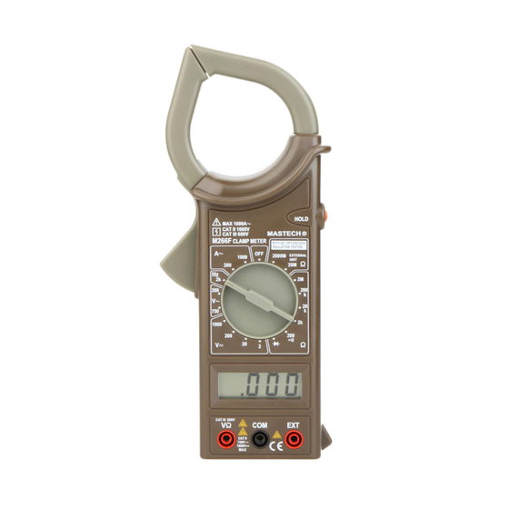
2. Description
FRONT PANEL
This meter is one of a series portable 3 1/2 digital clamp
meter for measuring DC and AC Voltage, AC current,
resistance, continuity test and insulation test. Some models
also provide frequency or temperature test. Full overload
protection. Low battery indication and over-range indication
are providing. Following table shows function of the series
of clamp meter.
FUNCTION
M266
M266F M266C
※
※
※
ACV DCV
※
※
※
ACA
※
※
※
Ω
※
※
※
※
※
※
※
INSULATION
※
TEMPERATURE
※
FREQUENCY
1. TRANSFORMER
JAWS
2. BARRIER OR
TACTILE INDICATOR
3. DATA HOLD SWITCH
4. TEMPERATURE
MEASURING SOCKET
03
2.1 Function and Range selector
A rotary switch is used to measurement functions and
ranges. When the switch is set to OFF position, the
meter does not operate.
2.2 Transformer Jaws
Pick up the AC current flowing through the conductor.
Press the TRIGGER to open the transformer jaws.
When the finger press on the TRIGGER is released, the
jaws will close again.
HOLD
MAX 1000A~
CAT ll 1000V
2.3 Data Hold
CAT lll 600V
266F CLAMP METER
WITH 261 OPTION(500V)
INSULATION TESTER
A~
Depress HOLD Button Switch to toggle in and out of the
OFF
2000M
1000
EXTERNAL
UNIT
200
20M
Ω
Hz
Data Hold mode. Releasing Data Hold mode again press
2k
2M
the button.
200
200
V~
20
750
2.4 Input Jacks
2k
1000
200
200
This meter has three input jacks that are protected
20
2
V
V~
Ω
against overload to the limits shown.
BAT
During use connect the black test lead to COM jack and
connect red test lead to V
Ω
jack. The red test lead is
depended on function selected.
CAT ll 6100V
VΩ
COM
EXT
The EXT jack is used for accept insulation tester unit
CAT ll
750V~
1000V
MAX
EXT banana Plugs, when measurement insulation
resistance.
5. ROTARY SWITCH
3. Operating Instruction
6. LCD DISPLAY
3.1 Measuring Current
7. DROP-PROOF
1. Set the rotary switch at desired A~ range position.
WRIST STRAP
Press the trigger to open the transformer jaws and
8. INPUT JACKS
clamp onto one conductor only (Fig1), The
transformer jaws pick up the AC current flowing
9. TRIGGER
through the conductor.
04
05
Advertisement

Related Manuals for Mastech M266F


Summary of Contents for Mastech M266F
- Page 1 When the finger press on the TRIGGER is released, the measurement and test. 1.3 Symbols FUNCTION M266 M266F M266C jaws will close again. Follow all safety and operating instructions to ensure ※ ※ ※ HOLD...
-
Page 2: Continuity Test
2. When only the figure“1”displayed, it indicates overrange 3.3 Measuring Voltage 4.6 Resistance 3.6 Continuity Test 4.1 General 4.3 Insulation Test situation and the higher range have to be selected. (With option 500V insulation tester unit) 1. Connect the black test lead to the COM jack and the 1.
Need help?
Do you have a question about the M266F and is the answer not in the manual?
Questions and answers