
Related Manuals for Mastech MS8239D


Summary of Contents for Mastech MS8239D
- Page 1 MS8239D DIGITAL ENGINE ANALYZER OPERATOR'S MANUAL MS8239D AUTO MAX. DATA ENGINE ANALYZER FUNC HOLD TACH x10RPM DWELL DWELL 600V CAT III FUSED 600V...
-
Page 2: Table Of Contents
CONTENTS CONTENTS 1. Safety Information........1 4.8 Preparation For Measurement......13 1.1 Preliminary............1 4.9 Measuring Dc Voltage........13 1.2 During Use...........2 4.10 Measuring AC Voltage........15 4.11 Measuring DC Current........15 1.3 Symbols............3 4.12 Measuring AC Current........16 1.4 Maintenance..........4 4.13 Measuring Resistance........16 2. Description..........4 4.14 Measuring Engine Dwell......17 2.1 Names Of Components.......5 2.2 Switch, Buttons And Input 4.15 Measuring Engine Rev..... -
Page 3: Safety Information
1. Safety Information 1.2 During Use 1.2.1 Before using, you must select the right input jack, Warning function and range. To ensure safe operation, and in order to exploit to 1.2.2 Never exceed the protection limit values indicated the full the functionality of the meter, please in specifications for each range of measurement. -
Page 4: Symbols
1.3 Symbols 1.4 Maintenance 1.4.1 Please do not attempt to adjust or repair the Note-Important safety information, refer to the meter by removing the rearcase while voltage is instruction manual. being applied. A technician who fully understands Caution, possibility of electric shock danger involved should only carry out such actions. -
Page 5: Names Of Components
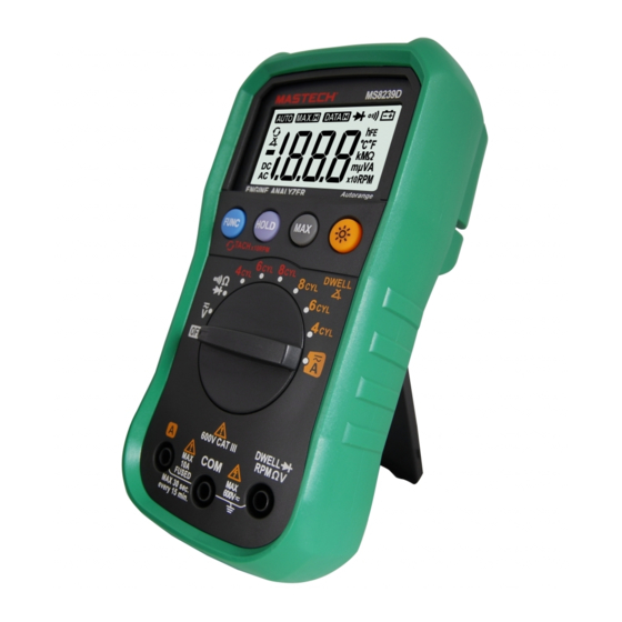
Input Jack 2.1 Names of Components Range Flags (10) Panel (11) Button MS8239D (12) MAX. H Button AUTO MAX. DATA 2.2 Switch, Buttons And Input Jack Elucidation • ON/OFF Button ENGINE ANALYZER This Button is used to the switch of power. -
Page 6: Specifications
3. Specifications 3.2 Electrical Specifications Accuracy is specified for a period of year after calibration Circumstance Temperature: 23 5 ± °C Relative and at 18 °C to 28 °C (64 F to 82 F) with relative humidity ° ° Humidity: < 75%. to 75%. - Page 7 - Input Impedance: 10M Ω 3.2.5 Resistance - Overload Protection: Range Accuracy Resolution 200mV range: 250V DC or AC rms, ±(1.0% of rdg +3 digits) 200Ω 0.1Ω 2V-600V ranges: 600V DC or AC rms. 2kΩ 0.001kΩ - Frequency Range: 40 to 400Hz 20kΩ...
-
Page 8: Operating Instruction
4.4 Function Transform 3.2.8 Engine Rev Put down the "FUNC." when measuring the Range Accuracy current and voltage. Meter will be transformed 4CYL 10RPM between DC and AC range. Put "FUNC." when 3.0% of rdg + 3 digits) measuring the temperature, meter will transform 10RPM ±( 6CYL... -
Page 9: Auto Power Off
4.6 Auto Warning 4.9 Measuring Dc Voltag If the input voltage is larger than 2V at the range WARNING and if the input current is larger than 10A, buzzer will You can't input the voltage which more than have a long sound 600V DC, it's possible to show higher voltage, 4.7 Auto Power Off but it's may destroy the inner circuit. -
Page 10: Measuring Ac Voltage
4.10 Measuring Ac Voltage 4.12 Measuring AC Current WARNING WARNING Shut down the power of the tested circuit, then You can't input the voltage which more than 600V rms connect the meter with the circuit for measurement. AC, it's possible to show higher voltage, but it's may destroy the inner circuit. -
Page 11: Measuring Engine Dwell
4.14 Measuring Engine Dwell 4.16 Testing Diode 413.1 Connect the black test lead to the COM jack and 4.15.1 Connect the black test lead to the COM jack and the red test lead to the INPUT jack. (The polarity the red test lead to the INPUT jack. of red lead is “+”) 4.13.2 Set the transform switch at the desired DWELL 4.15.2 Set the transform switch at the... -
Page 12: Maintenance
Note: • If the input open circuit (or the circuit resistance Replace the Probe measured is higher than 200Ω), then the figure '0L' If insulation on probe is damaged replace it will be displayed. WARNING 5. Maintenance Use meet EN 61010-031 standard, rated CAT III 600V, 10A or better probe.
Need help?
Do you have a question about the MS8239D and is the answer not in the manual?
Questions and answers