Advertisement
Quick Links
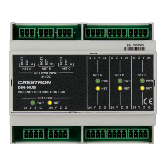
DIN-HUB
DIN Rail Cresnet
Distribution Hub
®
Installation Guide
Description
The DIN-HUB is a DIN rail-mounted Cresnet hub designed to facilitate the con guration of
large Cresnet networks. DIN rail mounting enables modular installation alongside
Crestron
DIN Rail lighting and automation control modules and other third-party DIN rail
®
mountable devices.
DIN-HUB Speci cations
SPECIFICATION
Power Requirements
Cresnet Power Usage
0.6 W (0.03 A @ 24 Vdc)
Maximum Load per Segment
75 W (3.13 A @ 24 Vdc)
Environmental
Temperature
32° to 104 °F (0° to 40 °C)
Humidity
10% to 90% RH (noncondensing)
Heat Dissipation
2 Btu/h
Additional Resources
Visit the product page on the Crestron website (www.crestron.com)
for additional information and the latest rmware updates. Use a QR
reader application on your mobile device to scan the QR image.
Installation
CAUTION: This equipment is for indoor use only. Mount in a well-ventilated area. The
ambient temperature must be 32º to 104 ºF (0º to 40 ºC). The relative humidity must be
10% – 90% (noncondensing).
NOTE: Observe the following points:
• Install and use this product in accordance with appropriate electrical codes and
regulations.
• A licensed electrician should install this product.
NOTE: Before using the DIN-HUB, ensure the device is using the latest rmware. Check
for the latest rmware for the DIN-HUB at www.crestron.com/ rmware. Load the
rmware onto the device using Crestron Toolbox™ software.
The DIN-HUB is designed for installation on a DIN rail. Refer to the following diagram
when installing.
1. Place the top of the DIN-HUB's rail mount over the top of the DIN rail.
2. Tilt the bottom of the DIN-HUB toward the DIN rail until it snaps into place.
NOTE: When mounting DIN rail products, use a at-head screw driver to pull the
DIN rail release tab while snapping the device onto the DIN rail.
To remove the DIN-HUB from the DIN rail, use a small, at object (i.e., a at-head
screwdriver) to pull the DIN rail release tab, and tilt the bottom of the DIN-HUB away from
the DIN rail.
NOTE: Certain third-party DIN cabinets provide space for an informational label
between each DIN rail row. Crestron's Engraver software (version 4.0 or later) can
generate appropriate labels for all Crestron DIN rail products.
Installing the DIN-HUB
DIN rail
release
DETAILS
DIN-HUB
Top
DIN rail
(not supplied)
Hardware Hookup
Make the necessary connections as called out in the illustration below. Apply power after
all connections have been made. When making connections to the DIN-HUB, use a
Crestron power supply.
CAUTION: Insuf cient power can lead to unpredictable results or damage to the
equipment. Please use the Crestron Power Calculator to help calculate how much
power is needed for the system (www.crestron.com/calculators).
NOTE: Use Crestron Certifed Wire. Cresnet HP wire cannot be used.
NOTE: When making connections, strip the ends of the wires approximately 7/16 in
(11 mm). Use care to avoid nicking the conductors. Tighten the connector to 5 in-lb
(0.5 to 0.6 N-m). The wire gauge should be 14 to 26 AWG.
Hardware Connections for the DIN-HUB
NET PWR INPUT:
24 Vdc jumpered from NET HOST
port or external supply. Each port
provides power to a segment.
NET A
NET B
NET C
NET PWR INPUT
24VDC
DIN-HUB
CRESNET DISTRIBUTION HUB
NET HOST
PWR
NET
24 Y Z G
24 Y Z G
NET:
To control system and
other Cresnet devices
NET A:
NET C:
Connect to Cresnet
Connect to Cresnet
devices on segment A
devices on segment C
G
Z
Y
24
G
Z
Y
24
G
NET C
NET A
NET B
PWR
PWR
NET
NET
24 Y Z G
24 Y Z G
24 Y Z G
NET B:
Connect to Cresnet
devices on segment B
Z
Y
24
PWR
NET
Advertisement

Related Manuals for Crestron DIN-HUB


Summary of Contents for Crestron DIN-HUB
- Page 1 To remove the DIN-HUB from the DIN rail, use a small, at object (i.e., a at-head other Cresnet devices devices on segment B screwdriver) to pull the DIN rail release tab, and tilt the bottom of the DIN-HUB away from the DIN rail. NOTE: Certain third-party DIN cabinets provide space for an informational label between each DIN rail row.
- Page 2 CAUTION: Changes or modi cations not expressly approved by the manufacturer responsible for interest in the marks and names of others. Crestron is not responsible for errors in typography or compliance could void the user’s authority to operate the equipment.
Need help?
Do you have a question about the DIN-HUB and is the answer not in the manual?
Questions and answers