Table of Contents
Advertisement
Advertisement
Table of Contents
Troubleshooting

Related Manuals for Vaisala CT25K


Summary of Contents for Vaisala CT25K
- Page 1 CEILOMETER CT25K User’s Guide CT25K-U059en-2.1 26 February 1999 © Vaisala 1999...
- Page 2 © Vaisala 1999 No part of this manual may be reproduced in any form or by any means, electronic or mechanical (including photocopying), nor may its contents be communicated to a third party without prior written permission of the copyright holder.
-
Page 3: Table Of Contents
Ceilometer CT25K CT25K-U059en-2.1 User’s Guide Contents LIST OF FIGURES......................IV INTRODUCTION TO MANUAL ..................VII VALIDITY OF THIS MANUAL ..................VIII SAFETY SUMMARY ......................IX GENERAL INFORMATION..................1 Product Overview ..................1 Specifications ....................3 1.2.1 Mechanical ................... 3 1.2.2 External Connector J1 - Window conditioner ........ - Page 4 Ceilometer CT25K User’s Guide CT25K-U059en-2.1 4.4.1 Data Message No. 1 ..............33 4.4.2 Data Message No. 2 ..............36 4.4.3 Data Message No. 3 ..............38 4.4.4 Data Message No. 4 ..............39 4.4.5 Data Message No. 5 ..............39 4.4.6...
- Page 5 Ceilometer CT25K CT25K-U059en-2.1 User’s Guide 7.1.2 Instructions................. 89 Troubleshooting ..................93 7.2.1 Warnings ..................93 7.2.2 Alarms ..................96 7.2.3 Miscellaneous................97 Failure Diagnosis ..................98 REPAIR ........................99 General......................99 Writing conventions used ................99 Start-up procedure for replacement (all parts) .........100 Transmitter CTT21..................101...
-
Page 6: List Of Figures
Figure 2-4 Attaching the Measurement Unit and the Shield..........13 Figure 2-5 External Connectors (bottom view) ...............15 Figure 2-6 Termination Box Wire Connections ..............16 Figure 3-1 CT25K Switches and LEDs ................20 Figure 4-1 Operation Modes ...................25 Figure 4-2 Open and closed port ..................26 Figure 5-1 Typical Measurement Signal .................49... - Page 7 Ceilometer CT25K CT25K-U059en-2.1 User’s Guide Figure 5-15 CT25039 Wiring Diagram ................72 Figure 5-16 CT3675 Tilt Angle Sensor ................73 Figure 5-17 Window Conditioner CT2614/CT2688 ............74 Figure 5-18 RS Cable..................... 75 Figure 5-19 DMX55 Block Diagram ................76 Figure 5-20 DMX50 Block Diagram ................78 Figure 5-21 DMX611 Block Diagram ................
- Page 8 Ceilometer CT25K User’s Guide CT25K-U059en-2.1 This page intentionally left blank.
-
Page 9: Introduction To Manual
INTRODUCTION TO MANUAL The purpose of this User’s Guide is to be a general information source as well as a detailed operational guide for the user of Ceilometer CT25K. This document is divided into 8 chapters. Chapter 1 offers an overview and technical specifications of the CT25K Ceilometer. -
Page 10: Validity Of This Manual
User’s Guide CT25K-U059en-2.1 VALIDITY OF THIS MANUAL This manual covers ceilometer CT25K in all its configurations as defined by the parts and options listed in section 1.1, running under software revision CT25K- 2.01 or 2.01a Table 1-1 lists the revision history that may apply in comparison to other units... -
Page 11: Safety Summary
LASER SAFETY The CT25K is officially certified as a Class 1 laser device in accordance with European standard EN 60 825-1:1994. It is also classified in accordance with U.S. regulation 21 CFR 1040 as a Class 1 laser device. This means that a... - Page 12 Because of the danger of introducing additional hazards, do not install substitute parts or perform any unauthorized modification to the instrument. Return the instrument to a VAISALA office or authorized Depot for service and repair to ensure that safety features are maintained.
- Page 13 Ceilometer CT25K CT25K-U059en-2.1 User’s Guide Internal Heaters Subassembly can be hot and has the following warning labels: DANGEROUS PROCEDURE WARNINGS Warnings, such as the example below, precede potentially dangerous procedures throughout this manual. Instructions contained in the warnings must be followed:...
- Page 14 Ceilometer CT25K User’s Guide CT25K-U059en-2.1 This page intentionally left blank.
-
Page 15: General Information
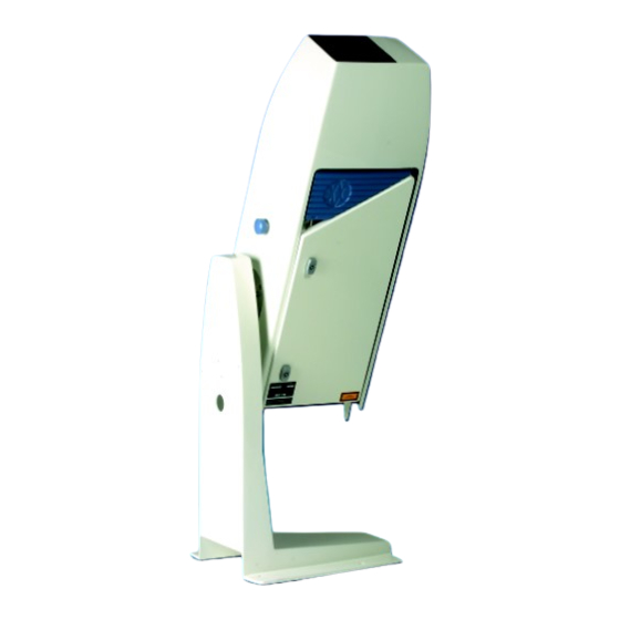
The CT25K is able to detect three cloud layers simultaneously. Besides cloud layers it detects whether there is precipitation or other obstructions to vision. -
Page 16: Figure 1-1 Ceilometer Ct25K
Ceilometer CT25K User’s Guide CT25K-U059en-2.1 Ceilometer CT25K consists of three main parts (Figure 1-1): Measurement Unit including - Optical Subassembly CTB22 - Laser transmitter CTT21 - Receiver CTR21 - Optics Monitor CTL21 - Frame DMF51 including Processor Board DMC50B DC Converter DPS52... -
Page 17: Specifications
Ceilometer CT25K CT25K-U059en-2.1 User’s Guide Shock Absorber CT35022 for ship installations PC Terminal cable CT35198 to connect the connector of the RS-232 port of the PC to the maintenance port Specifications 1.2.1 Mechanical Dimensions: Measurement unit 760 x 280 x 245 mm (30 x 11 x 10 in.) -
Page 18: Output Interface
Ceilometer CT25K User’s Guide CT25K-U059en-2.1 Power connector (J2): Type Binder series 693, 09-4223-00-04 4-pin (male) Mating connector type: Type Binder series 693, 99-4222-70-04 (female) elbow No-break power supply 12V Sealed Lead Acid Battery, 2 Ah Overvoltage Protection Low-press filter , VDR 1.2.4... -
Page 19: Figure 1-2 Data Line Connection Options
Ceilometer CT25K CT25K-U059en-2.1 User’s Guide Standard Character Frame: 1 Start Bit 7 Data Bits Even Parity 1 Stop Bit Standard Character Code: USASCII Pin Connections RD- / AN2Lo Modem Lead A / RxD / RD+ / AN1Hi Modem Lead B / TxD / SD+ / AN1Lo... -
Page 20: External Connector J4 - Maintenance Line
Ceilometer CT25K User’s Guide CT25K-U059en-2.1 1.2.4.2 External Connector J4 - Maintenance line Maintenance line is intended for on-site maintenance and can be used with Ceilometer Maintenance Terminal, PC or other terminal. Connector (J3): Type Binder series 693, 09-4224-06-04 4-pin (male) -
Page 21: Modem Board Dmx50
Compression & error correction: V. 42, V.42bis and MNP 2-5 Adaptive equalization for optimum performance over all lines. 1.2.5.3 ANet™ Interface DMX611 The DMX611 serves as an interface between the CT25K and Vaisala proprietary ANet and INet busses. Baud Rate 2400... -
Page 22: Transmitter
Ceilometer CT25K User’s Guide CT25K-U059en-2.1 1.2.6 Transmitter Laser Source: Indium Gallium Arsenide (InGaAs) Diode Laser Center Wavelength: 905 ± 5 nm at 25 °C (77 °F) Operating Mode: Pulsed Nominal Pulse Properties at Full Range Measurement: 1.6 µWs ± 20% (factory adjustment) -
Page 23: Optical System
Ceilometer CT25K CT25K-U059en-2.1 User’s Guide 1.2.8 Optical System Optics System Focal Length: 377 mm (14.8 in.) Effective Lens Diameter: 145 mm (5.7 in.) Lens Transmittance: 96 % typical Window Transmittance: 98 % typical, clean 1.2.9 Performance Measurement Range: 0...25,000 ft. (0...7.5 km) -
Page 24: Installation
CT25K configuration in question is included in the delivery. Unloading and unpacking The CT25K is shipped in one container containing the Measurement Unit, Shield and Pedestal, and all equipment, accessories and documentation needed for carrying out the installation. Store the original packaging for possible later transport need. -
Page 25: Foundation
Wedge Bolts down; the protruding threads are alternately hammered and tightened a few times so that the Wedge Bolts attach to the hole walls. In case the CT25K replaces a CT12K Ceilometer, the existing foundation and screws can be used. -
Page 26: Assembling The Unit
If the tilt feature will be used (see section 2.4), observe this in the layout of the foundation screws and pedestal placement. Assembling the Unit The CT25K Ceilometer is assembled in four stages: 1. Mount the pedestal on the foundation. 2. Attach the measurement unit to the pedestal. -
Page 27: Figure 2-4 Attaching The Measurement Unit And The Shield
Ceilometer CT25K CT25K-U059en-2.1 User’s Guide Place the measurement unit on the pedestal flange. Attach the pedestal flange to the measurement unit by the two Allen head screws with flat washers. An Allen key is included in the delivery. Figure 2-4 Attaching the Measurement Unit and the Shield 3. -
Page 28: Using The Tilt Feature
CT25K-U059en-2.1 Using the Tilt Feature The Measurement Unit and Pedestal of Ceilometer CT25K are designed so that the unit can operate in a tilted direction. The built-in tilt angle sensor CT3675 detects the tilt angle, i.e. deviation from the vertical. The tilt angle ranges from -15 to +90 degrees from vertical;... -
Page 29: Cable Connections
Ceilometer CT25K CT25K-U059en-2.1 User’s Guide As these advantages are partly contradictory and cannot or need not all be realized, the user must decide the final installation direction. In doing so, the following must be observed: NOTE Unless a tropics window is used, the unit must never be... -
Page 30: Grounding
Ceilometer CT25K User’s Guide CT25K-U059en-2.1 • Remote communication is normally connected to J3. • A local maintenance terminal, for example PSION3, is intended to be connected to J4. A protective cap is included for covering J4 when not in use. -
Page 31: Connection Of Maintenance Terminal
Ceilometer CT25K CT25K-U059en-2.1 User’s Guide The CT25K is equipped with a separate grounding screw on the measurement unit flange for external earthing (see Figure 2-4). CONNECTION SOLID EARTH GROUND INSTALLATION SITE MANDATORY ADEQUATE LIGHTNING AND TRANSIENT PROTECTION. Connection of Maintenance Terminal Any terminal or PC with serial interface and terminal emulation program can be used for operation and maintenance of the CT25K Ceilometer. - Page 32 Exit from "Comms" and select "Save the Setting" from "File" menu by name "CT25K". Now there should be the text "CT25K" under the "Comms" application. From now on PSION3 is ready to communicate with CT25K whenever "CT25K" from the "Comms" application is chosen.
-
Page 33: Start Up
Ceilometer CT25K CT25K-U059en-2.1 User’s Guide START UP Start up procedure Open the unit door; the key is included in the delivery. Make a visual check of the internal connectors, subassemblies, etc. Figure 3-1 describes the switches and LEDs needed to complete the start up procedure. -
Page 34: Figure 3-1 Ct25K Switches And Leds
Ceilometer CT25K User’s Guide CT25K-U059en-2.1 Figure 3-1 CT25K Switches and LEDs... -
Page 35: Mobile Operation Aspects
User’s Guide 3.1.1 Mobile operation aspects The small and lightweight CT25K Ceilometer is suitable also for mobile operation. It has a built-in 12V battery, which enables operation without external power supply for about an hour in normal room temperature. NOTE... -
Page 36: Settings For Normal Operation
Ceilometer CT25K User’s Guide CT25K-U059en-2.1 Settings for Normal Operation Switch settings for normal operation are as follows: Main circuit breaker F1 Window conditioner circuit breaker Battery switch Data message and interface configuration and the configuration of measuring interval and transmission speed are standard factory settings. When required, the settings can be changed by giving commands with the terminal. - Page 37 Ceilometer CT25K CT25K-U059en-2.1 User’s Guide Table 3-1 Factory parameter settings Response to User’s Menu Standard factory Notes commands... settings of User’s Menu parameters CEILO>get..data_acq AUTOADJUSTMENTS: DATA-ACQ. INTERVAL: 15 SEC. 15... 120 seconds available RECEIVER GAIN: BANDWIDTH: SAMPLING RATE: 10 MHz...
- Page 38 Ceilometer CT25K User’s Guide CT25K-U059en-2.1 ...oper_mode OPERATION MODE: CONTINUOUS Option STANDBY requires command START for carrying out each cycle. …options INSTALLED Modem name is: DMX55, DMX50 [MODEM NAME] or DMX611 INACTIVE ACTIVE SKY CONDITION: ACTIVE HUMITTER: INACTIVE INACTIVE BLOWER: ACTIVE ...
-
Page 39: Operation
Ceilometer CT25K CT25K-U059en-2.1 User’s Guide OPERATION Operation Modes There are two operation modes, continuous i.e. normal and standby. Commands OPER_MODE STANDBY and OPER_MODE CONTINUOUS are used to switch between the modes. In NORMAL mode continuous measurement and message transmission occurs according to chosen parameters. -
Page 40: Figure 4-2 Open And Closed Port
Ceilometer CT25K User’s Guide CT25K-U059en-2.1 CLOSED Measurement data message transmitting state. In this state messages are transmitted automatically at predetermined intervals, or as a response to a polling input string, depending on the corresponding settings. User commands are not accepted, except command OPEN, which turns the line into the OPEN state. -
Page 41: User Commands
Ceilometer CT25K CT25K-U059en-2.1 User’s Guide User Commands User commands, command hierarchy and description are described in table 4- 1 below. User commands are accessible after opening the line by command OPEN (no password needed). The command line interpreter provides interactive help support, so that the exact format of commands doesn’t have to be remembered. - Page 42 Ceilometer CT25K User’s Guide CT25K-U059en-2.1 Table 4-1 List of user and advanced level commands. Advanced level commands are marked bold. 1st (TOP) 2nd LEVEL 3rd LEVEL 4th LEVEL 5th LEVEL DESCRIPTION LEVEL CLOSE Release port for message transmission, i.e. abort command dialog...
- Page 43 Ceilometer CT25K CT25K-U059en-2.1 User’s Guide 1st (TOP) 2nd LEVEL 3rd LEVEL 4th LEVEL 5th LEVEL DESCRIPTION LEVEL MESSAGE ANGLE_COR Angle correction: Cloud and vertical visibility heights (distances) in messages are NOT corrected for the tilt angle Angle correction: Cloud and vertical visibility heights (distances) in...
- Page 44 Ceilometer CT25K User’s Guide CT25K-U059en-2.1 1st (TOP) 2nd LEVEL 3rd LEVEL 4th LEVEL 5th LEVEL DESCRIPTION LEVEL OPER_MODE COMP_MONIT Run internal crosstalk compensation monitor until ESC CONTINUOUS Operation Mode: Continuous measurement mode STANDBY Standby mode, no measurement unless commanded by START...
- Page 45 Ceilometer CT25K CT25K-U059en-2.1 User’s Guide 1st (TOP) 2nd LEVEL 3rd LEVEL 4th LEVEL 5th LEVEL DESCRIPTION LEVEL BAUD B300 Set data port serial line baud rate to 300 B1200 Set data port serial line baud rate to 1200 B2400 Set data port serial line baud rate to 2400...
- Page 46 Ceilometer CT25K User’s Guide CT25K-U059en-2.1 1st (TOP) 2nd LEVEL 3rd LEVEL 4th LEVEL 5th LEVEL DESCRIPTION LEVEL VALUE TEMPERATURE BLOWER Print value of measured blower temperature, units: °C Print value of measured CPU board temperature, units: °C LASER Print value of measured laser temperature, units: °C LENS Print value of measured temperature adjacent to lens, units: °C...
-
Page 47: Data Messages
Ceilometer CT25K CT25K-U059en-2.1 User’s Guide Data Messages The following standard messages are provided: Data message No. 1, 2, 3, 6 and 7. ANet / INet communication with DMX611. Status message S. Each port can be set to transmit a specified message automatically. - Page 48 Ceilometer CT25K User’s Guide CT25K-U059en-2.1 Interpretation of the message is as follows : 1ST LINE Example: (CTA2010J↵ where Start-of-Heading character Ceilometers’ identification string; always CT Unit number 0...9, A...Z Software level id 00...99 Message number; this message is always = 1...
- Page 49 Ceilometer CT25K CT25K-U059en-2.1 User’s Guide FEDCBA98 Alarm (A), Warning (W), and internal status information. Each character is a hexadecimal representation of four bits, altogether 32 bits (b00-b31), with the following breakdown. Interpretation as follows: Laser temperature shut-off (A) Laser failure (A)
-
Page 50: Data Message No. 2
Ceilometer CT25K User’s Guide CT25K-U059en-2.1 4.4.2 Data Message No. 2 Data message no. 2 contains the range and sensitivity normalized backscatter profile within a range of 0..25000 ft, which makes it suitable for e.g. graphical plotting of the atmosphere. Data resolution is 100ft = 30 m with distance, and 16 bits (four hex-ASCII characters) with signal magnitude. - Page 51 Out-of-Range is indicated by slashes (/////). Contents: Parameter SCALE, 100 (%) is normal (0...999 possible) measurement mode; N = Normal, (C = Close range, not available in CT25K) laser pulse energy, % of nominal factory setting (0...999) laser temperature degrees C (-50...+99) receiver sensitivity, % of nominal factory setting (0...999)
-
Page 52: Data Message No. 3
This message contains a line which has one bit for each range gate at 100 ft resolution. It is intended for printer-type black-and-white graphical recorders such as Vaisala DR21, DR23, DD50 with printer, etc. The message is derived from Message no. 2 by setting a threshold for the range and sensitivity normalized backscatter profile and reporting signal exceeding this threshold as a 1, and otherwise as a 0. -
Page 53: Data Message No. 4
Ceilometer CT25K CT25K-U059en-2.1 User’s Guide 999 minimizes the threshold, and thus, maximizes recording sensitivity to a backscatter value of 100 / (10,000 km srad). 4TH LINE Identical to the 3rd line of message no. 3. 4.4.4 Data Message No. 4 Data message no. -
Page 54: Data Message No. 7
Ceilometer CT25K User’s Guide CT25K-U059en-2.1 The second number of line: Height of the 1st cloud layer (5 500 ft or 550 m depending on feet or meter selection) The third number of line: Cloud amount of the 2nd layer in oktas... -
Page 55: Spare)
The DMX611 serves as an interface between CT25K buss structure and Vaisala proprietary ANet and INet busses. The DMX611 converts CT25K data into binary format. After receiving a poll request, the DMX611 sends an answer packet containing the requested CT25K data. While both the poll and answer messages are in hexadecimal binary format, the user interface is offered by the Testset. -
Page 56: Status Message "S
Ceilometer CT25K User’s Guide CT25K-U059en-2.1 4.4.11 Status Message "S" The Status Message displays internal monitoring of the whole unit including prevailing parameter values voltages, receiver transmitter, temperatures, environmental factors, and internal heating. The message is meant mainly for testing and maintenance purposes. The Status Message is displayed by the command GET STATUS. - Page 57 Ceilometer CT25K CT25K-U059en-2.1 User’s Guide LINES 3...6 Measured internal voltages in units of 0.1V, as follows: Battery voltage, e.g. Battery charge voltage, e.g. Internal raw voltage, e.g. Receiver high voltage, e.g. 2306 Rec. switcher feedback voltage, e.g. Transmitter high voltage, e.g.
- Page 58 Ceilometer CT25K User’s Guide CT25K-U059en-2.1 LINES 15...20 Temperature and environment variables as follows: TEMPERATURE BLOWER +20C Temperatue measured at the Window Conditioner blower airfow exit, e.g. +20 deg C +34C Temperature on the microprocessor (CPU) Board, e.g. +34 deg C...
-
Page 59: Manual Message
The polling string can contain the message identification. The CT25K unit can be assigned an identification of one character digit or letter. The factory setting is 0 (zero). The polling mode is activated with the command: SET MESSAGE MODE POLLING CEILO>... -
Page 60: Prevailing Parameter Settings
NOTE If the id character in a polling string is replaced with a blank space, all ceilometers on the line will respond. Accordingly, if No is a blank space, CT25K sends the default message. Prevailing parameter settings The prevailing control and parameter settings that chiefly determine operation can be seen by the following GET commands. -
Page 61: Manual Angle Setting
Ceilometer CT25K CT25K-U059en-2.1 User’s Guide GET FACTORY CEILO> FACTORY BEAMSPLITTER: 96% IN LASER: 185 OUT LASER: 1200 COARSE COMP.: 13 FINE COMP.: 125 RECEIVER TEST VALUE: 350 CLEAN WINDOW: 200mV GET MESSAGE CEILO> MESSAGE ANGLE CORRECTION: ON HEIGHT OFFSET: 0... - Page 62 Ceilometer CT25K User’s Guide CT25K-U059en-2.1 GET STATUS CEILO> VOLTAGES (UNIT 0.1V) P12 130 M12 -122 P5G 53 M5G -54 VCA 220 P13 126 M13 -121 P5R 49 M5R -48 BAT 121 P18 176 PHV 2755 PFB 20 P65 769 CHA 121...
-
Page 63: Functional Description
Theory of Operation Basic Principle of Operation The operating principle of the CT25K Ceilometer is based on measurement of the time needed for a short pulse of light to traverse the atmosphere from the Transmitter of the Ceilometer to a backscattering cloud base and back to the Receiver of the Ceilometer. - Page 64 User’s Guide CT25K-U059en-2.1 In its normal full-range operation the CT25K ceilometer digitally samples the return signal every 100 ns from 0 to 50 µs, providing a spatial resolution of 50 feet from ground to 25,000 feet distance. This resolution is adequate for measuring the atmosphere, since visibility in the densest clouds is in the order of 50 feet.
- Page 65 Ceilometer CT25K CT25K-U059en-2.1 User’s Guide Height Normalization Assuming a clear atmosphere, it can be seen that the power is inversely proportional to the square of the distance or height i.e., the strength of a signal from 10,000 ft is generally one-hundredth of that from l,000 ft.
- Page 66 The CT25K uses a contrast threshold value which, through many tests, has been found to give Vertical Visibility values closest to those reported by ground-based human observers. A wide safety margin is obtained with regard to pilots looking down in the same conditions since the contrast objects, especially runway lights, are much more distinct on the ground.
-
Page 67: Technical Description
Ceilometer CT25K CT25K-U059en-2.1 User’s Guide Technical Description 5.2.1 General Figure 5-2 below shows the internal layout of the Measurement Unit and the following figure 5-3 the subassembly interconnections. Summary of part num- bers and subassemblies is listed in Table 5-1. The technical description is split into subparagraphs according to Unit Block Diagram illustrated in Fig. -
Page 68: Figure 5-3 Subassembly Interconnections
Ceilometer CT25K User’s Guide CT25K-U059en-2.1 Figure 5-3 Subassembly Interconnections Table 5-1 Parts List PART NO. DESCRIPTION NOTES CT15035 ENCLOSURE CT35042 STANDARD WINDOW CT35043 TROPICS WINDOW Specified at order CTP241 LINE & PWR INTERFACE SUBASSEMBLY, AC 4592 BATTERY... -
Page 69: Lidar Measurement
Ceilometer CT25K CT25K-U059en-2.1 User’s Guide CT25039 INTERNAL HEATERS SUBASSEMBLY CT3675 TILT ANGLE SENSOR CTB22 OPTICAL SUBASSEMBLY CTT21 LASER TRANSMITTER CTR21 RECEIVER CTL21 OPTICS MONITOR CT25015 COMPENSATION FIBER DMF51 BOARD FRAME DMC50B PROCESSOR BOARD DPS52 DC CONVERTER BOARD DCT51 CEILOMETER INTERFACE BOARD... -
Page 70: Figure 5-4 Block Diagram Of Operational Units
Ceilometer CT25K User’s Guide CT25K-U059en-2.1 Normal (full range) mode characteristics: Laser pulse 100 ns Energy 1.6 µ J Repetition rate 5.57 kHz Number of pulses 65,536 Measurement time 11.7 s Receiver on High Gain Bandwidth 3 MHz Sampling at 100 ns 500 useful samples per laser pulse, Measurement range 0...25,000 ft. - Page 71 Ceilometer CT25K CT25K-U059en-2.1 User’s Guide When the measurement starts, the Timing and Control logic of the DCT51 starts issuing trigger pulses to the Laser Transmitter CTT21 at the specified repetition rate. At each trigger pulse the transmitter sends out one laser pulse.
-
Page 72: Internal Monitoring And Control
Ceilometer CT25K User’s Guide CT25K-U059en-2.1 thus the resulting distortion is visible to the software in the raw measurement profile, and this is iteratively kept within limits. 5.2.3 Internal Monitoring and Control All essential subassembly functions are monitored continuously to ensure measurement accuracy and reliability. -
Page 73: Laser Transmitter Ctt21
Ceilometer CT25K CT25K-U059en-2.1 User’s Guide Description The optical subassembly consists of the following major units: the conical optical tube with fixture for the lens, a precise beam integrator block at the lower end including a beamsplitter and a narrow-band filter, and a connection flange for the laser transmitter and receiver subassemblies. -
Page 74: Receiver Ctr21
Ceilometer CT25K User’s Guide CT25K-U059en-2.1 small control circuit with a temperature sensor and a heating element ensures the correct laser temperature. The laser temperature is also routed to the Ceilometer Interface Board DCT51 and Processor Board DMC50B for internal monitoring. -
Page 75: Optics Monitor Ctl21
Ceilometer CT25K CT25K-U059en-2.1 User’s Guide the flash AD converter. The gain control as well as the bandwidth selection are automatic and controlled by the processor software and the DCT51. WARNING Dangerous voltages are present in this instrument. Use extreme caution when handling, testing, and adjusting. -
Page 76: Board Frame Dmf51
Ceilometer CT25K User’s Guide CT25K-U059en-2.1 delivers a control signal for the heating via an amplifier, processor board A- to-D Converter, and software. 5.3.5 Board Frame DMF51 The frame DMF51 is a subassembly into which the Processor Board DMC50B, Ceilometer Interface Board DCT51, DC Converter DPS52 and the optional modem are plugged. -
Page 77: Processor Board Dmc50B
Ceilometer CT25K CT25K-U059en-2.1 User’s Guide The connections between the separate plug-in boards are realized by means of a motherboard and multiple board connectors. 5.3.6 Processor Board DMC50B Figure 5-10 DMC50B Block Diagram... - Page 78 Ceilometer CT25K User’s Guide CT25K-U059en-2.1 The DMC50B Processor Board is the central processing unit of the CT25K. It performs the following functions: A-to-D conversion of signals from various internal sensors Data processing under a powerful real-time operating system Serial communication with external devices...
- Page 79 2 configurable ports to comply with: RS-232D, RS-422, RS-423, and RS- 485 or MIL-STD-188-114 standards Data Transfer Rate 110 to 19,200 baud 300 to 9600 baud used in CT25K Programmable rate, frame, handshake and port standard Electrostatic Discharge Protection 8 kV per each port pin Overvoltage protection bipolar 30 A (1 ms) TRANSZORBS™...
-
Page 80: Figure 5-11 Dip Switch Settings Of The Dmc50
Ceilometer CT25K User’s Guide CT25K-U059en-2.1 See Figure 5-11 and Table 5-2 for DMC50 DIP switch settings. Figure 5-11 DIP Switch Settings of the DMC50 Table 5-2 DIP Switch Settings of the DMC50 Board Switch position Switch setting Function DMC50 S2-1... -
Page 81: Dc Converter Dps52
5.3.7 DC Converter DPS52 The DPS52 DC Converter is an efficient and self-monitoring power distributor board specially designed for the CT25K. Having five independent switch-mode voltage converters the board is capable of delivering up to 20W. Figure 5-12 shows the block diagram of DC Converter DPS52. - Page 82 Ceilometer CT25K User’s Guide CT25K-U059en-2.1 All these voltages are normally supplied by two 18VAC windings. The second supply rectified from two 10VAC windings is reserved for internal battery charger, heating power for transmitter and inheater and outheater control relays. All voltage and two temperature channel measurements along with several internal and external functions are controlled by a two-wire serial I C bus.
-
Page 83: Ceilometer Interface Board Dct51
Ceilometer CT25K CT25K-U059en-2.1 User’s Guide Output voltages: Signal name Acceptable Nominal Range (V) current(A) 5.0 .. 5.8 0.15 -5.8 .. –5.0 0.05 +5VDISC 5.0 .. 5.8 0.45 +18V 16.0 .. 18.5 0.010 +12V 12.0 .. 13.5 -12V -13.5 .. -11.5 +65V 60 .. -
Page 84: Line And Power Interface Subassembly Ctp241
Ceilometer CT25K User’s Guide CT25K-U059en-2.1 backscatter signal detected by the photodiode in the receiver is sampled in real-time in this subassembly at the speed equal to that of the light beam in the atmosphere sent from the laser transmitter. All Range Gates are sampled at each laser pulse and digitized by means of the 8-bit flash A-to-D converter. -
Page 85: Figure 5-14 Ctp241 Wiring
Ceilometer CT25K CT25K-U059en-2.1 User’s Guide Figure 5-14 CTP241 Wiring Line voltage selection 100...115 VAC or 220...240 VAC is carried out in the CTP241 by an internal switch, the setting of which is written on the label on the subassembly. This setting also accomplishes the series vs. parallel connection of Internal Heater resistors. -
Page 86: Internal Heaters Subassembly Ct25039
Ceilometer CT25K User’s Guide CT25K-U059en-2.1 5.3.10 Internal Heaters Subassembly CT25039 Figure 5-15 CT25039 Wiring Diagram The Internal Heaters subassembly CT25039 increases the temperature in the area of the optical subassembly to prevent the lens and the measurement unit window from becoming wet or misty. At the same time it also keeps the whole interior above condensation temperature. -
Page 87: Tilt Angle Sensor Ct3675
Ceilometer CT25K CT25K-U059en-2.1 User’s Guide Thermal switches (K1, K2): switch temperature 95 - 105°C nominal current 2.5A operating voltage 250VAC 5.3.11 Tilt Angle Sensor CT3675 The built-in tilt angle sensor CT3675 enables accurate cloud base measurements in a tilted direction. See section 2.4 for information about alternatives on how to use the tilt feature. -
Page 88: Window Conditioner Ct2614 / Ct2688
Ceilometer CT25K User’s Guide CT25K-U059en-2.1 5.3.12 Window Conditioner CT2614 / CT2688 Figure 5-17 Window Conditioner CT2614/CT2688... -
Page 89: Maintenance Terminal Psion3 (Option)
20 hours. The RS232 interface RS cable has a standard 9 pin connector illustrated in figure 5-18. The RS cable is connected to Terminal cable CT3840 which is connected to the CT25K’s maintenance line connector J4. Figure 5-18 RS Cable... -
Page 90: Modem Dmx55 (Option)
The operation mode of the modem is set at the factory. Over a fixed point-to-point line the modem can be operated in an ANSWER or an ORIGIN mode. The modem supports different standards such as V.21, V.23 and Bell 103/202. The CT25K options are ITU-T V.21 and Bell 103. - Page 91 Indicator relay closed Modem Ready Connector layout The internal signal routing of the CT25K connects the modem outputs to connector J3. For further details, refer to the wiring diagrams. The front panel is provided with the following connections. 6-pin RS232 Connector (P2)
-
Page 92: Modem Dmx50 (Option)
Line In/Out - when standard 2-wire connection is used or only Line Out at separate wire for transmission and reception +LOOP Power supply + (not used in CT25K) -LOOP Power supply - (not used in CT25K) 5.3.15 Modem DMX50 (Option) - Page 93 Ceilometer CT25K CT25K-U059en-2.1 User’s Guide Safety precautions Before delivery, the DMX50 modem is tested at the factory for operation and safety. The following safety precautions, however, must be taken into account: WARNING Open data lines can have a static charge. Handle the connection wires especially carefully, do not touch them during a thunderstorm.
-
Page 94: Dmx611 Anet™ Interface (Option)
This LED will flash at two flashes per second, indicating the iSi portion of the DMX611 is actively executing code. This LED will flash as the DMX611 receives data from the CT25K (or from any device attached to the front panel RxD input). - Page 95 The phone jack will allow communication to the CT25K via the iSi. To verify proper operation of the DMX611, the phone jack will also allow direct Inet communication to the Router, iSi and the front panel isolated Inet connection.
- Page 96 Ceilometer CT25K User’s Guide CT25K-U059en-2.1 20 CASE Case Ground DIP Switch Settings (Router Node ID) (iSi Device ID) S1:1 LSB - Node ID S2:1 LSB – Device ID S1:2 S2:2 S1:3 S2:3 S1:4 S2:4 MSB - Device ID S1:5 S1:6...
-
Page 97: Sky Condition Algorithm
Sky Condition Algorithm 5.4.1 General The CT25K sky condition algorithm uses a time series of ceilometer data to calculate the cloud cover and the heights of different cloud layers. The algorithm is based on so-called Larsson algorithm, developed by Swedish Air Force and Swedish Hydrological Institute (SMHI), but further modified at Vaisala. -
Page 98: Algorithm Overview
Ceilometer CT25K User’s Guide CT25K-U059en-2.1 Then select the sky condition message type (msg6 or msg7) to be reported: CEILO>set message type msg6 MESSAGE TYPE: 6 CEILO>close NOTE It is recommended to use a 15 or 30 seconds data acquisition interval with the sky condition option. - Page 99 Ceilometer CT25K CT25K-U059en-2.1 User’s Guide The counts are summed starting from the lowest bin. The bins where the sum exceeds 1/33, 3/8, 5/8 and 7/8 of the maximum value are recorded as layer heights. The corresponding cloud amounts for these layers are 1,3,5 and 7 oktas.
- Page 100 Ceilometer CT25K User’s Guide CT25K-U059en-2.1 Overcast (8 oktas) is reported if all the measurements during the last 30 minutes have a hit. Overcast height is assigned according to the bin where 14/15 of the total count value is exceeded. However, overcast is not reported if there are "weak hits" during the latest 15 minutes period.
-
Page 101: Periodic Maintenance
Ceilometer CT25K CT25K-U059en-2.1 User’s Guide 6. PERIODIC MAINTENANCE Periodic maintenance is normally limited to window cleaning. In addition, Warnings and Alarms should be checked regularly with the maintenance terminal or another terminal or PC with serial connection (See paragraph 4.4.11 Status Message “S”). Proper function of the Window Conditioner air blower, the only mechanically moving part, should also be checked. -
Page 102: Battery Check
Ceilometer CT25K User’s Guide CT25K-U059en-2.1 The door of the measurement unit utilizes an electrically conductive rubber gasket to suppress electromagnetic radiation. When the door is opened, check that the gasket and the opposite contact surface are clean. Use wet cloth for cleaning if necessary. -
Page 103: Troubleshooting
7.1 Normal Operation 7.1.1 Equipment To check the normal operation of the CT25K you need to have a maintenance terminal which can be a PSION3 palmtop computer with an RS cable (RS232 Interface) and Terminal Cable CT3840 or a PC with serial interface, PC Terminal Cable CT35198, and any terminal program. - Page 104 Ceilometer CT25K User’s Guide CT25K-U059en-2.1 Press ENTER. The prompt "CT:"should appear on the screen. If not, check the cables and port settings (see CT-VIEW User’s Guide). 4. Check that the operation of the ceilometer starts normally, as follows: After power-up routines, the MEAS LED D4 (LED = Light Emitting Diode) on the DCT51 board periodically lights 12 seconds and the cycle is repeated according to the programmed data acquisition interval.
- Page 105 Ceilometer CT25K CT25K-U059en-2.1 User’s Guide 6. Check the status message. All the VOLTAGES, RECEIVER and TRANSMITTER values are within predefined limits if no asterisks (*) appear. An asterisk in front of a variable indicates that an alarm or warning limit of that variable is exceeded.
- Page 106 Ceilometer CT25K User’s Guide CT25K-U059en-2.1 (0080 0000) Window contaminated (W) (0040 0000) Battery low (W) (0020 0000) Laser power low (W) (0010 0000) Laser temperature high or low (W) (0008 0000) Internal temperature high or low (W) (0004 0000) Voltage high or low (W) (0002 0000) Relative Humidity is >...
-
Page 107: Troubleshooting
The purpose of this troubleshooting is to locate the problem. If a damage is suspected in a subassembly or a board, replace it with a spare part and send the defective part to Vaisala for repair. NOTE Replacements have to be done according to instructions given in the Instructions for Replacement of Parts in section 8 and are allowed for trained personnel only. - Page 108 Ceilometer CT25K User’s Guide CT25K-U059en-2.1 Battery low warning The unit has been Connect the line voltage or replace powered too long the battery using the backup battery Recharging of the If the battery is old, replace it. battery fails If the battery is OK, check the operation of the DPS52 DC Converter.
- Page 109 Ceilometer CT25K CT25K-U059en-2.1 User’s Guide Relative humidity > 85 Water has been Take the ceilometer inside, open the % warning (option) condensed inside the maintenance door and let it dry in a ceilometer. Leakage warm air conditioned place. in the enclosure or...
-
Page 110: Alarms
Ceilometer CT25K User’s Guide CT25K-U059en-2.1 7.2.2 Alarms Problem Reason Instructions Laser temperature shut- Direct sunlight Direct sunlight can burn the laser diode. Use Tropics window or turn the ceilometer away. Environment Do not operate the ceilometer. temperature too high Laser failure... -
Page 111: Miscellaneous
Ceilometer CT25K CT25K-U059en-2.1 User’s Guide 7.2.3 Miscellaneous Problem Reason Instructions DPS52 Power OK LED Power is not Check that both the main and the battery (D2) is not lit connected switches are in ON position. Check the presence and correctness of the line voltage. -
Page 112: Failure Diagnosis
Ceilometer CT25K User’s Guide CT25K-U059en-2.1 7.3 Failure Diagnosis In case of malfunction do the following: 1. Check the cable connections (see 2.5). 2. Check the presence and correctness of the line voltage. 3. Check the operation states of the LEDs in the unit (see 3.1). -
Page 113: Repair
User’s Guide 8. REPAIR 8.1 General Replacing a subassembly comes into question when there is reason to suspect that malfunction of the Ceilometer CT25K is caused by a fault in that subassembly. CAUTION Servicing the equipment must be performed by qualified personnel. -
Page 114: Start-Up Procedure For Replacement (All Parts)
Replacement can be done outdoors even in the presence of light precipitation but in this case take care that the removed subassembly remains dry and no water gets into the interior of the Ceilometer CT25K. However, if adjustment is needed after replacement then that must be done in clear weather conditions or indoors using the Optical termination hood (CT25184). -
Page 115: Transmitter Ctt21
Ceilometer CT25K CT25K-U059en-2.1 User’s Guide Refer to Figure 8-1 for cable connections of the subassemblies. Figure 8-1 Board Connectors of the DMF51 Board Frame 8.4 Transmitter CTT21 8.4.1 Removal WARNING The laser diode at Laser Transmitter CTT21 emits invisible laser power which is harmful to the eye if viewed at short distance. -
Page 116: Replacement
- do not apply force to the Transmitter because it may disturb the centering. Take the Transmitter in your hand. 3. Deliver the entire Transmitter to Vaisala. Figure 8-2 Removing the Laser Transmitter 8.4.2 Replacement To replace a Laser Transmitter CTT21 (Note Paragraph 8.3 Start-up... - Page 117 Ceilometer CT25K CT25K-U059en-2.1 User’s Guide Check that the transmitter is now in the correct position, that is, the sides of the transmitter case are approx. parallel with the edges of the lower part of the Optical Subassembly. If this is not the case, loosen the attachment ring first, then correct the transmitter position and fasten as described above.
- Page 118 Ceilometer CT25K User’s Guide CT25K-U059en-2.1 Wait until a few measurement cycles have been completed, and the new value has been updated in the status message. Give the command GET STATUS↵ g) Check from the status message under the title Transmitter that the IN value of the transmitter in question equals the Calibration Factor.
-
Page 119: Compensation Adjustments
Ceilometer CT25K CT25K-U059en-2.1 User’s Guide 8.4.3 Compensation adjustments Internal crosstalk compensation must be adjusted after a transmitter, a receiver or an optics monitor has been replaced or if the compensation fiber has been replaced. Adjustment should be done in clear weather conditions or indoors using the Optical termination hood (CT25184). -
Page 120: Figure 8-3 Adjusting The Compensation
– Compensation Fiber itself is defective – Receiver is damaged – Beamsplitter at the lower end of the Optical Subassembly is broken etc. In the latter case consult Vaisala. 4. Press the Esc key one or two times to stop the compensation monitoring. -
Page 121: Figure 8-4 Adjusting The Compensation
Ceilometer CT25K CT25K-U059en-2.1 User’s Guide Figure 8-4 Adjusting the compensation 5. Set the autoadjustments on with the following command: SET DATA_ACQ AUTOADJ ON↵ 6. Wait for some minutes. Give the command GET STATUS↵ Check from the status message under the title Receiver that the COMP values, which are fine adjusted by the software, are close to the original 13 (Coarse) and 125 (Fine). -
Page 122: Receiver Ctr21
Receiver begins to move along, stop it by hand. The photo diode has been centered at the factory - do not apply force to the Receiver because that may disturb the centering. Take the receiver into your hand and detach the Coaxial Cable from it. 5. Send the defective receiver to Vaisala. -
Page 123: Replacement
Ceilometer CT25K CT25K-U059en-2.1 User’s Guide Figure 8-5 Removing the Receiver 8.5.2 Replacement To replace Receiver CTR21 (Note Paragraph 8.3 Start-up procedure): 1. Attach the Coaxial Cable to connector J2 at the receiver. Note the marked ends of the cable. 2. Take the Receiver into your hand and set it in place. Note the right position, the ribbon and coaxial cables come out from the back side. - Page 124 Ceilometer CT25K User’s Guide CT25K-U059en-2.1 Check that the receiver is now in the correct position, that is, the long edges of the receiver case are approx. horizontal. If this is not the case, loosen the attachment ring first, then correct the receiver position and fasten as described above.
-
Page 125: Coaxial Cable Replacement
Ceilometer CT25K CT25K-U059en-2.1 User’s Guide Check that the SENS value is OK. The receiver sensitivity tells you the present measured receiver value compared to the factory setting. If the SENS value is OK, the receiver installation is ready and you can skip steps g) and h). -
Page 126: Replacement
Ceilometer CT25K User’s Guide CT25K-U059en-2.1 2. Detach the Ribbon Cable Connector of the Receiver from the connector J11 at the DMF51 Board Frame. Refer to Figure 8-1. 3. Detach the Coaxial Cable from the DCT51 front panel. 4. Loosen the CTR21 Receiver attachment ring (See Figure 8-5) using a 2.5 mm hexagon key as a lever;... -
Page 127: Compensation Fiber
Ceilometer CT25K CT25K-U059en-2.1 User’s Guide 8.6 Compensation Fiber 8.6.1 Compensation Fiber replacement The Compensation fiber is made from optical fiber. Handle the fiber with care. Don’t twist. Do not allow the ends of the fiber to be contaminated by grease or dust. -
Page 128: Optics Monitor Ctl21
2. Mark (with pencil) the position of the CTL21 in order to replace it correctly. 3. Loosen the two screws (Figure 8-6) with a screwdriver. (The optics monitor ribbon cable remains attached to the Optical Subassembly). 4. Send the defective Optics Monitor to Vaisala. -
Page 129: Replacement
Ceilometer CT25K CT25K-U059en-2.1 User’s Guide Figure 8-6 Removing the Optics Monitor 8.7.2 Replacement To replace Optics Monitor CTL21: 1. Fasten the Optics Monitor CTL21 to the Ceilometer with two screws (Figure 8-6). The previous horizontal position of the CTL21 is a good estimate of the correct position. -
Page 130: Boards Of Board Frame Dmf51
Ceilometer CT25K User’s Guide CT25K-U059en-2.1 8.8 Boards of Board Frame DMF51 The boards of Board Frame DMF51 are shown in Figure 8-7. Replacement of boards does not require parameter settings except the Ceilometer Interface Board DCT51, the adjustments of which are described in Paragraph 8.8.2.1. -
Page 131: Replacing Boards
Ceilometer CT25K CT25K-U059en-2.1 User’s Guide 8.8.2 Replacing boards 1. Plug the new board carefully into the corresponding slot (Figure 8-7). 2. Attach the new board with the two screws. Then plug in connectors. Cable connections were described in paragraph 2.5. - Page 132 Line), if the cap is attached. (All cables must be disconnected from the External Connectors J1-J4). 3. There are 6 screws at the bottom of the CT25K that are situated around the rectangular opening of external connectors J1...J4 (See Figure 8-8).
-
Page 133: Replacement
Ceilometer CT25K CT25K-U059en-2.1 User’s Guide Figure 8-8 Removing Line and Power Interface Subassembly CTP241 8.9.2 Replacement WARNING The Line & Power Subassembly contains dangerous voltage of 115 VAC/230 VAC even when the Power Switch F1 is turned off. Do not connect the Power Cable to an unmounted Line &... -
Page 134: Internal Heater Subassembly Ct25039 Replacement
Ceilometer CT25K User’s Guide CT25K-U059en-2.1 7. Turn the 6 screws at the bottom of the CT25K clockwise (Figure 8-8) and push then slightly until they go through the holes in the gasket of the connector flange. Then tighten the screws normally. -
Page 135: Battery 4592 Replacement Instructions
Ceilometer CT25K CT25K-U059en-2.1 User’s Guide Figure 8-9 Internal heater replacement 8.9.4 Battery 4592 replacement instructions 1. Open the screw from the battery switch subassembly front panel shown in Figure 8-10 and remove the panel. 2. Pull the battery out by the plastic stripe attached around the battery. Do not pull by the battery switch connector wires. -
Page 136: Figure 8-10 Battery Replacement
Ceilometer CT25K User’s Guide CT25K-U059en-2.1 Figure 8-10 Battery replacement... -
Page 137: Index
Ceilometer CT25K CT25K-U059en-2.1 User’s Guide INDEX CPU Board............. 63 CT-VIEW ............89 Alarm check ...........87 Alarms Laser failure ..........96 Dangerous procedure warnings......xi Laser temperature shut-off......96 Data messages..........33 Receiver failure ..........96 Data message No. 1 ........33 Voltage failure..........96 Data message No. - Page 138 Password ............27 Battery check ..........88 PC terminal cable ..........3 Maintenance terminal PSION3 Performance ............. 9 Connecting PSION3 to CT25K ....18 Periodic maintenance........87 Operation........... 18 Pin connections ..........5, 6 Port settings ..........76 PIN photodiodes..........61 PSION3 .............
- Page 139 Ceilometer CT25K CT25K-U059en-2.1 User’s Guide Pulse properties ..........8 In the tropics..........14 Transimpedance amplifier ......60 Transmitter ............8 Transmitter CTT21 ........59 Receiver ............8 Receiver CTR21 ..........60 Calibration factor........103 Removal ..........101 Coaxial cable replacement ......111 Replacement ..........102 Removal ...........108...
Need help?
Do you have a question about the CT25K and is the answer not in the manual?
Questions and answers