Table of Contents
Advertisement
Quick Links
Advertisement
Table of Contents
Troubleshooting

Related Manuals for Vaisala CL31


Summary of Contents for Vaisala CL31
- Page 1 USER'S GUIDE Vaisala Ceilometer CL31 M210482EN-D...
- Page 2 The contents are subject to change without prior notice. Please observe that this manual does not create any legally binding obligations for Vaisala towards the customer or end user. All legally binding commitments and agreements are included exclusively in the applicable supply contract or Conditions of Sale.
-
Page 3: Table Of Contents
Regulatory Compliances ............14 License Agreement ..............14 Warranty.................. 14 CHAPTER 2 PRODUCT OVERVIEW................17 Introduction to Vaisala Ceilometer CL31 ......17 Product Nomenclature............19 CHAPTER 3 INSTALLATION.................... 23 Preparing a Foundation ............23 Creating a New Concrete Foundation......... 25 Using an Existing Concrete Foundation...... - Page 4 OPERATION....................55 Operation Modes ..............55 Serial Lines - Open and Closed Port ........55 User Commands ..............57 Data Messages................62 CL31 Data Messages No. 1 and 2 ........63 CRC16 Checksum............69 CL31 Status Message ............70 CT12K Messages ..............73 CT12K Digital Message No. 2 ........73 CT12K Digital Message No.
- Page 5 Accessing Diagnostic Information ........96 Equipment for Troubleshooting ........... 96 Troubleshooting Instructions ..........96 Warning and Alarm Messages ..........99 Technical Support ..............102 Vaisala Service Centers............102 CHAPTER 8 REPAIR ...................... 103 Replacing Window CLW311 ..........105 Replacing Ceilometer Laser Transmitter CLT321..... 107 Replacing Ceilometer Receiver CLR321 ......
- Page 6 Ceilometer Engine Board CLE321 ...........40 Figure 16 CL31 Switches................41 Figure 17 Typical Measurement Signal ............44 Figure 18 Basic Operation of CL31 Sky Condition Algorithm in a 2D Time-Height Domain..............50 Figure 19 Control Flow of Sky Condition Algorithm........51 Figure 20 Operation Modes ..............55 Figure 21 Open and Closed Port ..............57...
- Page 7 Table 2 Related Manuals ................ 7 Table 3 Specifications for the Grounding Terms........11 Table 4 Vaisala Ceilometer CL31 Main Parts ........19 Table 5 Vaisala Ceilometer CL31 Optional Parts........19 Table 6 Factory Defaults of User-Programmable Parameters....42 Table 7 Sky Cover Values from the Sky Condition Algorithm....
- Page 8 USER'S GUIDE____________________________________________________________________ This page intentionally left blank. 6 ___________________________________________________________________ M210482EN-D...
-
Page 9: Chapter 1 General Information
Chapter 1 ________________________________________________________ General Information CHAPTER 1 GENERAL INFORMATION This chapter provides general notes for the manual and the product. About This Manual This manual provides information for installing, operating, and maintaining Vaisala Ceilometer CL31. Version Information Table 1 Manual Revisions Manual Code Description... -
Page 10: Contents Of This Manual
Vertical visibility World Meteorological Organization Feedback Vaisala Customer Documentation Team welcomes your comments and suggestions on the quality and usefulness of this publication. If you find errors or have other suggestions for improvement, please indicate the chapter, section, and page number. You can send comments to us by e- mail: manuals@vaisala.com... -
Page 11: General Safety Considerations
Product Related Safety Precautions Vaisala Ceilometer CL31 delivered to you has been tested for safety and approved as shipped from the factory. The following safety precautions must be observed during all phases of operation, service, and repair of... - Page 12 WARNING substitute parts or perform any unauthorized modification to the instrument. Return the instrument to a Vaisala office or authorized Depot for service and repair to ensure that safety features are maintained. Operating personnel must not remove instrument covers. Component...
-
Page 13: Terms Used In Groundings
International Standard IEC/EN 60 825-1. Complies with 21 CFR 1040.10 and 1040.11 except for the deviations pursuant to the Laser Notice No. 50, dated July 26, 2001. This means that when CL31 is installed in a field environment with instrument covers on and pointed vertically or near-vertically, it poses no established biological hazard to humans. -
Page 14: Figure 1 Location Of Laser Aperture On Ceilometer Cl31
USER'S GUIDE____________________________________________________________________ The device is equipped with the following label: Ceilometer CL31 is intended for operation in an area restricted from public access, and to be pointed vertically or near-vertically. Invisible laser radiation is emitted through the aperture on top of the ceilometer. -
Page 15: Esd Protection
Electrostatic Discharge (ESD) can cause immediate or latent damage to electronic circuits. Vaisala products are adequately protected against ESD for their intended use. However, it is possible to damage the product by delivering electrostatic discharges when touching, removing, or inserting any objects inside the equipment housing. -
Page 16: Recycling
License Agreement All rights to any software are held by Vaisala or third parties. The customer is allowed to use the software only to the extent that is provided by the applicable supply contract or Software License Agreement. - Page 17 Product or part shall, should Vaisala so require, be sent to the works of Vaisala or to such other place as Vaisala may indicate in writing, freight and insurance prepaid and properly packed and labelled, unless Vaisala agrees to inspect and repair the Product or replace it on site.
- Page 18 Vaisala's liability shall under no cir-cumstances exceed the invoice price of any Product for which a warranty claim is made, nor shall Vaisala in any circumstances be liable for lost profits or other consequential loss whether direct or indirect or for special damages.
-
Page 19: Chapter 2 Product Overview
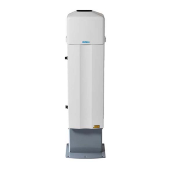
Ceilometer CL31 is able to detect three cloud layers simultaneously. If the cloud base is obscured due to precipitation or ground-based fog, CL31 reports Vertical Visibility. There is no need for adjustments in the field. The embedded software includes several service and maintenance functions and gives continuous status information from internal monitoring. - Page 20 USER'S GUIDE____________________________________________________________________ 0903-057 Figure 2 Vaisala Ceilometer CL31 The following numbers refer to Figure 2 above: 1 = Shield 2 = Measurement Unit 18 __________________________________________________________________ M210482EN-D...
-
Page 21: Product Nomenclature
For ship installations CLHUMITTER Internal Humidity Transmitter CL31USBCABLE USB maintenance cable The complete delivery also includes mating cables with connectors for power and communication, installation hardware, a key for the measurement unit door, and this CL31 User's Guide. VAISALA _______________________________________________________________________ 19... -
Page 22: Figure 3 Ceilometer Cl31 Measurement Unit Main Parts
USER'S GUIDE____________________________________________________________________ 0910-119 Figure 3 Ceilometer CL31 Measurement Unit Main Parts 20 __________________________________________________________________ M210482EN-D... - Page 23 8 = Ceilometer Engine Board CLE321 9 = Coaxial cable 226296 10 = Laser Monitor Board CLM311 11 = Battery Cage (for Battery 4592) 12 = AC Power CLP311 13 = Battery switch 14 = Window CLW311 15 = Measurement Unit Enclosure VAISALA _______________________________________________________________________ 21...
- Page 24 USER'S GUIDE____________________________________________________________________ This page intentionally left blank. 22 __________________________________________________________________ M210482EN-D...
-
Page 25: Chapter 3 Installation
When choosing an installation site it is recommended to use a wide open place where there are no tall trees, overhead lines, or antennas that could bend or move to the ceilometer measurement path. If the CL31 is to be installed in the proximity of radars or other powerful radio transmitters, it is recommended to position the measurement unit door away from such sources. -
Page 26: Figure 4 Foundation Construction
Figure 4 Foundation Construction There are two ways to create a concrete foundation for Ceilometer CL31; you can either use an existing concrete foundation or create a new one. If the tilt feature will be used (see section Using the Tilt Feature on page... -
Page 27: Creating A New Concrete Foundation
Tighten the foundation screws a few turns to attach the wedge bolts to the hole walls. Grounding CL31 is equipped with a separate grounding screw for external grounding at the bottom of the shield. At the installation site, a connection to a solid earth ground is mandatory CAUTION for adequate lightning and transient protection. -
Page 28: Unloading And Unpacking Instructions
USER'S GUIDE____________________________________________________________________ Unloading and Unpacking Instructions CL31 is shipped in one container that contains the shield, the measurement unit inside the shield, and all the equipment, accessories, and documentation needed for installation. Store the original packaging in case it is needed for transportation in the future. -
Page 29: Mounting Of Ceilometer Cl31
Chapter 3 _______________________________________________________________ Installation Mounting of Ceilometer CL31 Ceilometer CL31 is delivered with the measurement unit attached to the shield. The shield can be mounted with the measurement unit attached, but it is recommended that you first remove the measurement unit, mount the shield onto the foundation, and then install the measurement unit into the shield. -
Page 30: Figure 6 Removing And Attaching The Measurement Unit
USER'S GUIDE____________________________________________________________________ 0902-010 Figure 6 Removing and Attaching the Measurement Unit 28 __________________________________________________________________ M210482EN-D... -
Page 31: Figure 7 Mounting The Shield
Chapter 3 _______________________________________________________________ Installation SHIELD NUT M10 8 pcs WASHER B10 4 pcs FOUNDATION SCREW M10 4 pcs NORTH IN NORTHERN HEMISPHERE SOUTH IN SOUTHERN HEMISPHERE ) 0910-120 Figure 7 Mounting the Shield VAISALA _______________________________________________________________________ 29... -
Page 32: Using The Tilt Feature
USER'S GUIDE____________________________________________________________________ Using the Tilt Feature Ceilometer CL31 can operate in a tilted position. The built-in sensor detects the tilt angle, that is, the deviation from vertical. The tilt feature allows three tilt angles: vertical, 12 degrees with the measurement unit door upwards, and 12 degrees with the measurement unit door downwards. -
Page 33: Mounting The Optional Bird Deterrent
Mounting the Optional Bird Deterrent Ceilometer CL31 can be ordered with an optional bird deterrent; see Figure 9 on page 32. When installed, it prevents birds from landing on the ceilometer which could interfere with the measuring. -
Page 34: Figure 9 Ceilometer Cl31 Bird Deterrent
USER'S GUIDE____________________________________________________________________ 0910-115 Figure 9 Ceilometer CL31 Bird Deterrent Proceed as follows: Place the sideplates on both sides of the ceilometer top cover and attach them with two washers and screws. Slide a fluorocarbon line back and forth through the designated... -
Page 35: Startup
Assembling the Battery The no-break battery is delivered in the same container with the Ceilometer CL31, but it does not come attached to the measurement unit. To attach the no-break battery, you need a crosshead screwdriver and a 3 mm Allen-key. -
Page 36: Connecting The External Cables
USER'S GUIDE____________________________________________________________________ Close the battery cage lid and tighten the two screws to their places. Connect the no-break battery cable to the CLE321 board. Connecting the External Cables All external connectors are located at the bottom of the measurement unit. Figure 11 shows the external connectors J1, J2, J3, and J4. 0606-210 Figure 11 External Connectors (Bottom View) -
Page 37: Power Supply Connection
10 A. Data Line Connection Vaisala Ceilometer CL31 offers three possible options for the data line connection. These options are presented in Figure 12, Figure 13 and Figure 14 on the next pages. -
Page 38: Data Line Modem Connection
USER'S GUIDE____________________________________________________________________ Data Line Modem Connection 0902-006 Figure 12 Data Line Modem Connection Default Settings for the Data Line Modem Connection Modem mode V.22bis Answer Bit rate 2400 Data bits Stop bits Parity None 36 __________________________________________________________________ M210482EN-D... -
Page 39: Data Line Rs-485 Connection
"termination" as shown; this can improve data transmission speed, quality, and reliability. Default Settings for the Data Line RS-485 Connection Bit rate 19200 Data bits Stop bits Parity None VAISALA _______________________________________________________________________ 37... -
Page 40: Data Line Rs-232 Connection
Maintenance Terminal Connection Any terminal or PC with a serial interface and a terminal emulation program can be used for operating Ceilometer CL31. The maintenance terminal connection is established with the QMZ101 maintenance cable, which connects the RS-232 port of the PC to the maintenance port of the ceilometer. -
Page 41: Setting Up Maintenance Terminal Connection
None Operation of Maintenance Terminal Connection To operate the connection, do the following: Turn the power on in CL31. Open the CL31 maintenance with the open command. The prompt appears. For details, see Chapter 5, CEILO > Operation on page 55. -
Page 42: Figure 15 Ceilometer Engine Board Cle321
USER'S GUIDE____________________________________________________________________ 0910-103 Figure 15 Ceilometer Engine Board CLE321 The following numbers refer to Figure 15 above: 1 = Data line connection to AC Power CLP311 2 = Coaxial cable connection to Ceilometer Receiver CLR321 3 = Connection to Ceilometer Transmitter CLT321 4 = Connection to Battery 4592 5 = Connection to Ceilometer Receiver CLR321 6 = Connection to Laser Monitor Board CLM311... -
Page 43: Settings For Normal Operation
Optical adjustments have been made at the factory or depot, and there is no need to readjust them in the field. NOTE To switch the CL31 fully off, turn off the battery switch and the line power switch. Having the unit on with the battery supply will drain the battery. -
Page 44: Factory Settings Of User Programmable Parameters
Factory Settings of User Programmable Parameters Table 6 below lists the factory defaults of user-programmable parameters. The prevailing parameter settings of Ceilometer CL31 can be seen with the following command: get params parameter_group The user-programmable parameters can be changed with the following... -
Page 45: Functional Description
Theory of Operation Basic Operating Principle The operating principle of Ceilometer CL31 is based on the measurement of the time needed for a short pulse of light to traverse the atmosphere from the transmitter of the ceilometer to a backscattering cloud base and back to the receiver of the ceilometer. -
Page 46: Noise Cancellation
In its normal full-range operation, Ceilometer CL31 digitally samples the return signal from 0 to 50 µs. The sampling is repeated every 33 or 67 ns, providing a spatial resolution of 5 or 10 meters respectively from ground level up to 7 700 meters. -
Page 47: Return Signal Strength
000 ft. The height dependence is eliminated by multiplying the measured signal value with the square of height (height normalization). Noise, however, being height-independent from a measurement point of view, will then be correspondingly accentuated with increasing height. VAISALA _______________________________________________________________________ 45... -
Page 48: Backscatter Coefficient
USER'S GUIDE____________________________________________________________________ Backscatter Coefficient The volume backscatter coefficient, ß(z), represents the portion of light reflected back towards the ceilometer from a distance z (for example, from water droplets). A dense cloud gives a stronger reflection. This can be expressed as follows: ß(z) = k·σ... - Page 49 Ceilometer CL31 uses a contrast threshold value which, through many tests, has been found to give vertical visibility values closest to those reported by ground-based human observers. A safety margin is obtained...
-
Page 50: Sky Condition Algorithm
The sky condition algorithm is included in the 1.50 and latter software versions. You can activate the algorithm by entering an option code number to the ceilometer. The option code number is based on the CL31 ceilometer serial number. If the CL31 ceilometer is purchased with the sky condition activated, this has already been done at the factory. -
Page 51: Activation
This height gives the base height of a cloud or cloud layer represented by the cluster. The algorithm reports layers by combining clusters whose heights are close to each other and then selecting clusters that cover the greatest amount of sky. VAISALA _______________________________________________________________________ 49... -
Page 52: Figure 18 Basic Operation Of Cl31 Sky Condition Algorithm In A 2D Time-Height Domain
USER'S GUIDE____________________________________________________________________ 0911-075 Figure 18 Basic Operation of CL31 Sky Condition Algorithm in a 2D Time-Height Domain The sky condition algorithm reports the total sky cover in octas with values between 0 and 9. (One octa equals one eighth.) Value 9 is reported only in a vertical visibility condition. -
Page 53: Figure 19 Control Flow Of Sky Condition Algorithm
Vertical visibility measurements are also converted into cloud hits. After ceilometer measurements have been converted, the amount of clear sky, the amount covered by cloud VAISALA _______________________________________________________________________ 51... - Page 54 USER'S GUIDE____________________________________________________________________ hits and the amount covered by high clouds are determined for the unit. Total sky cover is adjusted using the value received from the Initialize module. The adjusted total sky cover gets the value of 8 only if no clear sky was detected and the measurements do not have any features that indicate there is no overcast condition.
- Page 55 Chapter 4 ______________________________________________________ Functional Description However, the cumulative cover of 8 octas is only reported if the layer is the highest layer and if the total sky cover from the Select module is 8 octas. VAISALA _______________________________________________________________________ 53...
- Page 56 USER'S GUIDE____________________________________________________________________ This page intentionally left blank. 54 __________________________________________________________________ M210482EN-D...
-
Page 57: Chapter 5 Operation
Operation Modes Serial Lines - Open and Closed Port As shown in Figure 11 on page 34, there are two line outputs in CL31, the maintenance line (external connector J4) and the data line (external connector J3). The data line is intended to be used for measurement data communication and can be operated through a modem or a serial line (RS-232 or RS-485). - Page 58 - OPEN: This is the user dialog state. In this state, the device responds to user commands and command input is echoed. A command prompt is displayed to indicate that CL31 is ready for command CEILO > input from the user. The commands are executed by pressing ENTER, for example, .
-
Page 59: User Commands
These advanced level commands are presented in Table 9 on page 60. The password for this level is "advanced". The commands on this level should only be used according to the instructions in this manual. VAISALA _______________________________________________________________________ 57... -
Page 60: Table 8 User Level Commands
USER'S GUIDE____________________________________________________________________ Table 8 User Level Commands Command Description close Closes a user interface. Releases a port for message transmission. get diag contamination Prints diagnostic history of window contamination. get diag angle Prints diagnostic history of inclinometer angle. get diag battery Prints diagnostic history of battery voltage. - Page 61 Sets Msg1 with 10x770 profile. set message type msg1_20x385 Sets Msg1 with 20x385 sample profile with 385 samples and 20 m resolution. set message type msg1_5x1500 Sets Msg1 with 5x1500 profile. set message type msg1_5x770 Sets Msg1 with 5x770 profile. VAISALA _______________________________________________________________________ 59...
-
Page 62: Table 9 Advanced Level Commands
USER'S GUIDE____________________________________________________________________ Command Description set message type msg1_base Sets Msg1 without a profile. set message type msg2_10x770 Sets Msg2 with 10x770 profile. set message type msg2_20x385 Sets Msg2 with 20x385 profile. set message type msg2_ 5x1500 Sets Msg2 with 5x1500 profile. set message type msg2_ 5x770 Sets Msg2 with 5x770 profile. - Page 63 Enables the humitter option. set option humitter off Disables the humitter option. set option sky_cond off Disables the sky condition option. set option sky_cond on 0 .. 99999 Enables the sky condition option with an activation code. VAISALA _______________________________________________________________________ 61...
-
Page 64: Data Messages
USER'S GUIDE____________________________________________________________________ Data Messages To ease the use of Ceilometer CL31 and to ease the transfer from old ceilometer versions to the new one, CL31 includes data messages used in CT12K, CT25K, CT25KAM, and LD40. CL31 provides the following data messages:... -
Page 65: Cl31 Data Messages No. 1 And 2
00000111112222233333 ... (5 x 770 bytes) 4th line 3852 char. 1a3f 5th line 8 char. Total 3956 char. An example of CL31 data message No. 2 is presented below: CLA10021 1st line 12 char. 30 01230 12340 23450 FEDCBA987654 2nd line 35 char. 3 055... -
Page 66: Table 11 Messages With 5 M Resolution (High Resolution)
USER'S GUIDE____________________________________________________________________ Table 11 Messages with 5 m Resolution (High Resolution) Message Message Name Length Min bps Data/Month Min bps Data/Month Number (bytes) (3 s) (3 s) (15 s) (15 s) Subclass msg1_5x1500 7606 28.8k 6267 MB 9600 1253 MB msg1_5x770 3956 14.4k... - Page 67 (8000 0000 0000) Transmitter shut-off (A) (4000 0000 0000) Transmitter failure (A) (2000 0000 0000) Receiver failure (A) (1000 0000 0000) Voltage failure (A) (0800 0000 0000) (Spare) (A) (0400 0000 0000) Memory error (A) VAISALA _______________________________________________________________________ 65...
- Page 68 USER'S GUIDE____________________________________________________________________ (0200 0000 0000) Light path obstruction (A) (0100 0000 0000) Receiver saturation (A) (0080 0000 0000) (spare) (A) (0040 0000 0000) (spare) (A) (0020 0000 0000) (spare) (A) (0010 0000 0000) (spare) (A) (0008 0000 0000) (spare) (A) (0004 0000 0000) (spare) (A) (0002 0000 0000) Coaxial cable failure (A) (0001 0000 0000) Ceilometer engine board failure (A)
- Page 69 = Cloud amount of the 5th layer in octas = Height of the 5th cloud layer The reporting resolution is 10 m or 100 ft depending on the units selection. If the cloud amount is zero, the corresponding layer height is ///. VAISALA _______________________________________________________________________ 67...
- Page 70 USER'S GUIDE____________________________________________________________________ 3RD LINE (4TH LINE IN MESSAGE NO. 2) Example: 00100 10 0770 098 +34 099 12 621 L0112HN15 139 where 00100 = Parameter SCALE, 100 (%) is normal (0 ... 99999 possible) = Backscatter profile resolution in meters. 0770 = Length of the profile in samples 385, 770, 1400, or 1500 = Laser pulse energy, % of nominal factory setting (0 ...
-
Page 71: Crc16 Checksum
The CRC16 checksum can be calculated using the following algorithm written in the C programming language: /* 16-bit type. */ typedef unsigned short Word16; /* Calculate CRC-16 value as used in CL31. */ Word16 crc16(const unsigned char *buf, int len) Word16 crc; Word16 xmask;... -
Page 72: Cl31 Status Message
USER'S GUIDE____________________________________________________________________ CL31 Status Message The Status message displays the internal monitoring of the entire unit. It is mainly meant for testing and maintenance purposes. The Status message can be displayed by giving the status command. An example of the status message is presented below: CL0100S0... - Page 73 13TH LINE Line 13 displays the power-save mode status and sleep interval settings of the CL31. In normal use, the power-save mode is disabled . If the power-save mode is on, the sleep interval indicates the interval when the CL31 does not measure.
- Page 74 21ST LINE Line 21 displays the window contamination status and outlaser settings of the CL31. The estimated transparency of 90 % to 100 % means that the window is clean. It is recommended that the window is cleaned whenever there is a window contamination warning, that is, the transparency is estimated as 70 % or lower.
-
Page 75: Ct12K Messages
= Carriage Return + Line Feed CT12K Messages Ceilometer CL31 also includes two Ceilometer CT12K messages. These are digital message No.2 and digital message No.3. CT12K Digital Message No. 2 This message contains detailed range gate data, and internal monitoring data for the most important variables. - Page 76 USER'S GUIDE____________________________________________________________________ An example of digital message No.2 is presented below: 10 04200 00150 ///// ///// 0000011010 2 0 0.08 36 0 100 23.9 0.00 0DD .......DD (data values;) ...
- Page 77 Sky is fully obscured but no cloud base can be detected from echo signal received (e.g. fog or precipitation) Sky is partially obscured and no cloud base is detected No CL31 alarm is active Alarm is active Space if S = 0 ‘bel’...
- Page 78 USER'S GUIDE____________________________________________________________________ 3RD LINE The second line of the message is status line 2. Example: G F N.NN SUM IIN LAS TLx OF.FS XX PP where Low gain High gain Always (Laser pulse frequency. N/A) N.NN Background radiance/100. One digit, two decimals. Sum of total backscattered power per unit solid angle, that is, range and instrument normalization applied.
-
Page 79: Ct12K Digital Message No. 3
2ND LINE The first line of the message is status line 1. Status line 1 of digital message No.3 is identical to that of message No. 2 (see section CT12K Digital Message No. 2 on page 73). VAISALA _______________________________________________________________________ 77... -
Page 80: Ct25K Data Messages
All other characters indicate a gate-by-gate combination of backscatter according to the binary nibble, converted to hexadecimal. CT25K Data Messages Ceilometer CL31 includes two Ceilometer CT25K data messages. These are data message No. 1 and data message No. 6. CT25K Data Message No. 1 This message is intended for cloud height/vertical visibility measurement when no other measurement information is desired. - Page 81 Example: 30 01230 12340 23450 FEDCBA98 Second line of CT25K data message No. 1 is identical to that of CL31 data message No. 1 (see section CL31 Data Messages No. 1 and 2 on page 63), except for the status bit string, which is 4-byte hex coded. The...
-
Page 82: Ct25K Data Message No. 6
USER'S GUIDE____________________________________________________________________ (0040 0000) Battery low (W) (0020 0000) Transmitter expire warning (W) (0010 0000) Heater or humidity sensor failure (W) (0008 0000) High radiance warning together with b02 (W) (0004 0000) Engine, receiver, or laser monitor failure warning (W) (0002 0000) Relative Humidity is high >... - Page 83 The eighth number of line: Height of the 4th cloud layer. The reporting resolution is 100 ft or 10 m depending on feet or meter selection. If the cloud amount is zero, the corresponding layer height is ///. VAISALA _______________________________________________________________________ 81...
-
Page 84: Ct25Kam Data Messages
=> 20.4 Kbytes/h, 490 Kbytes/d, 14.6 Mbytes/mo. at 4 msg/min, uncompressed LD40 Standard Telegram Ceilometer CL31 includes one Ceilometer LD40 data message. This is the standard telegram 'X1TA'. This message is given in clear text and includes cloud heights and additional meteorological data, date, time, sensor address, and status information of the instrument. - Page 85 System status and messages Checksum (This value is only an example; the correct value may be different from this one.) Carriage return + Line feed End-of-transmission character NOTE The notation '_' stands for a space character. VAISALA _______________________________________________________________________ 83...
-
Page 86: Telegram Structure Remarks
An alarm causes data telegrams to contain invalid data. A warning status does not cause invalid data. The following tables describe how CL31 is mapped to the LD40 error groups. See Table 12 on page 85 for the definition of the different error groups. -
Page 87: Table 12 Error Group Definition
Receiver saturation (A) Table 15 Error Group 3 (Byte 85) Error Code Description Receiver OK Not used Not used Not used Receiver failure (A) or Coaxial cable failure (A) or Receiver warning (W) Not used Not used VAISALA _______________________________________________________________________ 85... -
Page 88: Table 16 Error Group 4 (Byte 86)
USER'S GUIDE____________________________________________________________________ Table 16 Error Group 4 (Byte 86) Error Code Description Transmitter OK Transmitter expires (laser power low) (W) Transmitter failure Not used Not used Not used Transmitter shutoff (laser temperature too high) (A) Table 17 Error Group 5 (Byte 87) Error Code Description Status OK... -
Page 89: Checksum Calculation
2Com = Sum + 1= 0x037D + 0x01 = 0x0C83 HEX = 3203 DEZ . Take lower byte and build ASCII-character: The lower byte of 2Com is 0x83 HEX, so the high byte of the checksum is 8 and the low byte is 3: Checksum = 83 VAISALA _______________________________________________________________________ 87... -
Page 90: Manual Message
USER'S GUIDE____________________________________________________________________ Manual Message The ceilometer can be set to transmit user defined cloud heights and status information. User can set a cloud message in the format of line 2 of any real cloud message (for example, Message No. 1 or CT25K data message). -
Page 91: Polling Mode
NOTE Ceilometer CT12K messages cannot be polled. The CL31 unit can be assigned an identification of one-character digit or letter. The factory setting is 0 (zero). The polling mode is activated with the following command: set message transmission request CEILO >... -
Page 92: Table 20 Command Telegram Description 'Polling Request
If the id character in a polling string is replaced with a blank space, all ceilometers on the line will respond. Accordingly, if No is a blank space, CL31 sends the default message. In RS-485 mode id is always needed, the blank space is ignored. -
Page 93: Chapter 6 Maintenance
PC with a serial connection (see section CL31 Status Message on page 70). Proper function of the window blower, the only mechanically moving part, is automatically checked once an hour. -
Page 94: Cleaning
After 5 years of operation, calibrate the window contamination measurement. In addition, if the CL31 system starts issuing Window Contamination warnings frequently without a real reason, this may indicate that the window is worn out or the window contamination measurement has drifted. -
Page 95: Checking The Door Gasket
Replace the battery if signs of mechanical rupture are observed. Storage If the CL31 is stored unpacked for extended periods of time in an unconditioned area, keep caps on all external connectors. Keep the measurement unit door closed and also keep a dust cover on the window during long periods of storage. - Page 96 USER'S GUIDE____________________________________________________________________ This page intentionally left blank. 94 __________________________________________________________________ M210482EN-D...
-
Page 97: Chapter 7 Troubleshooting
- 226296 Coaxial cable - 4592 Battery If damage is suspected in a subassembly or a board, replace it with a spare part and send the defective part to Vaisala for repair/replacement. NOTE Replacements must only be performed by qualified maintenance personnel, and they must be done according to the instructions in Chapter 8, Repair, on page 103. -
Page 98: Accessing Diagnostic Information
Equipment for Troubleshooting To establish a service connection to the CL31 you need to have a maintenance terminal which can be a palmtop computer with an RS-232 Interface or a PC with serial interface, Maintenance cable QMZ101, and any terminal program. - Page 99 After this, place a piece of white paper on the ceilometer window. The blower should start within one minute. Remove the paper. The blower should stop within eight minutes. If there are clouds present, compare the ceilometer measurement with a qualified weather observer's height approximation. VAISALA _______________________________________________________________________ 97...
- Page 100 USER'S GUIDE____________________________________________________________________ In case there are no clouds present and if the site is suitable, do a hard target test. Turn the measurement unit 90 degrees and aim it on a fixed target (such as a wall or a forest front). The minimum distance to a hard target should be 300 meters (1 000 ft).
-
Page 101: Warning And Alarm Messages
(option) connected. disable the option in the software. Humidity sensor is damaged. Contact technical support and send the ceilometer CL31 to Service Center for the humidity sensor to be replaced. Heater fault warning Window blower circuit breaker is Check that the window blower circuit not ON. -
Page 102: Table 22 Cl31 Status, Alarms
Transmitter shut-off alarm Direct sunlight has heated the Wait for the sun to exit the field-of- (Laser temperature > 85 °C) laser. view. CL31 will return to normal operation. Environment temperature is too Check if there is a specific reason high. -
Page 103: Table 23 Cl31 Status, Miscellaneous Problems
Chapter 7 ___________________________________________________________ Troubleshooting Table 23 CL31 Status, Miscellaneous Problems Problem Reason Instructions CL31 does not start, no Power is not connected. Check that both the main and the LEDs are lit battery switches are in the ON position. Check the presence and correctness of the line voltage, and make sure that the battery is OK. -
Page 104: Technical Support
USER'S GUIDE____________________________________________________________________ Technical Support For technical questions, contact the Vaisala technical support: E-mail helpdesk@vaisala.com +358 9 8949 2790 Vaisala Service Centers 102 _________________________________________________________________ M210482EN-D... -
Page 105: Chapter 8 Repair
Power cable (230V) DMX501SP Modem Module 226296SP Coaxial Cable TERMBOX-1200SP Termination Box with overvoltage protection CLTERMBOXSP Termination Box QMZ101SP Terminal Cable for MAWS CL31USBCABLESP CL31USB Cable CLRADIOKITSP Radio Modem Kit CL31BIRDKITSP Bird deterrent CL31TOPCOVERKIT Top Cover Kit VAISALA ______________________________________________________________________ 103... -
Page 106: Figure 22 Cl31 Maintenance Parts
USER'S GUIDE____________________________________________________________________ 0910-102 Figure 22 CL31 Maintenance Parts 104 _________________________________________________________________ M210482EN-D... -
Page 107: Replacing Window Clw311
16 = Battery cable Replacing Window CLW311 Refer to number 13 in Figure 22 on page 104. Vaisala recommends that Ceilometer Window CLW311 is replaced NOTE indoors to prevent water and other contamination from getting into the measurement unit. To replace Ceilometer Window CLW311, you will need a 2.5 mm Allen- key and a screwdriver. -
Page 108: Figure 23 Window Clw311
USER'S GUIDE____________________________________________________________________ 28), disconnect the blower cable from connector J1 (see Figure 11 on page 34) and pull out the unit. Loosen the 12 screws on the frame of the window and remove the window by lifting it out with the screws attached. Also remove any pieces of the old gasket. -
Page 109: Replacing Ceilometer Laser Transmitter Clt321
Ceilometer Transmitter from its normal position without first switching off both the line and the battery power and detaching the transmitter ribbon cable from the Ceilometer Engine Board CLE321. CAUTION Servicing the equipment must only be performed by qualified maintenance personnel. VAISALA ______________________________________________________________________ 107... -
Page 110: Figure 24 Laser Transmitter Clt321
USER'S GUIDE____________________________________________________________________ 0910-112 Figure 24 Laser Transmitter CLT321 The transmitter should be replaced if the ceilometer unit has been generating warnings and alarms, and a malfunction with the operation of the transmitter has been detected. To replace Ceilometer Laser Transmitter CLT321, you will need a 2.5 mm Allen-key. -
Page 111: Replacing Ceilometer Receiver Clr321
Then proceed as follows: Open the measurement unit door and confirm that there is an active receiver failure. In case of a receiver failure, the CLR ok LED will be off. Refer to Figure 26 on page 111. VAISALA ______________________________________________________________________ 109... - Page 112 USER'S GUIDE____________________________________________________________________ Switch off the power with all three switches (F1, F2, and Battery). For the location of the switches, see Figure 15 on page 40 and Figure 16 on page 41. WARNING Disconnect the power cable from connector J2 before continuing. Detach the coaxial cable (refer to number 3 in Figure 22 on page 104) from the receiver.
-
Page 113: Replacing Ceilometer Engine Board Cle321
Ceilometer Engine Board CLE321 should be replaced if the ceilometer unit has been generating warnings and alarms, and a malfunction with the operation of the CLE321 board has been detected. To replace Ceilometer Engine Board CLE321, you will need a screwdriver. VAISALA ______________________________________________________________________ 111... - Page 114 USER'S GUIDE____________________________________________________________________ Then proceed as follows: Open the measurement unit door and confirm that there is an active CLE321 board failure. In case of a CLE321 board failure, the CLE ok LED will be off. Refer to Figure 26 on page 111. Switch off the power with all three switches (F1, F2, and Battery).
-
Page 115: Replacing No-Break Battery 4592
Figure 15 on page 40 and Figure 16 on page 41. WARNING Disconnect the power cable from connector J2 before continuing. Disconnect the battery cable (refer to number 16 in Figure 22 on page 104) from the CLE321 board. VAISALA ______________________________________________________________________ 113... -
Page 116: Replacing Ac Power Clp311
USER'S GUIDE____________________________________________________________________ Remove the two screws locking the lid of the battery cage. One of the screws is located on top of the battery cage, the other is on the left side near the top of the cage. Open the lid of the battery cage and slide out the battery. Disconnect the battery cable. -
Page 117: Figure 28 Ac Power Clp311
Allen screws on its front cover. Detach the internal heater connector and holding the cable aside, carefully pull out the Optics Unit upper end first. NOTE Do not touch the lens of the Optics Unit. VAISALA ______________________________________________________________________ 115... - Page 118 USER'S GUIDE____________________________________________________________________ Detach the CLM311 twisted pair cable (refer to number 15 in Figure 22) from the CLE321 board. Remove the battery. Refer to steps 3 to 5 in section Replacing No- break Battery 4592 on page 113. Remove the battery cage by removing the three screws holding it in its place.
-
Page 119: Replacing Window Blower Clb311
Switch off the power with all three switches (F1, F2, and Battery). For the location of the switches, see Figure 15 on page 40 and Figure 16 on page 41. WARNING Disconnect the power cable from connector J2 before continuing. VAISALA ______________________________________________________________________ 117... -
Page 120: Replacing Internal Heater Clh311
USER'S GUIDE____________________________________________________________________ 0910-105 Figure 29 Window Blower CLB311-115 / CLB311-230 As the blower is attached to the shield of the ceilometer, you will first have to remove the measurement unit from the shield to get to the blower. To remove the measurement unit, loosen the three attachment screws (marked A in Figure 6 on page 28), disconnect the blower cable from connector J1 (see Figure 11 on page 34) and pull out the unit. -
Page 121: Figure 30 Internal Heater Clh311-115 / Clh311-230
Switch off the power with all three switches (F1, F2, and battery). For the location of the switches, see Figure 15 on page 40 and Figure 16 on page 41. WARNING Disconnect the power cable from connector J2 before continuing. VAISALA ______________________________________________________________________ 119... - Page 122 USER'S GUIDE____________________________________________________________________ Close the enclosure door and remove the measurement unit. To do this, loosen the three attachment screws (marked A in Figure 6 on page 28, disconnect the blower cable from connector J1 (see Figure 11 on page 34) and pull out the unit. Remove the metal plate protecting the heater by loosening its two screws.
-
Page 123: Replacing Laser Monitor Board Clm311
Open the measurement unit door and switch off the power with all three switches (F1, F2, and battery). For the location of the switches, see Figure 15 on page 40 and Figure 16 on page 41. WARNING Disconnect the power cable from connector J2 before continuing. VAISALA ______________________________________________________________________ 121... - Page 124 Place all heater cables behind the holder and tighten the four holder screws. Reconnect the battery, transmitter, receiver, and data cables to the CLE321 board. Connect the power cable to connector J2 and the maintenance terminal to CL31. 122 _________________________________________________________________ M210482EN-D...
-
Page 125: Replacing Modem Module Dmx501 (Optional)
If other failures exist, separate troubleshooting may be necessary. Replacing Modem Module DMX501 (Optional) CAUTION Servicing the equipment must only be performed by qualified maintenance personnel. Always replace the modem module indoors. VAISALA ______________________________________________________________________ 123... -
Page 126: Figure 32 Modem Module Dmx501
USER'S GUIDE____________________________________________________________________ 0910-108 Figure 32 Modem Module DMX501 To replace Modem Module DMX501, you will need a screwdriver. As the DMX501 module is located inside the CLE321 module, you will have to remove the CLE321 board to get to the DMX501 module. Proceed as follows: Open the front door of the ceilometer enclosure and switch off the power with all three switches (F1, F2, and battery). -
Page 127: Figure 33 Dmx501
Reattach the receiver ribbon cable, the transmitter ribbon cable, and the coaxial cable when the board is pushed halfway in. Push the CLE321 board in such a way that it connects to the back plane connector. Tighten the hand screws to lock the board position. VAISALA ______________________________________________________________________ 125... - Page 128 USER'S GUIDE____________________________________________________________________ Connect the data line connector to the same position as it was connected to on the previous board. Connect the power cable to connector J2. Switch on the power with all three switches. Wait until the Laser on LED starts blinking at 2-second intervals. Make sure that all six diagnostic LEDs light up after the self-test.
-
Page 129: Chapter 9 Technical Data
Chapter 9 ____________________________________________________________ Technical Data CHAPTER 9 TECHNICAL DATA This chapter provides the technical data of the product. Specifications This section describes the different technical specifications of Vaisala Ceilometer CL31. Mechanical Specifications Table 25 Ceilometer CL31 Mechanical Specifications Property Description / Value... -
Page 130: External Connector J2 - Power Input
USER'S GUIDE____________________________________________________________________ External Connector J2 - Power Input Table 27 Power Input Property Description / Value At nominal line voltage 100V or 115 V or 230 V Power consumption (typical): Total 310 W Measurement unit 15 W Internal heater 100 W Window conditioner heater 175 W Window blower... -
Page 131: External Connector J4 - Maintenance Line
36, Figure 13 on page 37, and Figure 14 on page 38. External Connector J4 - Maintenance Line Maintenance line is intended for on-site maintenance and can be used with a Ceilometer Maintenance Terminal, PC, or other terminal. VAISALA ______________________________________________________________________ 129... -
Page 132: Figure 34 Pin Connections Of Connector J4
USER'S GUIDE____________________________________________________________________ Table 29 Maintenance Line Property Description / Value Connector (J4) Female five (5) pin M12 connector (e.g. Lumberg RKF 5 / 0,5 M) Mating connector type Male five (5) pin M12 connector (e.g. Lumberg RST 5-644) Baud rate 9600 default and standard 300, 2400, 4800, 9600, 19200, 38400, 57600, 115 200 bps available... -
Page 133: Modem Module Dmx501
Silicon Avalanche Photodiode (APD) Surface diameter 0.5 mm (0.02 in.) Receiver bandwidth 3 MHz (-3db) Interference filter Center wavelength 915 nm typical 50 % pass band 36 nm Transmissivity at 913 nm 80 % typical Field-of-view divergence ± 0.83 mrad VAISALA ______________________________________________________________________ 131... -
Page 134: Optical System Specifications
USER'S GUIDE____________________________________________________________________ Optical System Specifications Table 33 Optical System Specifications Property Description / Value Optics System Focal Length 300 mm (11.8 in.) Effective lens diameter 96 mm (3.8 in.) Lens transmittance 96 % typical Window transmittance 97 % typical, clean Performance Specifications Table 34 Performance Specifications... -
Page 135: Bird Deterrent Installation
Appendix A ___________________________________________________ Bird Deterrent Installation APPENDIX A BIRD DETERRENT INSTALLATION 0910-116 Figure 35 CL31 Bird Deterrent Installation VAISALA ______________________________________________________________________ 133... -
Page 136: Figure 36 Bird Deterrent In Detail
USER'S GUIDE____________________________________________________________________ 0910-114 Figure 36 Bird Deterrent in Detail 134 _________________________________________________________________ M210482EN-D... -
Page 137: Figure 37 Blood Knot Instructions
Appendix A ___________________________________________________ Bird Deterrent Installation 0910-117 Figure 37 Blood Knot Instructions VAISALA ______________________________________________________________________ 135... - Page 138 USER'S GUIDE____________________________________________________________________ This page intentionally left blank. 136 _________________________________________________________________ M210482EN-D...
-
Page 139: Index
Letter case in commands CL-VIEW LIDAR Contrast threshold Lidar equation Lidar ratio Data messages CL31 Status message Main parts CT25K data message No. 1 Maintenance CT25K data message No. 6 Alarms and warnings CT25KAM data message No. 60 Battery check CT25KAM data message No. - Page 140 USER'S GUIDE____________________________________________________________________ Activation Option code No-break power supply STATUS command Noise cancellation Storage Switch settings for normal operation OPEN command Operating principle Operation modes Termination box CONTINUOUS Transmitter STANDBY Transportation Optical filter Troubleshooting Optical system Alarms Optical termination hood 19, 96 Miscellaneous problems Optional parts Warnings...
- Page 142 *M210482EN*...
Need help?
Do you have a question about the CL31 and is the answer not in the manual?
Questions and answers