Table of Contents
Advertisement
Quick Links
Download this manual
See also:
User Manual
Advertisement
Table of Contents
Troubleshooting

Related Manuals for Vaisala CL31


Summary of Contents for Vaisala CL31
- Page 1 Vaisala Ceilometer CL31 UIDE M210482EN-B October 2004...
- Page 2 The contents are subject to change without prior notice. Please observe that this manual does not create any legally binding obligations for Vaisala towards the customer or end user. All legally binding commitments and agreements are included exclusively in the applicable supply contract or...
-
Page 3: Table Of Contents
Laser Safety ................ 10 ESD Protection..............11 Recycling ................12 Warranty.................. 12 CHAPTER 2 PRODUCT OVERVIEW................13 Introduction to Vaisala Ceilometer CL31 ......13 Product Nomenclature............15 CHAPTER 3 INSTALLATION.................... 19 Installation Procedure............19 Unloading and Unpacking Instructions ....... 19 Preparing a Concrete Foundation........ - Page 4 User's Guide ______________________________________________________________________ User Commands ..............39 Data Messages................44 CL31 Data Messages No. 1 and 2 ........45 CRC16 Checksum............51 CL31 Status Message ............52 CT12K Messages ..............55 CT12K Digital Message No. 2........55 CT12K Digital Message No. 3........59 CT25K Data Messages ............60 CT25K Data Message No. 1 ..........60 CT25K Data Message No.
- Page 5 Environmental Conditions Specifications......123 INDEX ......................125 List of Figures Figure 1 Vaisala Ceilometer CL31............14 Figure 2 Ceilometer CL31 Main Parts ............ 16 Figure 3 Measurement Unit Handle ............20 Figure 4 Foundation Construction ............21 Figure 5 Removing and Attaching the Measurement Unit ..... 23 Figure 6 Mounting the Shield..............
- Page 6 User's Guide ______________________________________________________________________ Figure 17 CL31 ..................96 Figure 18 Main Components of Ceilometer CL31 ........98 Figure 19 Ceilometer Engine Board CLE311 ...........99 Figure 20 Grounding Wires of the Internal Cable Set (top view) ....110 Figure 21 Internal Heater Wiring and Connector at the Left of the Optics Frame ..................111...
-
Page 7: Chapter 1 General Information
- Chapter 7, Troubleshooting, describes common problems, their probable causes and remedies, and gives the contact information. - Chapter 8, Repair, explains how to remove and replace different parts of Vaisala Ceilometer CL31. VAISALA ________________________________________________________________________ 7... -
Page 8: Related Manuals
M210310EN-A Termination Box User's Guide Feedback Vaisala Customer Documentation Team welcomes your comments and suggestions on the quality and usefulness of this publication. If you find errors or have other suggestions for improvement, please indicate the chapter, section, and page number. You can send comments to us by e-mail: manuals@vaisala.com... -
Page 9: Product Related Safety Precautions
Product Related Safety Precautions Vaisala Ceilometer CL31 delivered to you has been tested for safety and approved as shipped from the factory. The following safety precautions must be observed during all phases of operation, service,... -
Page 10: Laser Safety
Internal Heater CLH311 can be hot and is equipped with the following warning labels: Laser Safety Vaisala Ceilometer CL31 is classified as a Class 1M laser device in accordance with International Standard IEC/EN 60 825-1. Complies with 21 CFR 1040.10 and 1040.11 except for the deviations pursuant to the Laser Notice No. -
Page 11: Esd Protection
Chapter 1 ________________________________________________________ General Information The device is equipped with the following label: Ceilometer CL31 is intended for operation in an area restricted from public access, and to be pointed vertically or near-vertically. The following precautions must be followed during the service and... -
Page 12: Recycling
Do not dispose of with regular household refuse. Warranty For certain products Vaisala normally gives a limited one-year warranty. Please observe that any such warranty may not be valid in case of damage due to normal wear and tear, exceptional operating conditions, negligent handling or installation, or unauthorized modifications. -
Page 13: Chapter 2 Product Overview
The software is designed to give the full backscatter profile. To make Ceilometer CL31 easier to use and to ease the transfer from old ceilometer versions to this new one, CL31 includes data messages used in CT12K, CT25K, CT25KAM, and LD40. -
Page 14: Figure 1 Vaisala Ceilometer Cl31
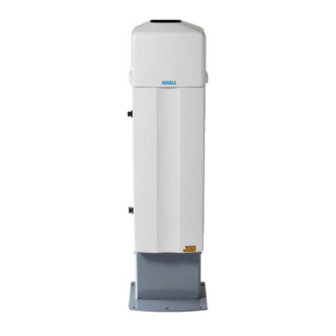
User's Guide ______________________________________________________________________ 0406-052 Figure 1 Vaisala Ceilometer CL31 The following numbers refer to Figure 1 above: Shield Measurement Unit 14 __________________________________________________________________ M210482EN-B... -
Page 15: Product Nomenclature
Shock Absorber For ship installations HMP50 UAB1A1A Internal Humidity Transmitter The complete delivery also includes mating cables with connectors for power and communication, installation hardware, a key for the measurement unit door, and this CL31 User's Guide. VAISALA _______________________________________________________________________ 15... -
Page 16: Figure 2 Ceilometer Cl31 Main Parts
User's Guide ______________________________________________________________________ 0311-057 Figure 2 Ceilometer CL31 Main Parts 16 __________________________________________________________________ M210482EN-B... - Page 17 Receiver ring Transmitter ring Ceilometer Transmitter CLT311 F1 Main circuit breaker F2 Window blower circuit breaker Ceilometer Engine Board CLE311 Laser Monitor Board CLM311 10 = Battery 4592 11 = AC Power CLP311 12 = Battery switch VAISALA _______________________________________________________________________ 17...
- Page 18 User's Guide ______________________________________________________________________ This page intentionally left blank. 18 __________________________________________________________________ M210482EN-B...
-
Page 19: Chapter 3 Installation
CL31. Unloading and Unpacking Instructions CL31 is shipped in one container that contains the shield, the measurement unit inside the shield, and all the equipment, accessories, and documentation needed for carrying out the installation. Store the original packaging for possible later transport need. -
Page 20: Preparing A Concrete Foundation
Vaisala office or authorized Depot for inspection. Preparing a Concrete Foundation The standard foundation for the CL31 ground installation is a concrete foundation. The minimum dimensions suggested are presented in Figure 4 on page 21. Mounting hardware is included with the delivery. -
Page 21: Figure 4 Foundation Construction
Chapter 3 _______________________________________________________________ Installation NOTE In case CL31 is used to replace another ceilometer (CT25K, CT12K, LD40, LD25, or LD12) the existing foundation and foundation screws can be used. 9412-027 Figure 4 Foundation Construction VAISALA _______________________________________________________________________ 21... -
Page 22: Mounting The Ceilometer Cl31
User's Guide ______________________________________________________________________ There are two alternative ways to create a concrete foundation for Ceilometer CL31. You can either cast a new concrete foundation or use an existing one. NOTE If the tilt feature will be used (see section Using the Tilt Feature on page 29), observe this in the layout of the foundation screws and shield placement. -
Page 23: Figure 5 Removing And Attaching The Measurement Unit
Chapter 3 _______________________________________________________________ Installation To mount Ceilometer CL31, proceed as follows: Remove the measurement unit from the shield. To do this, loosen the three attachment screws (marked A in Figure 5 below), disconnect the blower cable from connector J1 (see Figure 7 on page 25), and pull out the unit. -
Page 24: Figure 6 Mounting The Shield
User's Guide ______________________________________________________________________ 0311-056 Figure 6 Mounting the Shield 24 __________________________________________________________________ M210482EN-B... -
Page 25: Connecting The External Cables
J4 when it is not used. External mating connectors with 2 m (7 ft) cable are included for J2 and for J3. The power plug of the J2 cable can be cut when the unit is permanently installed at the final site. VAISALA _______________________________________________________________________ 25... -
Page 26: Data Line Connection
When the permanent line power installation is made, the maximum size of the fuse protecting the power line is 10 A. Data Line Connection Vaisala Ceilometer CL31 offers three possible options for the data line connection. These options are presented in the following figures. 0311-060... -
Page 27: Figure 9 Data Line Rs-485 Connection
Default Settings for the Data Line Modem Connection Modem mode V.22bis Bit rate 2400 Data bits Stop bits Parity None 0311-061 Figure 9 Data Line RS-485 Connection Default Settings for the Data Line RS-485 Connection Bit rate 19200 Data bits Stop bits Parity None VAISALA _______________________________________________________________________ 27... -
Page 28: Grounding
Grounding The power supply connector J2 provides a standard protective ground for the instrument chassis. CL31 is equipped with a separate grounding screw for external grounding at the bottom of the shield. CAUTION Connection to a solid earth ground at the installation site is mandatory for adequate lightning and transient protection. -
Page 29: Maintenance Terminal Connection
Functional Description, on page 73. Using the Tilt Feature Ceilometer CL31 is designed to allow operation in a tilted direction. The built-in tilt angle sensor detects the tilt angle, that is, the deviation from vertical. The tilt feature allows three tilt angles: vertical, 12 degrees with the measurement unit door upwards, and 12 degrees with the measurement unit door downwards. -
Page 30: Mobile Operation Aspects
NOTE For switching the CL31 power fully off, also turn off the battery switch in addition to the line power switch. Having the unit on with the battery supply will only drain the battery. -
Page 31: Startup
LEDs and switches, refer to Figure 12 on page 33 and Figure 13 on page 34. NOTE For switching the CL31 power fully off, also turn off the battery switch in addition to the line power switch. Having the unit on with the battery supply will drain the battery. -
Page 32: Figure 11 Subassembly Interconnections
User's Guide ______________________________________________________________________ 0311-058 Figure 11 Subassembly Interconnections 32 __________________________________________________________________ M210482EN-B... -
Page 33: Figure 12 Cl31 Switches
Connection to Laser monitor board CLM311 Connection to AC power CLP311 Connection to Internal heater CLH311 Battery switch 0406-053 Figure 12 CL31 Switches The following numbers refer to Figure 12 above: F1 Main circuit breaker F2 Heater/Blower circuit breaker VAISALA _______________________________________________________________________ 33... -
Page 34: Settings For Normal Operation
User's Guide ______________________________________________________________________ 0311-059 Figure 13 Ceilometer Engine Board CLE311 Settings for Normal Operation The switch settings for normal operation are as follows: Main circuit breaker F1 Heater/Blower circuit breaker F2 Battery switch The data message and interface configuration and the configuration of measuring interval and transmission speed are standard factory settings. -
Page 35: Factory Settings Of User Programmable Parameters
Factory Settings of User Programmable Parameters Table 4 below lists the factory defaults of user-programmable parameters. The prevailing parameter settings of Ceilometer CL31 can be seen with the following command: get params parameter_group The user-programmable parameters can be changed with the... - Page 36 User's Guide ______________________________________________________________________ This page intentionally left blank. 36 __________________________________________________________________ M210482EN-B...
-
Page 37: Chapter 4 Operation
The maintenance line is intended for on-site maintenance access, and is used only as a baseband. However, functionally the operation of the lines is identical, VAISALA _______________________________________________________________________ 37... - Page 38 - OPEN: This is the user dialog state. In this state, the user commands are responded to and command input is echoed. A command prompt is displayed to indicate that CL31 is CEILO > ready for command input from the user. The commands are executed by pressing ENTER, for example, .
-
Page 39: User Commands
These advanced level commands are presented in a separate table (see Table 6 on page 43). The password for this level is "advanced". The commands on this level should only be used according to the instructions in this manual. VAISALA _______________________________________________________________________ 39... -
Page 40: Table 5 User Level Commands
User's Guide ______________________________________________________________________ Table 5 User Level Commands Command Description close Closes a user interface. Releases a port for message transmission. get diag contamination Prints diagnostic history of window contamination. get diag angle Prints diagnostic history of inclinometer angle. get diag battery Prints diagnostic history of battery voltage. - Page 41 Maintenance serial port speed. set maint_port parity 7E1 Maintenance serial port settings. set maint_port parity 7O1 Maintenance serial port settings. set maint_port parity 8N1 Maintenance serial port settings. set message transmission delay Sets request-based delivery response delay (ms). VAISALA _______________________________________________________________________ 41...
- Page 42 User's Guide ______________________________________________________________________ Command Description set message transmission periodic Sets periodic message transmission. set message transmission request Sets message request-based delivery. set message interval 2 ... 120 Sets message delivery interval in seconds. set message port data Delivers messages into data port. set message port maintenance Delivers messages into maintenance port.
-
Page 43: Table 6 Advanced Level Commands
<string> Sets a manual message. Empty string disables. set message profile scale Scaling factor for range gate data (%). set message profile noise_h2 on Range gates data is always range normalized, even noise. VAISALA _______________________________________________________________________ 43... -
Page 44: Data Messages
Enables the sky condition option with an activation code. Data Messages To ease the use of Ceilometer CL31 and to ease the transfer from old ceilometer versions to the new one, CL31 includes data messages used in CT12K, CT25K, CT25KAM, and LD40. CL31 provides the... -
Page 45: Cl31 Data Messages No. 1 And 2
00000111112222233333 ... (5 x 770 bytes)↵ 4th line 3852 char. 1a3f♦↵ 5th line 8 char. Total 3956 char. An example of CL31 data message No. 2 is presented below: CLA10021☺↵ 1st line 12 char. 30 01230 12340 23450 FEDCBA987654↵ 2nd line 35 char. 3 055... -
Page 46: Table 7 Messages With 10 M Resolution (Standard Mode)
User's Guide ______________________________________________________________________ For data lines with low bandwidth, there is a short version of each message. In the short version of message No.1, lines 3 and 4 are left out. Correspondingly, in the short version of message No.2, lines 4 and 5 are left out. - Page 47 If detection status is 4: Highest signal detected If detection status is 0, 1, or 5: ///// 23450 = If detection status is 3: Highest cloud base height If detection status is 0, 1, 2, 4, ///// VAISALA _______________________________________________________________________ 47...
- Page 48 User's Guide ______________________________________________________________________ FEDC = Alarm (A), Warning (W), and internal status (S) information. Each character is BA98 a hexadecimal representation of four bits, i.e. values between 0 and 9 are 7654 presented with respective numbers and values 10, 11, 12, 13, 14, and 15 are presented with letters A, B, C, D, E, and F, respectively.
- Page 49 Cloud amount of the 4th layer in oktas = Eighth digit of line: Height of the 4th cloud layer = Ninth digit of line: Cloud amount of the 5th layer in oktas = Tenth number of line: Height of the 5th cloud layer VAISALA _______________________________________________________________________ 49...
- Page 50 User's Guide ______________________________________________________________________ The reporting resolution is 10 m or 100 ft depending on the selection. If the cloud amount is zero, the corresponding layer height is ///. 3RD LINE (4TH LINE OF MESSAGE NO. 2) Example: 00100 10 0770 098 +34 099 12 621 L0112HN15 139↵...
-
Page 51: Crc16 Checksum
The CRC16 checksum can be calculated using the following algorithm written in the C programming language: /* 16-bit type. */ typedef unsigned short Word16; /* Calculate CRC-16 value as used in CL31. */ Word16 crc16(const unsigned char *buf, int len) Word16 crc; Word16 xmask;... -
Page 52: Cl31 Status Message
End-of-Text character, that is, the first character included is C and the last one included is End-of-Text. CL31 Status Message The Status message displays the internal monitoring of the entire unit. It is mainly meant for testing and maintenance purposes. The Status message can be displayed by giving the status command. - Page 53 Message interpretation: 1ST LINE The first line of the CL31 status message is structurally identical to the first line of the CL31 data message No. 1 (see the message interpretation in section CL31 Data Messages No. 1 on page 45) except that the second to last character that identifies the message number, is always SØ☺↵.
- Page 54 17TH LINE Line 17 displays the window contamination status and outlaser settings of CL31. The estimated transparency of 90 % to 100 % means that the window is clean. It is recommended that the window is cleaned whenever there is a window contamination warning, that is, the transparency is estimated as 70 % or lower.
-
Page 55: Ct12K Messages
= Carriage Return + Line Feed ↵ CT12K Messages Ceilometer CL31 also includes two Ceilometer CT12K messages. These are digital message No.2 and digital message No.3. CT12K Digital Message No. 2 This message contains detailed range gate data, and internal monitoring data for the most important variables. - Page 56 User's Guide ______________________________________________________________________ An example of digital message No.2 is presented below: ↵ 10 04200 00150 ///// ///// 0000011010 ↵ ↵ 2 0 0.08 36 0 100 23.9 0.00 ↵ 0DD .......DD ↵ ↵ ↵ ↵ ↵ ↵ (data values;) ↵...
- Page 57 Sky is fully obscured but no cloud base can be detected from echo signal received (e.g. fog or precipitation) Sky is partially obscured and no cloud base is detected No CL31 alarm is active Alarm is active Space if S = 0 ‘bel’...
- Page 58 User's Guide ______________________________________________________________________ 3RD LINE The second line of the message is status line 2. Example: G F N.NN SUM IIN LAS TLx OF.FS XX PP↵ where Low gain High gain Always (Laser pulse frequency. N/A) N.NN Background radiance/100. One digit, two decimals. Sum of total backscattered power per unit solid angle i.e.
-
Page 59: Ct12K Digital Message No. 3
The first line of the message is status line 1. Status line 1 of digital message No.3 is identical to that of message No. 2 (see the message interpretation in section CT12K Digital Message No. 2 on page 55). VAISALA _______________________________________________________________________ 59... -
Page 60: Ct25K Data Messages
All other characters indicate a gate-by-gate combination of backscatter according to the binary nibble, converted to hexadecimal. CT25K Data Messages Ceilometer CL31 also includes two Ceilometer CT25K data messages. These are data message No. 1 and data message No. 6. CT25K Data Message No. 1 This message is intended for cloud height/vertical visibility measurement when no other measurement information is desired. - Page 61 Example: 30 01230 12340 23450 FEDCBA98↵ Second line of CT25K data message No. 1 is identical to that of CL31 data message No. 1 (see the message interpretation in section CL31 Data Messages No. 1 on page 45), except for the status bit string, which is 4-byte hex coded.
-
Page 62: Ct25K Data Message No. 6
User's Guide ______________________________________________________________________ (0080 0000) Window contaminated (W) (0040 0000) Battery low (W) (0020 0000) Transmitter expire warning (W) (0010 0000) Heater or humidity sensor failure (W) (0008 0000) High radiance warning together with b02 (W) (0004 0000) Engine, receiver, or laser monitor failure warning (0002 0000) Relative Humidity is high >... - Page 63 The eighth number of line: Height of the 4th cloud layer. The reporting resolution is 100 ft or 10 m depending on feet or meter selection. If the cloud amount is zero, the corresponding layer height is ///. VAISALA _______________________________________________________________________ 63...
-
Page 64: Ct25Kam Data Messages
=> 20.4 Kbytes/h, 490 Kbytes/d, 14.6 Mbytes/mo. at 4 msg/min, uncompressed LD40 Standard Telegram Ceilometer CL31 also includes one Ceilometer LD40 data message. This is the standard telegram 'X1TA'. This message is given in clear text and includes cloud heights and additional meteorological data, date, time, sensor address, and status information of the instrument. - Page 65 = Checksum (This value is only an example; the correct value may be different from this one.) = Carriage return + Line feed ↵ = End-of-transmission character ♦ NOTE The notation '_' stands for a space character. VAISALA _______________________________________________________________________ 65...
-
Page 66: Telegram Structure Remarks
An alarm will lead to data telegrams to contain invalid data. A warning status does not cause invalid data. The following tables describe how CL31 is mapped to the LD40 error groups. Table 9 below shows the definition of the different error groups. -
Page 67: Table 9 Error Group Definition
Receiver saturation (A) Table 12 Error Group 3 (Byte 85) Error Code Description Receiver OK Not used Not used Not used Receiver failure (A) or Coaxial cable failure (A) or Receiver warning (W) Not used Not used VAISALA _______________________________________________________________________ 67... -
Page 68: Table 13 Error Group 4 (Byte 86)
User's Guide ______________________________________________________________________ Table 13 Error Group 4 (Byte 86) Error Code Description Transmitter OK Transmitter expires (laser power low) (W) Transmitter failure Not used Not used Not used Transmitter shutoff (laser temperature too high) (A) Table 14 Error Group 5 (Byte 87) Error Code Description Status OK... -
Page 69: Checksum Calculation
2Com = ¬ Sum + 1= ¬ 0x037D + 0x01 = 0x0C83 HEX = 3203 DEZ . Take lower byte and build ASCII-character: The lower byte of 2Com is 0x83 HEX, so the high byte of the checksum is 8 and the low byte is 3: Checksum = 83 VAISALA _______________________________________________________________________ 69... -
Page 70: Manual Message
The polling string can contain the message identification. The CL31 unit can be assigned an identification of one-character digit or letter. The factory setting is 0 (zero). The polling mode is activated with the following command: set message transmission request CEILO >... -
Page 71: Table 17 Command Telegram Description 'Polling Request
<Enq> CLIdNo ↵ where Character ENQUIRE = ASCII 05H = control-E. Fixed ceilometer identifier; CL for CL31 messages, CT for CT25K and CT25KAM messages. Identification character, 7-bit printable ASCII character. Optional message identifier; 1 or 6 for CT messages and 1 or S for CL messages. - Page 72 User's Guide ______________________________________________________________________ Byte Example Description this case --> 1 7-17 P---------- Command indicator --> P (polling), byte 8-17 not used and filled with '-' 18-19 Checksum (Hex-coded two's complement of the sum of bytes from 0 to 20, excluding bytes 18 and 19. <EOT>...
-
Page 73: Functional Description
Theory of Operation Basic Principle of Operation The operating principle of Ceilometer CL31 is based on the measurement of the time needed for a short pulse of light to traverse the atmosphere from the transmitter of the ceilometer to a backscattering cloud base and back to the receiver of the ceilometer. -
Page 74: Practical Measurement Signal
In its normal full-range operation, Ceilometer CL31 digitally samples the return signal every 33 or 67 ms from 0 to 50 µs, providing a spatial resolution of 5 or 10 m feet from ground to the distance of 25000 feet. -
Page 75: Return Signal Strength
Backscatter Coefficient The volume backscatter coefficient, ß(z), of the Lidar Equation represents the portion of light which is reflected back towards the ceilometer from a distance z (for example, by water droplets). It is VAISALA _______________________________________________________________________ 75... - Page 76 User's Guide ______________________________________________________________________ obvious that the denser a cloud is, the stronger the reflection will be. The relationship can be expressed as follows: ß(z) = k·σ(z) where = A constant of proportionality. σ(z) = The extinction coefficient (the attenuation factor in a forward direction).
-
Page 77: Extinction Normalization And Vertical Visibility
Tests and research have, however, shown that the 5 % contrast threshold widely used for horizontal measurement is unsuitable for vertical measurement if values close to those estimated by a ground-based observer are to be obtained. VAISALA _______________________________________________________________________ 77... - Page 78 User's Guide ______________________________________________________________________ Ceilometer CL31 uses a contrast threshold value which, through many tests, has been found to give vertical visibility values closest to those reported by ground-based human observers. A safety margin is obtained with regard to pilots looking down in the same conditions since the contrast objects, especially runway lights, are much more distinct on the ground.
-
Page 79: Chapter 6 Maintenance
PC with a serial connection (see section CL31 Status Message on page 52). Proper function of the window blower, the only mechanically moving part, automatically checked once an hour. -
Page 80: Window Cleaning
If the contamination cannot be removed, CL31 will issue a Window Contaminated warning which indicates that the window must be cleaned. To clean the window, proceed as follows: First flush the window with clean water to remove coarse grains. -
Page 81: Checking The Door Gasket
NOTE In freezing temperatures there is a danger of battery rupture if the battery is completely discharged. Do not store empty batteries in freezing temperatures. Replace the battery if signs of mechanical rupture are observed. VAISALA _______________________________________________________________________ 81... -
Page 82: Storage
User's Guide ______________________________________________________________________ Storage Have caps on all external connectors if stored unpacked for extended times in an unconditioned area. Keep the measurement unit door closed and also keep a dust cover on the window during long periods of storage. Save the container for future transport use. -
Page 83: Chapter 7 Troubleshooting
- DRW217429 Coaxial cable - 4592 Battery If damage is suspected in a subassembly or a board, replace it with a spare part and send the defective part to Vaisala for repair/replacement. NOTE Replacements must only be performed by qualified maintenance personnel, and they must be done according to the instructions in Chapter 8, Repair on page 91. -
Page 84: Accessing The Diagnostic Information
Equipment To establish a service connection to the CL31 you need to have a maintenance terminal which can be a palmtop computer with an RS- 232 Interface or a PC with serial interface, Maintenance cable QMZ101, and any terminal program. - Page 85 Chapter 7 ___________________________________________________________ Troubleshooting Connect the maintenance terminal to the maintenance port at the bottom of CL31. Turn on both CL31 and the maintenance terminal. If you are using the palmtop or the CT-VIEW program for the first time, make the necessary installations according to the manuals of these products.
-
Page 86: Warning And Alarm Messages
User's Guide ______________________________________________________________________ the sub unit that is suspected to be faulty. In this example, it is the Ceilometer Transmitter CLT311. Wait until the 3-minute blower check is over and check the result from the status message. After this, place a piece of white paper on the ceilometer window. - Page 87 Replace CLR311. failure. Tilt angle > 45° warning The unit is not correctly Check the installation. The height installed or the tilt angle is measurement accuracy is lost with larger than 45°. tilt angles greater than 45°. VAISALA _______________________________________________________________________ 87...
-
Page 88: Table 19 Alarms
Transmitter shut-off alarm Direct sunlight has heated the Wait for the sun to exit the field-of- (Laser temperature > 85°C) laser. view. CL31 will return to normal operation. Environment temperature too Check if there is a specific reason high. for the high temperature. -
Page 89: Table 20 Miscellaneous Problems
Chapter 7 ___________________________________________________________ Troubleshooting Table 20 Miscellaneous Problems Problem Reason Instructions CL31 does not start, no Power is not connected. Check that both the main and the LEDs are lit battery switches are in the ON position. Check the presence and correctness of the line voltage. -
Page 90: Technical Support
+358 9 8949 2789 +358 9 8949 2790 Vaisala Service Centers NORTH AMERICAN SERVICE CENTER Vaisala Inc., 100 Commerce Way, Woburn, MA 01801-1068, USA. Phone: +1 781 933 4500, Fax +1 781 933 8029 Email: us-customersupport@vaisala.com EUROPEAN SERVICE CENTER Vaisala Instruments Service, Vanha Nurmijärventie 21 FIN-01670 Vantaa, FINLAND. -
Page 91: Chapter 8 Repair
Chapter 8 ___________________________________________________________________ Repair CHAPTER 8 REPAIR This chapter explains how to remove and replace different parts of Vaisala Ceilometer CL31. Replacing Window Assembly CLW311 NOTE The Ceilometer Window Assembly CLW311 is recommended to be replaced indoors to prevent water and other contamination from getting into the measurement unit. - Page 92 User's Guide ______________________________________________________________________ Loosen the 12 screws on the frame of the window and remove the window by lifting it out with the screws attached. Also remove any pieces of the old gasket. Use some solvent to clean the surface of the measurement unit before attaching the new window.
-
Page 93: Replacing Ceilometer Laser Transmitter Clt311
Battery). For the location of the switches, refer to Figure 18 on page 98 and Figure 19 on page 99. Disconnect the CT3839 power cable before continuing! WARNING Detach the transmitter ribbon cable from Ceilometer Engine Board CLE311. VAISALA _______________________________________________________________________ 93... -
Page 94: Replacing Ceilometer Receiver Clr311
User's Guide ______________________________________________________________________ To detach the transmitter, loosen the transmitter ring by turning it to the right. If necessary, you can use a 2.5-mm Allen key as a lever. Remove the transmitter from the unit. Refer to numbers 5 and 6 in Figure 18 on page 98. Place the new transmitter to its place and tighten the transmitter ring in such a way that the labels of the transmitter face the measurement unit door. - Page 95 Figure 19 on page 99. The ceilometer unit should now return to normal operation. Verify that the unit is working properly and that there are no other failures with the system. If other failures exist, separate troubleshooting may be necessary. VAISALA _______________________________________________________________________ 95...
-
Page 96: Figure 17 Cl31
User's Guide ______________________________________________________________________ 0406-056 Figure 17 CL31 The following numbers refer to Figure 17 on page 96. Internal heater CLH311 Ceilometer Receiver CLR311 Coaxial cable Receiver ribbon Main circuit breaker F1 Ceilometer engine board (CLE111) Data line connector Optics unit CLO311... - Page 97 Chapter 8 ___________________________________________________________________ Repair The following numbers refer to Figure 17 on page 96. 10 = AC power cables 11 = Ceilometer transmitter CLT311 12 = No-break battery 4592 13 = Window blower circuit breaker VAISALA _______________________________________________________________________ 97...
-
Page 98: Figure 18 Main Components Of Ceilometer Cl31
User's Guide ______________________________________________________________________ 0311-057 Figure 18 Main Components of Ceilometer CL31 98 __________________________________________________________________ M210482EN-B... -
Page 99: Figure 19 Ceilometer Engine Board Cle311
F1 Main circuit breaker F2 Window blower circuit breaker Ceilometer engine board CLE311 (see Figure 19 below) Laser monitor board CLM311 10 = No-break battery 4592 11 = AC power unit CLP311 0311-059 Figure 19 Ceilometer Engine Board CLE311 VAISALA _______________________________________________________________________ 99... -
Page 100: Replacing Ceilometer Engine Board Cle311
User's Guide ______________________________________________________________________ Replacing Ceilometer Engine Board CLE311 CAUTION Servicing the equipment must only be performed by qualified maintenance personnel. Ceilometer Engine Board CLE311 should be replaced if the ceilometer unit has been generating warnings and alarms, and a malfunction with the operation of the CLE311 board has been detected. -
Page 101: Replacing No-Break Battery 4592
Remove the two screws locking the lid of the no-break battery cage. One of the screws is located on top of the battery cage, the other is on the left side near the top of the cage. VAISALA ______________________________________________________________________ 101... -
Page 102: Replacing Ac Power Clp311
User's Guide ______________________________________________________________________ Open the lid of the battery cage and slide out the battery. Disconnect the battery cable. Connect the battery cable to the new battery, connecting the red end to the positive (+) end and the black end to the negative (-) end. - Page 103 Figure 19 on page 99. The ceilometer unit should now return to normal operation. Verify that the unit is working properly and that there are no other failures with the system. If other failures exist, separate troubleshooting may be necessary. VAISALA ______________________________________________________________________ 103...
-
Page 104: Replacing Window Blower Clb311-115 / Clb 311-230
User's Guide ______________________________________________________________________ Replacing Window Blower CLB311-115 / CLB 311-230 CAUTION Servicing the equipment must only be performed by qualified maintenance personnel. The window blower should be replaced if the ceilometer unit has been generating warnings and alarms, and a malfunction with the operation of the blower has been detected. -
Page 105: Replacing Ceilometer Optics Clo311
Disconnect the battery, transmitter, receiver, laser monitor board, and data cables from the CLE311 board. To remove the Ceilometer Optics assembly, first remove the optics holder by loosening the four Allen screws on its front VAISALA ______________________________________________________________________ 105... - Page 106 User's Guide ______________________________________________________________________ cover. Then detach the internal heater connector and holding the cable aside, gently pull out the optics tube with its upper end first. Slide the new optics tube to its place with the bottom end first. Make sure that no cables get stuck between the optics tube and other ceilometer components.
-
Page 107: Replacing Internal Heater Clh311-115 / Clh311-230
As a safety precaution and to ease the replacement procedure, disconnect the battery and data cables from the CLE311 board. Remove the metal plate protecting the heater by loosening its two screws. VAISALA ______________________________________________________________________ 107... - Page 108 User's Guide ______________________________________________________________________ To get to the internal heater, you also need to remove the Ceilometer Optics assembly CLO311. To do this, detach all the cables and remove the optics holder by loosening the four Allen screws on its front cover. Then detach the internal heater connector and holding the cable aside gently pull out the optics tube with its upper end first.
-
Page 109: Replacing Internal Cable Set
CLP311 unit. Remove the grounding screw from the back of the optics frame by loosening it and thus disconnecting the two protective grounding terminals attached to it. See Figure 20 on page 110. VAISALA ______________________________________________________________________ 109... -
Page 110: Figure 20 Grounding Wires Of The Internal Cable Set (Top View)
User's Guide ______________________________________________________________________ 0408-020 Figure 20 Grounding Wires of the Internal Cable Set (top view) The following numbers refer to Figure 20 above: Grounding screw Grounding tie Grounding guide 110 _________________________________________________________________ M210482EN-B... -
Page 111: Figure 21 Internal Heater Wiring And Connector At The Left Of The Optics Frame
2 in Figure 22 on page 112. Disconnect the connector terminal from the body of the optics frame. See number 3 in Figure 22 on page 112 Take out the cable set with the mains filters from the CL31 enclosure. VAISALA ______________________________________________________________________ 111... -
Page 112: Figure 22 Optics Frame With Cable Set
User's Guide ______________________________________________________________________ 0408-022 Figure 22 Optics Frame with Cable Set The following numbers refer to Figure 22 above: Cable set Mains filters Cable set connector and attachment screw Connect the new mains filter to the wiring harness as shown in Figure 23 below. -
Page 113: Replacing Laser Monitor Board Clm311
(F1, F2, and battery). For the location of the switches, refer to Figure 18 on page 98 and Figure 19 on page 99. WARNING Disconnect the CT3839 power cable before continuing! VAISALA ______________________________________________________________________ 113... - Page 114 Tighten the transmitter CLT311 back to its place and reconnect the cable to CLE311. Connect the CT3839 power cable and the maintenance terminal to CL31. Switch the power on with all three switches. Wait until the Laser on LED starts blinking at 2-second intervals. Ensure that all six diagnostic LEDs are lit.
-
Page 115: Replacing Modem Module Dmx501 (Optional)
3 to 5 in section Replacing Ceilometer Engine Board CLE311 on page 100. Ground yourself before touching the DMX501 module. You can do this, for example, by touching a conductive part of the equipment chassis with your other hand before touching the DMX501 module. VAISALA ______________________________________________________________________ 115... -
Page 116: Figure 24 Dmx501
User's Guide ______________________________________________________________________ Pull the DMX501 module gently out of its place on the CLE311 board to avoid bending its legs. 0406-057 Figure 24 DMX501 Check that the legs of the new DMX501 module are straight before placing it on the CLE311 board. Once the DMX501 module is in its place, push it gently to the CLE111 board. -
Page 117: Chapter 9 Technical Data
Chapter 9 ____________________________________________________________ Technical Data CHAPTER 9 TECHNICAL DATA This chapter provides the technical data of the product. Specifications This section describes the different technical specifications of Vaisala Ceilometer CL31. Mechanical Specifications Table 21 Ceilometer CL31 Mechanical Specifications Property Description / Value... -
Page 118: External Connector J1 - Window Conditioner
User's Guide ______________________________________________________________________ External Connector J1 - Window Conditioner Table 22 Window Conditioner Property Description / Value Connector J1 Type Binder series 693, 09-4228-00-07 (female) Mating connector type Type Binder series 693, 99-4225-70-07 7-pin (male) elbow External Connector J2 - Power Input Table 23 Power Input... -
Page 119: External Connector J3 - Data Line
Noble Gas Surge Arrester each circuit Secondary VDRs, Transient Zener Diodes or normal Diodes For information on data line connection options, refer to Figure 8 on NOTE page 26, Figure 9 on page 27, and Figure 10 on page 28. VAISALA ______________________________________________________________________ 119... -
Page 120: External Connector J4 - Maintenance Line
User's Guide ______________________________________________________________________ External Connector J4 - Maintenance Line Maintenance line is intended for on-site maintenance and can be used with a Ceilometer Maintenance Terminal, PC, or other terminal. Table 25 Maintenance Line Property Description / Value Connector (J4) Female five (5) pin M12 connector (e.g. Lumberg RKF 5 / 0,5 M) Mating connector type Male five (5) pin M12 connector (e.g. -
Page 121: Modem Module Dmx501
Classified as Class 1M laser device in accordance with IEC/EN 60 825-1 Complies with 21 CFR 1040.10 and 1040.11 except for the devations pursuant to the Laser Notice No. 50, dated July 26, 2001. Beam divergence ±0.4 mrad x ±0.7 mrad VAISALA ______________________________________________________________________ 121... -
Page 122: Receiver Specifications
User's Guide ______________________________________________________________________ Receiver Specifications Table 28 Receiver Specifications Property Description / Value Detector Silicon Avalanche Photodiode (APD) Surface diameter 0.5 mm (0.02 in.) Receiver bandwidth 3 MHz (-3db) Interference filter Center wavelength 915 nm typical 50% pass band 36 nm Transmissivity at 913 nm 80 % typical Field-of-view divergence... -
Page 123: Environmental Conditions Specifications
Description / Value Ambient temperature -40 ... +60 °C (-55 ... +60 ° optional) Humidity to 100 %RH Wind to 100 kt (50 m/s) Vibration 5 - 13.2 Hz, ± 1.0 mm 13.2 - 100 Hz, ± 0.7 g VAISALA ______________________________________________________________________ 123... - Page 124 User's Guide ______________________________________________________________________ This page intentionally left blank. 124 _________________________________________________________________ M210482EN-B...
-
Page 125: Index
CLOSE command Contrast threshold Internal humidity transmitter CT-VIEW Inversion Data messages Laser CL31 Status message Laser classification CT25K data message No. 1 Laser transmitter CLT311 CT25K data message No. 6 Specifications CT25KAM data message No. 60 Letter case in commands CT25KAM data message No. - Page 126 User's Guide ______________________________________________________________________ Lidar equation Resolution 74, 122 Lidar ratio Return signal strength Main parts SCALE Maintenance Serial lines Alarms and warnings CLOSED Battery check DATA Maintenance cable MAINTENANCE Manual message OPEN Max irradiance Service connection Measurement parameters SET command Measurement range Shock absorber Measurement signal...
- Page 127 ___________________________________________________________________________INDEX Wavelength Window cleaning Wedge bolts VAISALA ______________________________________________________________________ 127...
Need help?
Do you have a question about the CL31 and is the answer not in the manual?
Questions and answers