Advertisement
Quick Links
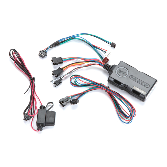
Wiring Schematic
LED's
SmartStart Module
(Top view)
Green LED
Amber LED
Data Connection
Network Status
SmartStart Module (Side view, Top down)
INSTALLATION CAUTIONS
The white plug on the 3-way cable adapter
is ONLY for use with digital platforms such as
DBALL2, DBALL2PRo, 4X10 and 5X10.
For some older analog systems with combined
4-pin ESP/D2D ports, you CANNOT use an inter-
face module in D2D mode when using a Smart-
Start module. You must use W2W on the bypass
module.
DO NOT connect the black 3-pin ESP connector
to white Door Lock port on Directed systems.
There should NEVER be more than one data plug
connected from the 3-way cable adapter.
Con guration Wires
Gray & White
5 pin Analog Cable
Cable Adapter
(see table)
4 pin
Fuse
2 pin
** Do not connect power and ground when using SmartStart
in a D2D con guration or damage may occur.
SmartStart Module to Xpresskit
¢
Pin #
Wire Color
1
White/Blue
2
Brown
3
Green
4
Blue
5
Red/White
*
NOTE: The analog output wires are only active if the
device has been configured for Analog Wire mode in the
installation portal.
3-way
Directed System
ESP (4 pin, brn)
(Top view)
or
ESP (3 pin, blk)
D2D (4 pin, wht)
Red: +12V **
Black: Ground **
NOTE: The appearance and connector/port
arrangement on the analog or digital system
being installed system may di er from the
example shown.
5-pin Analog Cable*
cut loop (see table)
Connection/Description
(-) RS (Remote Start)/AUX output
4 pin
D2D
(-) Factory horn/Alert input
(4 pin, white)
(-) Lock Output
2 pin
(-) Unlock Output
+12V
GND
(-) Trunk/AUX output
Quick Reference Install Guide
VSM300/350, DSM300/350
Installation Procedure
This product is compatible with most Directed dig-
ital systems, analog systems with ESP2/D2D data
ports, and many Autostart and AstroStart systems
with pager ports and D2D ports.
Please read the following before proceeding.
1. Customer Information required:
•
Record the customer information request-
ed in step 4a of this procedure. The mod-
ule Air ID # is provided on a sticker which
should be affixed to the space provided in
the user's guide.
This information is required for final verifi-
cation/activation of the VSM300/350 or
DSM300/350.
2. Installation Points:
•
Install and test the security/remote start
or digital system first using the associated
guides and wiring diagram. When add-
ing SmartStart to an existing system, veri-
fy it is fully functional before installing the
SmartStart module.
•
Mount the SmartStart module as high as
possible in the vehicle with the engraved
side facing upward (for all devices).
Mount with minimal obstructions that can
affect communications and within reach
of the main Directed system using the pro-
vided cables (do not extend).
The module's signal strength (RSSI) can be viewed in the
activation portal after a successful transmission test.
-50 to -90 dB
= good signal strength
-91 to -100 dB
= borderline/inconsistent signal strength
> -100 dB
= weak, insufficient signal strength
QRNDSM350 2015-03
Advertisement

Related Manuals for Directed SMARTASTART VSM300


Summary of Contents for Directed SMARTASTART VSM300
-
Page 1: Wiring Schematic
Quick Reference Install Guide VSM300/350, DSM300/350 Wiring Schematic Installation Procedure This product is compatible with most Directed dig- LED’s ital systems, analog systems with ESP2/D2D data Con guration Wires 3-way ports, and many Autostart and AstroStart systems Gray & White... - Page 2 4. Verify and Activate the SmartStart module: lowing chart). The following steps need to be performed Flashing The module is seeking cellular for the Verification/Activation of the Directed Slowly system communication. If no cell Configuration Wires Chart SmartStart module. coverage is available the Amber...