Advertisement
Quick Links
Download this manual
See also:
User Manual
*15G065026100AK*
P/N: 15G065026100AK V1.0
Quick Installation Guide
EP2C612D16NM / EP2C612D16NM-8R / EP2C612D16NM-2T / EP2C612D16NM-2T8R
The server board User's Manual is available for download from the ASRock Rack's official website
at http://www.asrockrack.com.
Take note of the following precautions before you install server board components or change any
server board settings.
1.
Unplug the power cord from the wall socket before touching any components.
2.
To avoid damaging the server board's components due to static electricity, NEVER place your
server board directly on the carpet or the like. Also remember to use a grounded wrist strap or
touch a safety grounded object before you handle the components.
3.
Hold components by the edges and do not touch the ICs.
4.
Whenever you uninstall any component, place it on a grounded anti-static pad or in the bag
that comes with the component.
5.
When placing screws into the screw holes to secure the server board to the chassis, please do
not over-tighten the screws! Doing so may damage the server board.
2
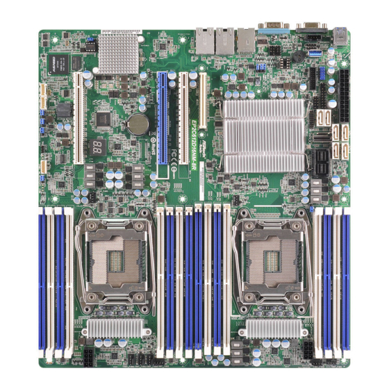
Motherboard Layout
1
2
3 4 5 6
7
USB 3.0
ATXPWR1
T: USB1
B: USB2
54
AUX_PANEL1
1
PLED PWRBTN
USB_1_2
PANEL1
USB3_3_4
1
HDLED RESET
1
1
1
1
53
52
BUZZER1
Intel
1
SATA_SGPIO2
SATA_SGPIO1
1
51
C612
1
PMBUS_SEL_CLK1
50
1
PMBUS_SEL_DAT1
49
PMBUS_SEL_ALT1
1
IPMI_LAN1
48
LAN1
3008
(NCSI)
LAN2
MEZZ1
47
PCIE7
PCIE6
Note:
EP2C612D16NM-2T / EP2C612D16NM-2T8R:
Intel X540
BATTERY1
EP2C612D16NM / EP2C612D16NM-8R:
Intel I350
(See Note)
Intel
X540
46
B 1
U
PCIE2
1
BMC
SPI_
2400
CON1
BMC_SMB2
BMC_SMB1
CHASSIS_ID1
CHASSIS_ID2
1
1
1
1
45
44
43
3
I/O Panel
1
2
3
EP2C612D16NM / EP2C612D16NM-8R
No. Description
No. Description
1
USB 3.0 Ports (USB3_1_2)
2
VGA Port (VGA1)
3
Serial Port (COM1)
EP2C612D16NM-2T / EP2C612D16NM-2T8R
No. Description
No. Description
1
USB 3.0 Ports (USB3_1_2)
2
VGA Port (VGA1)
3
Serial Port (COM1)
8
9 10
11
121314 1516 17
18
SATA_1
SATA_0
SATA_3
SATA_2
SATA_4
SATA_5
LSI_SAS_0_7
SSATA_0_3
1
1
PECI1
TPM1
CPU1_FAN1
LSI
EP2C612D16NM-2T8R
(White)
(Blue)
RoHS
Super
Dr.
I/O
Debug
CPU2_FAN1
(White)
IPMB1
CHASSIS_ID3
T 1
R
ME_RECOVERY1
1
1
1
1
42
41
40
39
38
37
4
5
6
4
LAN RJ-45 Port (IPMI_LAN1)
5
1G LAN RJ-45 Port(LAN1)
6
1G LAN RJ-45 Port (LAN2)
4
LAN RJ-45 Port (IPMI_LAN1)
5
10G LAN RJ-45 Port (LAN1)
6
10G LAN RJ-45 Port (LAN2)
1
Install the Server Board
1
Insert the server board into the chassis.
2
A f f i x t he screws clock w ise into t he
mounting holes in all of the corners of
the server board.
Do not over-tighten the screws
33.02 cm (13 in)
DDR4_A1 (64 bit, 288-pin module, Blue)
DDR4_A2 (64 bit, 288-pin module, White)
DDR4_B1 (64 bit, 288-pin module, Blue)
DDR4_B2 (64 bit, 288-pin module, White)
ATX12V1
CPU1
DDR4_D2 (64 bit, 288-pin module, White)
DDR4_D1 (64 bit, 288-pin module, Blue)
DDR4_C2 (64 bit, 288-pin module, White)
DDR4_C1 (64 bit, 288-pin module, Blue)
DDR4_E1 (64 bit, 288-pin module, Blue)
DDR4_E2 (64 bit, 288-pin module, White)
DDR4_F1 (64 bit, 288-pin module, Blue)
DDR4_F2 (64 bit, 288-pin module, White)
FRNT_FAN4
FRNT_FAN5
FRNT_FAN6
CPU2
ATX12V2
DDR4_H2 (64 bit, 288-pin module
, White
)
DDR4_H1 (64 bit, 288-pin module
, Blue
)
DDR4_G2 (64 bit, 288-pin module
, White
)
DDR4_G1 (64 bit, 288-pin module, Blue)
4
Jumper Cap On/Off
When the jumper cap is placed on the pins, the
jumper is "Short". If no jumper cap is placed on the
pins, the jumper is "Open".
The illustration shows a 3-pin jumper whose pin1
and pin2 are "Short" when a jumper cap is placed on
these 2 pins.
www.asrockrack.com
No.
Description
1
Speaker Header (SPEAKER1)
2
LAN LED Connector (LED_LAN34)
3
Vertical Type A USB 3.0 (USB3_5)
4
USB 3.0 Header (USB3_3_4)
19
5
USB 2.0 Header (USB_1_2)
20
6
Auxiliary Panel Header (AUX_PANEL1)
21
22
7
ATX Power Connector (ATXPWR1)
8
SATA3 Connector (SATA_5)
23
9
SATA3 Connector (SATA_4)
10
SATA3 Connector (SATA_1)
24
11
SATA3 Connector (SATA_3)
12
SATA3 Connector (SATA_0)
13
SATA3 Connector (SATA_2)
14
Mini-SAS Connector (SSATA_0_3)
Mini SAS HD Connector (LSI_SAS_0_7)
25
15
*Only for EP2C612D16NM-8R / EP2C612D16NM-2T8R
26
16
TPM Header (TPM1)
17
CPU 1 Fan Connector (CPU1_FAN1)
18
CPU PECI Mode Jumper (PECI1)
27
19
2 x 288-pin DDR4 DIMM Slots (DDR4_A2, DDR4_B2, White)
28
20
Front Fan Connector (FRNT_FAN1)
29
21
2 x 288-pin DDR4 DIMM Slots (DDR4_A1, DDR4_B1, Blue)
30
22
Front Fan Connector (FRNT_FAN2)
31
23
ATX 12V Power Connector (ATX12V1)
32
24
LGA 2011 CPU Socket R3 (Narrow ILM) (CPU1)
33
25
2 x 288-pin DDR4 DIMM Slots (DDR4_C2, DDR4_D2, White)
26
2 x 288-pin DDR4 DIMM Slots (DDR4_C1, DDR4_D1, Blue)
34
27
2 x 288-pin DDR4 DIMM Slots (DDR4_E1, DDR4_F1, Blue)
28
2 x 288-pin DDR4 DIMM Slots (DDR4_E2, DDR4_F2, White)
29
Front Fan Connector (FRNT_FAN3)
35
30
Front Fan Connector (FRNT_FAN4)
36
31
Front Fan Connector (FRNT_FAN5)
32
Front Fan Connector (FRNT_FAN6)
33
LGA 2011 CPU Socket R3 (Narrow ILM) (CPU2)
34
ATX 12V Power Connector (ATX12V2)
35
2 x 288-pin DDR4 DIMM Slots (DDR4_H2, DDR4_G2, White)
36
2 x 288-pin DDR4 DIMM Slots (DDR4_H1, DDR4_G1, Blue)
37
CPU 2 Fan Connector (CPU2_FAN1)
38
Intelligent Platform Management Bus header (IPMB1)
39
ME Recovery Jumper (ME_RECOVERY1)
40
Thermal Sensor Header (TR1)
41
Chassis ID3 Jumper (CHASSIS_ID3)
42
Chassis ID2 Jumper (CHASSIS_ID2)
43
Chassis ID1 Jumper (CHASSIS_ID1)
44
BMC SMBus Header 1 (BMC_SMB1)
45
BMC SMBus Header 2 (BMC_SMB2)
46
NCSI Mode Jumper (NCSI_SEL1)
47
Mezzanine Slot (MEZZ1)
48
PMBUS Mode Jumper (PMBUS_SEL_ALT1)
49
PMBUS Mode Jumper (PMBUS_SEL_DAT1)
50
PMBUS Mode Jumper (PMBUS_SEL_CLK1)
51
SATA SGPIO Connector 1 (SATA_SGPIO1)
52
SATA SGPIO Connector 2 (SATA_SGPIO2)
53
System Panel Header (PANEL1)
54
PSU SMBus (PSU_SMB1)
Advertisement

Related Manuals for ASROCK Rack EP2C612D16NM


Summary of Contents for ASROCK Rack EP2C612D16NM
- Page 1 EP2C612D16NM / EP2C612D16NM-8R / EP2C612D16NM-2T / EP2C612D16NM-2T8R www.asrockrack.com Install the Server Board The server board User's Manual is available for download from the ASRock Rack's official website at http://www.asrockrack.com. Take note of the following precautions before you install server board components or change any Insert the server board into the chassis.
-
Page 2: Quick Installation Guide
Quick Installation Guide EP2C612D16NM / EP2C612D16NM-8R / EP2C612D16NM-2T / EP2C612D16NM-2T8R www.asrockrack.com Install the Processor Install the CPU Fan and Heatsink Connect the CPU fan to the CPU Apply the thermal grease. Install the Open the socket levers and the Close the socket levers. Remove Install the processor and close FAN connector.
Need help?
Do you have a question about the EP2C612D16NM and is the answer not in the manual?
Questions and answers