Table of Contents

Related Manuals for Fluke 9142


Summary of Contents for Fluke 9142
- Page 1 9142, 9143, 9144 Field Metrology Well User’s Guide PN 3720986 February 2013 © 2013 Fluke Corporation. All rights reserved. Specifications are subject to change without notice. All product names are trademarks of their respective companies.
-
Page 3: Table Of Contents
Table of Contents Before You Start ...............1 Introduction ....................1 Unpacking ....................2 Symbols Used ................... 3 Safety Information ..................4 1.4.1 Warnings ......................5 1.4.2 Cautions ......................7 CE Comments ................... 8 1.5.1 EMC Directive ....................8 1.5.2 Immunity Testing .....................8 1.5.3 Emission Testing ....................9 1.5.4 Low Voltage Directive (Safety) ................9... - Page 4 Maintenance ................33 Field Metrology Well Performance Analysis ........... 33...
- Page 5 Tables Table 1 Symbols used ..................3 Table 2 Base Unit Specifications ..............11 Table 3 -P Option Specifications ..............12...
- Page 6 Figure 2 914X Field Metrology Well ..............16 Figure 3 Display panel and keys ..............18 Figure 4 914X display ..................19 Figure 5 9142 power panel ................21 Figure 6 9143 and 9144 power panel .............. 21 Figure 7 -P option panel ................. 22 Figure 8 Probe connector wiring ..............
-
Page 7: Before You Start
Before You Start Introduction Before You Start Introduction... -
Page 8: Unpacking
914X Field Metrology Wells Unpacking Unpacking ● ● ● ● ● ● ● ● ● ● ● ● ● ● ● ● ● ● ● ● ● ● ● ● ●... -
Page 9: Symbols Used
Before You Start Symbols Used ● ● ● ● ● ● ● ● ● ● ● ● Symbols Used Table 1 Symbols used Symbol Description AC (Alternating Current) AC-DC Battery Complies with European Union directives Double Insulated... -
Page 10: Safety Information
914X Field Metrology Wells Safety Information Symbol Description Electric Shock Fuse PE Ground Hot Surface (Burn Hazard) Read the User’s Guide (Important Information) Canadian Standards Association C-TICK Australian EMC mark The European Waste Electrical and Electronic Equipment (WEEE) Directive (2002/96/ EC) mark. -
Page 11: Warnings
Before You Start Safety Information 1.4.1 Warnings... - Page 12 914X Field Metrology Wells Safety Information...
-
Page 13: Cautions
Before You Start Safety Information 1.4.2 Cautions... -
Page 14: Ce Comments
914X Field Metrology Wells CE Comments CE Comments 1.5.1 EMC Directive 1.5.2 Immunity Testing... -
Page 15: Emission Testing
Before You Start Authorized Service Centers connector clamp-on ferrite probe Figure 1 Clamp-on ferrite installation 1.5.3 Emission Testing 1.5.4 Low Voltage Directive (Safety) Authorized Service Centers... - Page 16 914X Field Metrology Wells Authorized Service Centers ● ● ● ●...
-
Page 17: Specifications And Environmental Conditions
Specifications and Environmental Conditions Specifications Specifications and Environmental Conditions Specifications Table 2 Base Unit Specifications Base Unit Specifications 9142 9143 9144 Temperature Range at –25 °C to 150 °C 33 °C to 350 °C 50 °C to 660 °C 23 °C (-13 °F to 302 °F) (91 °F to 662 °F) (122 °F to 1220 °F) - Page 18 914X Field Metrology Wells Specifications Base Unit Specifications 9142 9143 9144 Weight 8.16 kg (18 lbs) 7.3 kg (16 lbs) 7.7 kg (17 lbs) Power Requirements 100 V to 115 V (± 10 %) 100 V to 115 V (± 10 %), 50/60 Hz, 1400 W 50/60 Hz, 575 W 230 V (± 10%), 50/60 Hz, 1800 W...
-
Page 19: Environmental Conditions
Specifications and Environmental Conditions Environmental Conditions -P Specifications Built-in TC Thermometer Readout Accuracy Type J: ± 0.7 °C at 660 °C Type K: ± 0.8 °C at 660 °C Type T: ± 0.8 °C at 400 °C Type E: ± 0.7 °C at 660 °C Type R: ±... -
Page 21: Quick Start
Quick Start Setup Quick Start Setup Note: The instrument will not heat, cool, or control until the “SET PT.” parameter is “Enabled”. -
Page 23: Parts And Controls
Quick Start Parts and Controls 3.2.1 Display Panel udlr... -
Page 25: Figure 4 914X Display
Quick Start Parts and Controls Figure 4 914X display... -
Page 26: Power Panel
914X Field Metrology Wells Parts and Controls 3.2.3 Power Panel... -
Page 27: Figure 5 9142 Power Panel
Quick Start Parts and Controls Figure 5 9142 power panel Figure 6 9143 and 9144 power panel... -
Page 28: P Option Panel (-P Models Only)
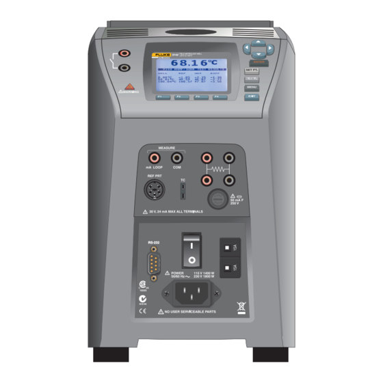
914X Field Metrology Wells Parts and Controls 3.2.4 -P Option Panel (-P models only) MEASURE mA LOOP REF PRT 50 mA F 250 V 30 V, 24 mA MAX ALL TERMINALS Figure 7 -P option panel... -
Page 29: Figure 8 Probe Connector Wiring
Quick Start Parts and Controls Probe Connector Shield RTD Sensor Figure 8 Probe connector wiring... -
Page 30: Languages
914X Field Metrology Wells Languages Figure 9 Jumper locations for 3-wire and 2-wire connections Languages ● ● ● 3.3.1 Language Selection... -
Page 31: Reset To English Language
Quick Start Languages Figure 10 Steps to language selection 3.3.2 Reset to English Language Note: The F1 and F4 English shortcut override is temporary. If you toggle the power off, the instrument jwill return to the language selected in the DISPLAY SETUP menu rather than coming up in English. -
Page 33: Menu Structure
Menu Structure Temp Setup Menu Menu Structure Temp Setup Menu Figure 11 Main Menu - Temp SetUp... -
Page 34: Prog Menu
914X Field Metrology Wells Prog Menu Prog Menu Figure 12 Main Menu - Prog Menu... -
Page 35: Switch Test Parameters
Menu Structure Prog Menu 4.2.1 Switch Test Parameters 4.2.2 Switch Test Description CAUTION: The switch, switch wires, switch components and switch accessories can be damaged if the Field Metrology Well exceeds their temperature limits. -
Page 36: Figure 13 Auto And Manual Switch Test Operation Example
914X Field Metrology Wells Prog Menu Figure 13 Auto and manual switch test operation example... -
Page 37: System Menu
Menu Structure System Menu System Menu Figure 14 Main Menu - System Menu... -
Page 38: Input Setup (-P Only)
914X Field Metrology Wells Input Setup (-P only) Input Setup (-P only) Figure 15 Main Menu - Input Setup... - Page 39 Maintenance Field Metrology Well Performance Analysis Maintenance ● ● ● ● ● ● ● ● ● ● ● Field Metrology Well Performance Analysis...
- Page 40 914X Field Metrology Wells Field Metrology Well Performance Analysis...
Need help?
Do you have a question about the 9142 and is the answer not in the manual?
Questions and answers