Advertisement
Quick Links
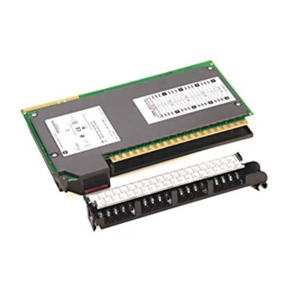
Installation Instructions
Cat. No. 1771-ID16 Series B
Use this document as a guide when installing the ac Isolated Input
module.
This module must be used in a series B or later 1771 I/O chassis. The
1771-ID16 is not compatible with the 1771-AL local I/O adapter.
This module contains customer-selectable input filtering to limit the
effects of voltage transients caused by contact bounce and/or radiated
electrical noise. The delay due to filtering is 9.0 or 18.0ms for
turning ac inputs on to off, and 0.57ms for turning ac inputs off to
on: 9.0ms for turning dc inputs on to off, and 0.57ms for turning dc
inputs off to on. The filter time is factory set to 9.0ms.
The module is designed to operate with limit switches, float
switches, selector switches, and pushbutton switches.
Advertisement

Related Manuals for Rockwell Automation 1771-ID16


Summary of Contents for Rockwell Automation 1771-ID16
- Page 1 This module must be used in a series B or later 1771 I/O chassis. The 1771-ID16 is not compatible with the 1771-AL local I/O adapter. This module contains customer-selectable input filtering to limit the effects of voltage transients caused by contact bounce and/or radiated electrical noise.
- Page 2 In no event will Rockwell Automation be responsible or liable for indirect or consequential damage resulting from the use or application of these products.
- Page 3 ac/dc (120V) Isolated Input Module Identifies information that is critical for successful application and understanding of the IMPORTANT product. ATTENTION This equipment is intended for use in a Pollution Degree 2 industrial environment, in overvoltage Category II applications (as defined in IEC publication 60664–1), at altitudes up to 2000 meters without derating.
- Page 4 ac/dc (120V) Isolated Input Module The isolated input module is shipped in a static-shielded packaging to guard against electrostatic discharge damage. Observe the following precautions when handling the module. ATTENTION This equipment is sensitive to electrostatic discharge, which can cause internal damage and affect normal operation.
- Page 5 ac/dc (120V) Isolated Input Module To set the filtering time, proceed as follows: 1. Remove the side covers from the module circuit board by removing the four screws securing the covers to the module and remove the circuit board. 2. Position the jumpers as required to provide the filter time you require (see below).
- Page 6 ac/dc (120V) Isolated Input Module Place your module in any slot in the chassis except the leftmost slot which is reserved for processors or adapters. Observe the following precautions ATTENTION when inserting or removing keys: insert or remove keys with your fingers make sure that key placement is correct...
- Page 7 ac/dc (120V) Isolated Input Module The 1771–ID16/B module is a modular component of the 1771 I/O system requiring a properly installed system chassis. Refer to publication 1771–IN075 for detailed information on acceptable chassis, proper installation and grounding requirements. Limit the maximum adjacent slot power dissipation to 10W maximum.
- Page 8 ac/dc (120V) Isolated Input Module Connections to the input module are made to the 40 terminal field wiring arm (cat. no. 1771-WN) shipped with the module. Attach the wiring arm to the pivot bar on the bottom of the I/O chassis. The wiring arm pivots upward and connects with the module so you can install or remove the module without disconnecting the wires.
- Page 9 ac/dc (120V) Isolated Input Module Maintain isolation between phases to prevent ATTENTION module damage.
- Page 10 1771-OA, 1771-OD or 1771-OP) to directly IMPORTANT drive terminals on an ac/dc (120V) input module (cat. no. 1771-ID16), but you must use a 2.5K, 10W resistor between the output terminal and L2 (common) as shown in the following figure.
- Page 11 ac/dc (120V) Isolated Input Module The module has 17 indicators (below), consisting of 16 input status indicators and an active indicator. The 16 status indicators will light when the field load has been applied to the field wiring arm of the module.
- Page 12 ac/dc (120V) Isolated Input Module WARNING AVERTISSEMENT...
- Page 13 ac/dc (120V) Isolated Input Module...
- Page 14 ac/dc (120V) Isolated Input Module...
- Page 15 ac/dc (120V) Isolated Input Module...
Need help?
Do you have a question about the 1771-ID16 and is the answer not in the manual?
Questions and answers