Table of Contents
Advertisement
Quick Links
Advertisement
Table of Contents

Related Manuals for VIA Technologies EPIA-E900-12Q


Summary of Contents for VIA Technologies EPIA-E900-12Q
- Page 1 USER MANUAL EPIA-E900 Pico-ITXe board 1.01-02162017-111600...
- Page 2 VIA Technologies, Inc. reserves the right the make changes to the products described in this manual at any time without prior notice. Regulatory Compliance FCC-A Radio Frequency Interference Statement This equipment has been tested and found to comply with the limits for a class A digital device, pursuant to part 15 of the FCC rules.
-
Page 3: Safety Precautions
Battery Recycling and Disposal Only use the appropriate battery specified for this product. Do not re-use, recharge, or reheat an old battery. Do not attempt to force open the battery. Do not discard used batteries with regular trash. Discard used batteries according to local regulations. Safety Precautions Always read the safety instructions carefully. -
Page 4: Box Contents
EPIA-E900 User Manual Box Contents EPIA-E900-12QE 1 x EPIA-E900 board 1 x SATA cable 1 x SATA power cable 1 x DC-in power cable Ordering Information Part Number Description ® EPIA-E900-12QE Pico-ITXe board with 1.2GHz VIA Eden X4 processor, Mini HDMI, 2 x USB 3.0, 2 x USB 2.0, 2 x COM, 2 x Gigabit Ethernet, SATA and 12V DC-in Optional Accessories... -
Page 5: Table Of Contents
EPIA-E900 User Manual Table of Contents 1. Product Overview ........................1 1.1. Key Features and Benefits ..........................1 ® 1.1.1. VIA Eden X4 Processor ..........................1 1.1.2. VIA VX11H MSP Chipset ...........................1 1.1.3. Expansion Option ............................1 1.2. Product Specifications .............................2 1.3. Layout Diagram ..............................5 1.4. - Page 6 EPIA-E900 User Manual 6.4.5. System Time .............................. 42 6.5. Advanced Settings ............................43 6.5.1. ACPI Settings ............................. 44 6.5.1.1. Enable Hibernation ........................44 6.5.1.2. ACPI Sleep State ..........................44 6.5.2. S5 RTC Wake Settings ..........................45 6.5.2.1. Wake system with Fixed Time ....................45 6.5.2.2.
- Page 7 EPIA-E900 User Manual 6.10.3. Save Changes and Reset ......................... 62 6.10.4. Discard Changes and Reset ........................62 6.10.5. Save Changes ............................63 6.10.6. Discard Changes ............................63 6.10.7. Save as User Defaults ..........................63 6.10.8. Restore User Defaults ..........................63 7.
- Page 8 EPIA-E900 User Manual List of Figures Figure 1: Top side layout diagram .............................5 Figure 2: Bottom side layout diagram ..........................6 Figure 3: Top side dimensions (without heatsink) diagram ..................7 Figure 4: Front panel side dimensions diagram ......................7 Figure 5: Back panel side dimensions diagram .......................7 Figure 6: Top side height distribution diagram .......................8 Figure 7: Bottom side height distribution diagram......................8 Figure 8: Front panel I/O diagram .............................9...
- Page 9 EPIA-E900 User Manual Figure 58: Illustration of Chipset Settings screen ......................54 Figure 59: Illustration of DRAM Configuration screen ....................55 Figure 60: Illustration of Video Configuration screen ....................56 Figure 61: Illustration of PMU_ACPI Configuration screen ..................57 Figure 62: Illustration of Other Control screen ......................57 Figure 63: Illustration of Others Configuration screen ....................
- Page 10 EPIA-E900 User Manual List of Tables Table 1: Top side layout description table ........................5 Table 2: Bottom side layout description table ......................6 Table 3: Layout description table of external I/O ports ....................9 Table 4: COM port pinouts .............................. 11 Table 5: USB 3.0 port pinouts ............................12 Table 6: Gigabit Ethernet port pinout ...........................
-
Page 11: Product Overview
EPIA-E900 User Manual 1. Product Overview ® The EPIA-E900 is a highly integrated Pico-ITXe board powered by a 1.2GHz VIA Eden X4 processor and VIA VX11H MSP chipset that delivers a high performance and rich multimedia features in an ultra-compact package for a wide range of embedded system applications such as industrial automation, transportation, medical, and infotainment. -
Page 12: Product Specifications
EPIA-E900 User Manual 1.2. Product Specifications Processor ® 1.2GHz VIA Eden 21mm x 21mm FCBGA Chipset VIA VX11H MSP chipset 33mm x 33mm FCBGA Graphics Integrated C-640 DX11 3D/2D graphics and video processor with MPEG-2, WMV9, VC1, and ... - Page 13 EPIA-E900 User Manual Front Panel I/O 1 x HDD LED 1 x Power LED 1 x Power button 2 x USB 3.0 ports 2 x COM ports Back Panel I/O 2 x Gigabit Ethernet ports ...
- Page 14 EPIA-E900 User Manual Operating Conditions Operating Temperature 0°C ~55°C Operating Humidity 0% ~ 95% (relative humidity; non-condensing) Form Factor Pico-ITXe (13.8cm x 7.2cm) Compliance Note: As the operating temperature provided in the specifications is a result of the test performed in VIA’s chamber, a number of variables can influence this result.
-
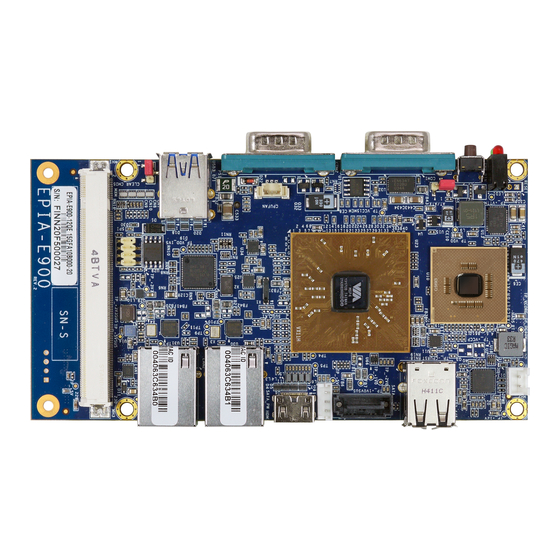
Page 15: Layout Diagram
EPIA-E900 User Manual 1.3. Layout Diagram Figure 1: Top side layout diagram Item Description PWR: DC-in connector SATA: SATA connector SATA_PW: SATA power connector MXM: MXM connector SPI: SPI pin header CLEAR_CMOS: Clear CMOS jumper CPUFAN: CPU fan connector AT/ATX: AT/ATX mode jumper Chipset: VIA VX11H MSP CPU: 1.2GHz VIA Eden X4 processor Table 1: Top side layout description table... -
Page 16: Figure 2: Bottom Side Layout Diagram
EPIA-E900 User Manual Figure 2: Bottom side layout diagram Item Description SODIMM: DDR3 SODIMM slot LPC: LPC connector JWLAN: USB 2.0 connector CMOS battery connector Table 2: Bottom side layout description table... -
Page 17: Dimensions
EPIA-E900 User Manual 1.4. Dimensions Figure 3: Top side dimensions (without heatsink) diagram Figure 4: Front panel side dimensions diagram Figure 5: Back panel side dimensions diagram... -
Page 18: Height Distribution
EPIA-E900 User Manual 1.5. Height Distribution Figure 6: Top side height distribution diagram Figure 7: Bottom side height distribution diagram... -
Page 19: I/O Interface
EPIA-E900 User Manual 2. I/O Interface The VIA EPIA-E900 has a wide selection of interfaces. It includes a selection of frequently used ports as part of the external I/O coastline. 2.1. External I/O Ports Figure 8: Front panel I/O diagram Figure 9: Back Panel I/O diagram Item Description... -
Page 20: Led Indicators
EPIA-E900 User Manual 2.1.1. LED Indicators There are two LEDs on the front panel that indicates the status of the system: HDD LED flashes in red and indicates hard drive storage activity for SATA drive. Power Status LED flashes in green and indicates the system’s power status. Figure 10: LED indicators diagram 2.1.2. -
Page 21: Com Port
EPIA-E900 User Manual 2.1.3. COM Port The EPIA-E900 provides two COM (D-sub 9-pin male) ports located on the front panel. The COM ports labeled as COM1 and COM2 supports RS-232 standard. The pinout of the COM ports are shown below. Figure 12: COM port diagram COM 1 COM 2... -
Page 22: Usb 3.0 Port
EPIA-E900 User Manual 2.1.4. USB 3.0 Port There are two USB 3.0 ports also known as SuperSpeed USB located on the front panel. The USB 3.0 port has a maximum data transfer rate up to 5Gbps and offers a backwards compatible with previous USB 2.0 specifications. -
Page 23: Gigabit Ethernet Port
EPIA-E900 User Manual 2.1.5. Gigabit Ethernet Port The EPIA-E900 is equipped with two Gigabit Ethernet ports. The Gigabit Ethernet ports uses 8 Position 8 Contact (8P8C) receptacle connector or commonly referred to as RJ-45. It is fully compliant with IEEE 802.3 (10BASE-T), 802.3u (100BASE-TX), and 802.3ab (1000BASE-T) standards. -
Page 24: Mini Hdmi Port
EPIA-E900 User Manual ® 2.1.6. Mini HDMI Port The integrated 19-pin Mini HDMI port uses an HDMI Type C receptacle connector as defined in the ® ® HDMI specification. The Mini HDMI port is for connecting to HDMI displays. The pinout of the Mini HDMI port is shown below. -
Page 25: Usb 2.0 Port
EPIA-E900 User Manual 2.1.7. USB 2.0 Port The EPIA-E900 provides two USB 2.0 ports that gives complete Plug and Play and hot swap capability for external devices. The USB interface complies with USB UHCI, Rev. 2.0. The pinout of the USB 2.0 port is shown below. -
Page 26: Onboard Connectors
EPIA-E900 User Manual 2.2. Onboard Connectors 2.2.1. DC-In Connector The mainboard has an onboard DC-in 2-pin power connector to connect the DC-in power cable. The DC- in connector is labeled as “PWR”. The pinout of the DC-in power connector is shown below. Figure 17: DC-in connector diagram Signal DC_+12V... -
Page 27: Sata Connector
EPIA-E900 User Manual 2.2.2. SATA Connector The SATA connector onboard can support up to 3 Gbps transfer speeds. The SATA connector is labeled as “SATA”. The pinout of the SATA connector is shown below. Figure 18: SATA connector diagram Signal STXP_0 STXN_0 SRXN_0... -
Page 28: Sata Power Connector
EPIA-E900 User Manual 2.2.3. SATA Power Connector The onboard SATA power connector provides both +5V and +12V directly through the mainboard to the SATA drives. The SATA power connector is labeled as “SATA_PW”. The pinout of the SATA power connector is shown below. Figure 19: SATA power connector diagram Signal +12V... -
Page 29: Spi Pin Header
EPIA-E900 User Manual 2.2.4. SPI Pin Header The mainboard has one 8-pin SPI pin header. The SPI (Serial Peripheral Interface) pin header is used to connect to the SPI BIOS programming fixture. The pin header is labeled as “SPI”. The pinout of the pin header is shown below. -
Page 30: Cpu Fan Connector
EPIA-E900 User Manual 2.2.5. CPU Fan Connector The CPU fan connector onboard runs on +12V and maintain CPU cooling. The fan provides variable fan speeds controlled by the BIOS. The CPU fan connector is labeled as “CPUFAN”. The pinout of the CPU fan connector is shown below. -
Page 31: Cmos Battery Connector
EPIA-E900 User Manual 2.2.6. CMOS Battery Connector The mainboard is equipped with onboard CMOS battery connector used for connecting the external cable battery that provides power to the CMOS RAM. If disconnected all configurations in the CMOS RAM will be reset to factory defaults. The connector pinout is shown below. Figure 22: CMOS battery connector diagram Signal +3.3VBAT... -
Page 32: Usb 2.0 Connector
EPIA-E900 User Manual 2.2.7. USB 2.0 Connector The EPIA-E900 is equipped with onboard USB 2.0 connector labeled as “JWLAN” for WLAN USB (Wi-Fi) module. The pinout of the USB 2.0 connector is shown below. Figure 23: USB 2.0 connector diagram Signal +5VSUS USBHP_N8... -
Page 33: Lpc Connector
EPIA-E900 User Manual 2.2.8. LPC Connector The EPIA-E900 board has one LPC connector for debugging purposes. The connector is labeled as “LPC”. The pinout of the connector is shown below. Figure 24: LPC connector diagram Signal LPCAD2 LPCAD3 LPCAD1 -LPCFRAME LPCAD0 LPC33CLK -LPCRST... -
Page 34: Jumpers
EPIA-E900 User Manual 3. Jumpers Jumper Description A jumper consists of pair conductive pins used to close in or bypass an electronic circuit to set up or configure particular feature using a jumper cap. The jumper cap is a small metal clip covered by plastic. It performs like a connecting bridge to short (connect) the pair of pins. -
Page 35: Clear Cmos Jumper
EPIA-E900 User Manual 3.1. Clear CMOS Jumper The onboard CMOS RAM stores system configuration data and has an onboard battery power supply. To reset the CMOS settings, set the jumper on pins 2 and 3 while the system is off. Return the jumper to pins 1 and 2 afterwards. -
Page 36: At/Atx Power Mode Select Jumper
EPIA-E900 User Manual 3.2. AT/ATX Power Mode Select Jumper The AT/ATX mode jumper enables the mainboard to switch between two power modes: AT and ATX. The power mode can set by changing the jumper position. The jumper is labeled as “AT/ATX”. The jumper settings are shown below. -
Page 37: Expansion Connectors
EPIA-E900 User Manual 4. Expansion Connectors 4.1. MXM Connector The MXM connector labeled as “MXM” is an onboard expansion connector for connecting E900-A expansion board to the mainboard. The location and pinout of the MXM connector are shown below. Figure 28: MXM connecter diagram Signal Signal DVP_D0... - Page 38 EPIA-E900 User Manual LPC33CLK -LPCFRAME SERIRQ -LPCDRQ1 AZ_SYNC SMB_CK -AZ_RST SMB_DT AZ_BIT_CLK AZ_SDIN0 AZ_SDOUT USBHP3- USBHP2- USBHP3+ USBHP2+ USBHP1- USBHP0- USBHP1+ USBHP0+ LVDS0D0+ LVDS0D0- LVDS0D1+ LVDS0D1- LVDS0D2+ LVDS0D2- LVDSENVDD LVDSENVEE LVDS0D3+ LVDS0D3- LVDS0CLK+ VX11_RI2 LVDS0CLK- VX11_DCD2 LVDSPWM0 VX11_SOUT2 LVDSSPDAT VX11_SIN2 LVDSSPCLK VX11_CTS2 VX11_DSR2...
-
Page 39: Table 20: Mxm Connector Pinout
EPIA-E900 User Manual DP0TX0+ HDMI0SPD DP0TX0- HDMI0SPC DP0_HPD HDMI0_CEC PCIE_CLK_REF+ -PEXWAKE PCIE_CLK_REF- -PEX1_RST PETP3 PEXRX3+ PETN3 PEXRX3- PETP2 PEXRX2+ PETN2 PEXRX2- PETP1 PEXRX1+ PETN1 PEXRX1- PETP0 PEXRX0+ PETN0 PEXRX0- GPI6 GPO16 GPI22 GPO20 GPI23 GPO21 SPKR FANIO2 FAN_CTL2 MSPIDI MSPISS0 MSPIDO MSPISS1 MSPICLK... -
Page 40: Ddr3 Sodimm Memory Slot
EPIA-E900 User Manual 4.2. DDR3 SODIMM Memory Slot The mainboard has one 204-pin DDR3 SODIMM slot that supports non-ECC DDR3 1333 SODIMM memory module. The memory slot labeled as “SODIMM” can accommodate up to 8GB of DDR3 1333 memory. The location of the DDR3 SODIMM memory slot is shown below. Figure 29: DDR3 SODIMM memory slot diagram... -
Page 41: Installing A Memory Module
EPIA-E900 User Manual 4.2.1. Installing a Memory Module Step 1 Align the notch on the SODIMM memory module with the protruding wedge on the SODIMM memory slot. Insert the SODIMM memory module at a 30 degree angle relative to the SODIMM memory slot. Figure 30: Inserting the memory module Step 2 Push down the SODIMM memory module until the locking clips lock the module into place. -
Page 42: Removing A Memory Module
EPIA-E900 User Manual 4.2.2. Removing a Memory Module Step 1 To disengage the locking clips, push the locking clips horizontally outward away from the SODIMM memory module. Figure 32: Disengaging the SODIMM locking clips Step 2 When the locking clips have cleared, the SODIMM memory module will automatically pop up to the 30 degree angle. -
Page 43: Hardware Installation
EPIA-E900 User Manual 5. Hardware Installation This chapter provides information about hardware installation procedures. 5.1. Installing the VNT9271 USB Wi-Fi Dongle Step 1 Locate a USB 2.0 or USB 3.0 port on the panel I/O. Step 2 Insert the VNT9271 USB Wi-Fi dongle into the USB 2.0 or USB 3.0 port. Figure 34: Inserting the VNT9271 USB Wi-Fi module... -
Page 44: Installing The Emio-1533 Usb Wi-Fi Module
EPIA-E900 User Manual 5.2. Installing the EMIO-1533 USB Wi-Fi Module Step 1 Mount the EMIO-1533 to the prepared standoff in the chassis. Align the two mounting holes on the EMIO- 1533 module with the mounting holes on the standoffs. And then secure the EMIO-1533 module in place with two screws. -
Page 45: Figure 37: Installing Wi-Fi Antenna Cable Diagram
EPIA-E900 User Manual Step 3 Insert the Wi-Fi antenna cable into the antenna hole from the inside of the panel I/O plate. Insert the toothed washer, fasten it with the nut and install the external antenna. Figure 37: Installing Wi-Fi antenna cable diagram Step 4 Connect the other end of the Wi-Fi antenna cable to the micro-RF connector labeled “IPEX”... -
Page 46: Installing The Emio-5531 Usb Wi-Fi + Bluetooth Module
EPIA-E900 User Manual 5.3. Installing the EMIO-5531 USB Wi-Fi + Bluetooth Module Step 1 Mount the EMIO-5531 to the prepared standoff in the chassis. Align the two mounting holes on the EMIO- 5531 module with the mounting holes on the standoffs. And then secure the EMIO-5531 module in place with two screws. -
Page 47: Figure 41: Installing Wi-Fi Antenna Cable Diagram
EPIA-E900 User Manual Step 3 Insert the Wi-Fi antenna cable into the antenna hole from the inside of the panel I/O plate. Insert the toothed washer, fasten it with the nut and install the external antenna. Figure 41: Installing Wi-Fi antenna cable diagram Step 4 Connect the other end of the Wi-Fi antenna cable to the micro-RF connector labeled “IPEX”... -
Page 48: Installing Into A Chassis
EPIA-E900 User Manual 5.4. Installing into a Chassis The EPIA-E900 can be fitted into any chassis that has the mounting holes compatible with the standard Pico-ITXe mounting hole locations. Additionally, the chassis must meet the minimum height requirements for specified areas of the mainboard. 5.4.1. -
Page 49: Suggested Minimum Chassis Height
EPIA-E900 User Manual 5.4.2. Suggested minimum chassis height The figure below shows the suggested minimum height requirements for the internal space of the chassis. It is not necessary for the internal ceiling to be evenly flat. What is required is that the internal ceiling height must be strictly observed for each section that is highlighted. -
Page 50: Suggested Keepout Areas
EPIA-E900 User Manual 5.4.3. Suggested keepout areas The figure below shows the areas of the mainboard that is highly suggested to leave unobstructed. Figure 45: Suggested keepout areas (top side) Figure 46: Suggested keepout areas (bottom side) -
Page 51: Bios Setup Utility
EPIA-E900 User Manual 6. BIOS Setup Utility 6.1. Entering the BIOS Setup Utility Power on the computer and press Delete during the beginning of the boot sequence to enter the BIOS Setup Utility. If the entry point has passed, restart the system and try again. 6.2. -
Page 52: System Overview
EPIA-E900 User Manual 6.4. System Overview The System Overview screen is the default screen that is shown when the BIOS Setup Utility is launched. This screen can be accessed by traversing the navigation bar to the “Main” label. Figure 47: Illustration of the Main menu screen 6.4.1. -
Page 53: Advanced Settings
EPIA-E900 User Manual 6.5. Advanced Settings The Advanced Settings screen shows a list of categories that can provide access to a sub-screen. Sub- screen links can be identified by the preceding right-facing arrowhead. Figure 48: Illustration of the Advanced Settings screen The Advanced Settings screen contains the following links: ACPI Settings S5 RTC Wake Settings... -
Page 54: Acpi Settings
EPIA-E900 User Manual 6.5.1. ACPI Settings ACPI grants the operating system direct control over system power management. The ACPI Configuration screen can be used to set a number of power management related functions. Figure 49: Illustration of the ACPI Settings screen 6.5.1.1. -
Page 55: S5 Rtc Wake Settings
EPIA-E900 User Manual 6.5.2. S5 RTC Wake Settings Figure 50: Illustration of the S5 RTC Wake Settings screen 6.5.2.1. Wake system with Fixed Time Enable or disable system wake on alarm event. When enabled, system will wake on the hr:min:sec specified. -
Page 56: Cpu Configuration
EPIA-E900 User Manual 6.5.3. CPU Configuration The CPU Configuration screen shows detailed information about the built-in processor. In addition to the processor information, the thermal controls can be set. Figure 51: Illustration of CPU Configuration screen... -
Page 57: Sata Configuration
EPIA-E900 User Manual 6.5.4. SATA Configuration The SATA Configuration screen allows the user to view and configure the settings of the SATA configuration settings. Figure 52: Illustration of SATA Configuration screen 6.5.4.1. SATA Mode This option allows the user to manually configure SATA controller for a particular mode. IDE Mode Set this value to change the SATA to IDE mode. -
Page 58: Usb Configuration
EPIA-E900 User Manual 6.5.5. USB Configuration The USB Configuration screen shows the number of connected USB devices. Figure 53: Illustration of PC Health Status screen 6.5.5.1. Legacy USB Support The Legacy USB Support feature enables environments that do not have native USB support to use USB devices. -
Page 59: Ehci Hand-Off
EPIA-E900 User Manual 6.5.5.4. EHCI Hand-off This is a workaround feature for Operating Systems without EHCI hand-off support. The EHCI ownership change must be claimed by EHCI Driver. Enabled This option enables EHCI hand-off support. Disabled This option disables EHCI hand-off support. 6.5.5.5. -
Page 60: F81801 Super Io Configuration
EPIA-E900 User Manual 6.5.6. F81801 Super IO Configuration The F81801 Super IO Configuration screen allows the user to set system Super IO Chip parameters Figure 54: Illustration of F81801 Super IO Configuration screen 6.5.6.1. Serial Port 0 Configuration Set parameters of Serial Port 0 (COMA). 6.5.6.1.1. -
Page 61: F81801 H/W Monitor
EPIA-E900 User Manual 6.5.7. F81801 H/W Monitor F81801 screen shows F81801 H/W Monitor status. Figure 55: Illustration of F81801 H/W Monitor 6.5.7.1. Smart Fan This feature has 2 options: Enable or Disable Smart Fan. -
Page 62: Clock Generator Configuration
EPIA-E900 User Manual 6.5.8. Clock Generator Configuration The Clock Generator Configuration screen enables access to the Spread Spectrum Setting feature. Figure 56: Illustration of Clock Generator Configuration screen 6.5.8.1. CPU Spread Spectrum The Spread Spectrum Setting feature enables the BIOS to modulate the clock frequencies originating from the mainboard. -
Page 63: Onboard Device Configuration
EPIA-E900 User Manual 6.6. OnBoard Device Configuration The OnBoard Device Configuration screen has the following features. Figure 57: Illustration of OnBoard Device Configuration screen 6.6.1. S5 Wakeup by PME# The S5 Wakeup by PME# feature enables the BIOS to allow remote wake-up from the S5 power off state through the PCI bus. -
Page 64: Chipset Settings
EPIA-E900 User Manual 6.7. Chipset Settings The Chipset Settings screen shows a list of categories that can provide access to a sub-screen. Sub-screen links can be identified by the preceding right-facing arrowhead. Figure 58: Illustration of Chipset Settings screen The Chipset Settings screen contains the following links: DRAM Configuration Video Configuration PMU-ACPI Configuration... -
Page 65: Dram Configuration
EPIA-E900 User Manual 6.7.1. DRAM Configuration The DRAM Configuration screen has two features for controlling the system DRAM. All other DRAM features are automated and cannot be accessed. Figure 59: Illustration of DRAM Configuration screen 6.7.1.1. DRAM Clock The DRAM Clock option enables the user to determine how the BIOS handle the memory clock frequency. The memory clock can either be dynamic or static. -
Page 66: Dual Vga Enable
EPIA-E900 User Manual Figure 60: Illustration of Video Configuration screen 6.7.2.1. Dual VGA Enable This feature has two options: Enable/Disable Dual VGA. 6.7.2.2. Primary Graphics Adapter The Primary Graphics Adapter option enables the user to change the order in which the BIOS seeks for a graphics adapter. -
Page 67: Pmu_Acpi Configuration
EPIA-E900 User Manual 6.7.3. PMU_ACPI Configuration The PMU_ACPI Configuration screen can be used to set a number of power management related functions. Figure 61: Illustration of PMU_ACPI Configuration screen 6.7.3.1. Other Control Figure 62: Illustration of Other Control screen... -
Page 68: Ac Loss Auto-Restart
EPIA-E900 User Manual 6.7.3.1.1. AC Loss Auto-restart AC Loss Auto-restart defines how the system will respond after AC power has been interrupted while the system is on. There are three options. Power Off The Power Off option keeps the system in an off state until the power button is pressed again. Power On The Power On option restarts the system when the power has returned. -
Page 69: Others Configuration
EPIA-E900 User Manual 6.7.4. Others Configuration The Others Configuration screen can be used to set Watchdog Timer Configuration and Keyboard/Mouse Wakeup Configuration. Figure 63: Illustration of Others Configuration screen 6.7.4.1. WATCHDOG Timer Enable The WATCHDOG Timer Enable feature unlocks three other features that enable the BIOS to monitor the state of the system. -
Page 70: Boot Settings
EPIA-E900 User Manual 6.8. Boot Settings The Boot Settings screen has a single link that goes to the Boot Configuration and Boot Option Priorities screens. Figure 64: Illustration of Boot Settings screen 6.8.1. Boot Configuration The Boot Settings Configuration screen has several features that can be run during the system boot sequence. 6.8.1.1. -
Page 71: Security
EPIA-E900 User Manual 6.9. Security The Security Settings screen provides a way to restrict access to the BIOS or even the entire system. Figure 65: Illustration of Security Settings screen 6.9.1. Security Settings 6.9.1.1. Administrator Password / User Password This option is for setting a password for accessing the BIOS setup utility. When a password has been set, a password prompt will be displayed whenever the BIOS setup utility is launched. -
Page 72: Save & Exit
EPIA-E900 User Manual 6.10. Save & Exit The Save & Exit Configuration screen has the following features: Figure 66: Illustration of Save & Exit screen 6.10.1. Save Changes and Exit Save all changes to the BIOS and exit the BIOS Setup Utility. The “F4” hotkey can also be used to trigger this command. -
Page 73: Save Changes
EPIA-E900 User Manual Save Options 6.10.5. Save Changes Save Changes done so far to any of the setup options. 6.10.6. Discard Changes This command reverts all changes to the settings that were in place when the BIOS Setup Utility was launched. -
Page 74: Software And Technical Supports
EPIA-E900 User Manual 7. Software and Technical Supports 7.1. Microsoft and Linux Support The VIA EPIA-E900 is highly compatible with Microsoft Windows and Linux operating systems. 7.1.1. Driver Installation Microsoft Driver Support The latest Windows drivers can be downloaded from the VIA website at www.viatech.com Linux Driver Support Linux drivers are provided through various methods including:...
Need help?
Do you have a question about the EPIA-E900-12Q and is the answer not in the manual?
Questions and answers