Table of Contents
Advertisement
Advertisement
Table of Contents

Related Manuals for VIA Technologies EPIA-EK10000G - VIA Motherboard - Mini ITX


Summary of Contents for VIA Technologies EPIA-EK10000G - VIA Motherboard - Mini ITX
- Page 1 User’s Manual EPIA-EK Version 1.32 March 9, 2012...
- Page 2 However, VIA Technologies assumes no responsibility for the use or misuse of the information in this document and for any patent infringements that may arise from the use of this document.
- Page 3 FCC-B Radio Frequency Interference Statement This equipment has been tested and found to comply with the limits for a class B digital device, pursuant to part 15 of the FCC rules. These limits are designed to provide reasonable protection against harmful interference when the equipment is operated in a commercial environment.
-
Page 4: Safety Instructions
Safety Instructions Always read the safety instructions carefully. Keep this User's Manual for future reference. Keep this equipment away from humidity. Lay this equipment on a reliable flat surface before setting it up. The openings on the enclosure are for air convection hence protects the equipment from overheating. - Page 5 ONTENTS One VIA Mini-ITX mainboard One Quick Installation Guide One ATA-133/100/66 IDE ribbon cable One driver and utilities CD One IO bracket...
-
Page 6: Table Of Contents
ABLE OF ONTENTS Box Contents................i Table of Contents ..............ii Chapter 1 ................1 Specifications ............... 1 Mainboard Specifications ............2 Mainboard Layout ..............4 Back Panel Layout ..............5 Back Panel Ports ..............6 Slots..................6 Onboard Connectors.............. 7 Onboard Jumpers.............. - Page 7 Integrated Peripherals ............44 Super IO Device ..............47 Power Management Setup ............ 49 Peripheral Activities ............51 IRQs Activities ..............54 PNP/PCI Configurations ............55 IRQ Resources ..............57 PC Health Status ..............58 Frequency / Voltage Control ..........59 Load Fail-Safe Defaults ............
- Page 8 This page is left intentionally blank.
-
Page 9: Chapter 1
HAPTER Specifications The ultra-compact and highly integrated VIA EPIA-EK uses the Mini-ITX mainboard form-factor developed by VIA Technologies, Inc. part company’s open industry-wide Total Connectivity initiative. The mainboard enables the creation of an exciting new generation of small, ergonomic, innovative and... -
Page 10: Mainboard Specifications
Chapter 1 AINBOARD PECIFICATIONS VIA Luke CoreFusion™ Processor Chipset VIA VT8237R-series South Bridge Graphics Integrated UniChrome™ Pro AGP with MPEG-2 Acceleration Audio VIA VT1618 AC'97 Codec with 6-channel support Memory 1 x DDR 400 DIMM slot (up to 1 GB) Expansion Slot 1 x PCI slot 2 x UltraDMA 133/100 connectors... - Page 11 Specifications Back Panel I/O Ports 1 x PS/2 mouse port and 1 x PS/2 keyboard port 2 x RJ-45 LAN ports 1 x Serial port 1 x Parallel port (LPT) 1 x VGA port 4 x USB 2.0 ports 3 x Audio Jacks: line-out, line-in and mic-in (Vertical, Smart 5.1 Support) Onboard I/O Connectors 2 x USB pin headers for 4 USB 2.0 ports...
-
Page 12: Mainboard Layout
Chapter 1 AINBOARD AYOUT... -
Page 13: Back Panel Layout
Specifications ANEL AYOUT... -
Page 14: Back Panel Ports
Chapter 1 ANEL ORTS Port Description Page Audio Jacks 3 Audio ports (line-out, line-in and mic-in) COM1 Serial port 1 Parallel port PS/2 Mouse PS/2 mouse port PS/2 Keyboard PS/2 keyboard port RJ45 RJ45 ports USB 2.0 ports VGA port LOTS Port Description... -
Page 15: Onboard Connectors
Specifications NBOARD ONNECTORS Connector Description Page ATXPWR Power cable connector COM 2/3/4 COM port 2/3/4 pin headers CPUFAN CPU fan connector Fast Infrared Radiation connector Digital I/O connector F_AUDIO Front Audio connector F_PANEL Front panel connector IDE 1-2 IDE drive connectors KBMS Keyboard and Mouse connector LVDS/TTL/DVI... -
Page 16: Chapter 2
HAPTER Installation This chapter provides with information about hardware installation procedures. It is recommended to use a grounded wrist strap before handling computer components. Electrostatic discharge (ESD) can damage some components. -
Page 17: Cpu
Installation The VIA EPIA-EK Mini-ITX mainboard includes an embedded VIA Luke CoreFusion™ Processor. The VIA Luke CoreFusion™ Processor provides ultra- low power consumption and advanced thermal dissipation properties and features a fanless design. The VIA Luke CoreFusion™ Processor requires only a heatsink to provide sufficient cooling. - Page 18 Chapter 2 CPU Fan and System Fan: CPUFAN and SYSFAN The CPUFAN (CPU fan) and SYSFAN (system fan) run on +12V and maintain system cooling. When connecting the wire to the connectors, always be aware that the red wire is the Positive and should be connected to the +12V. The black wire is Ground and should always be connected to GND.
-
Page 19: Memory Module Installation
Installation EMORY ODULE NSTALLATION The VIA EPIA-EK Mini-ITX mainboard provides one 184-pin DIMM slot for DDR 400 SDRAM memory modules and supports the memory size up to 1GB. DIMM DDR SDRAM Module Installation Procedures Locate the DIMM slot in the motherboard. Unlock a DIMM slot by pressing the retaining clips outward. -
Page 20: Connecting The Power Supply
Chapter 2 ONNECTING THE OWER UPPLY The VIA EPIA-EK Mini-ITX mainboard supports a conventional ATX power supply for the power system. Before inserting the power supply connector, always make sure that all components are installed correctly to ensure that no damage will be caused. ATX 20-Pin Power Connector To connect the ATX power supply, make sure the power plug is inserted in the proper orientation and the pins are aligned. -
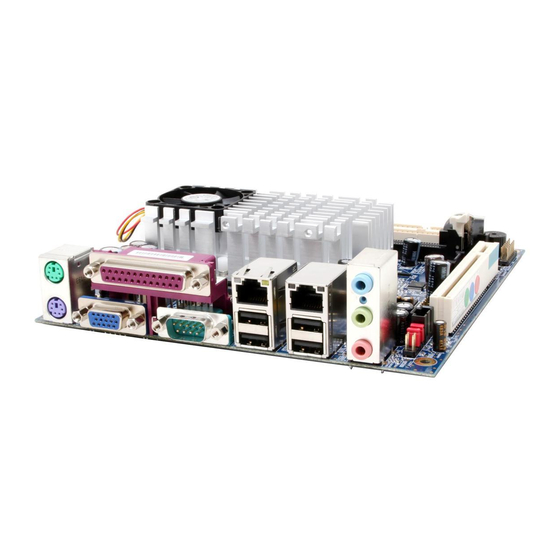
Page 21: Back Panel Ports
Installation ANEL ORTS The back panel has the following ports: Keyboard and Mouse The green 6-pin connector is for a PS/2 mouse. The purple connector is for a PS/2 keyboard. Serial port: COM 1 The green 9-pin COM 1 port is for pointing devices or other serial devices. - Page 22 Chapter 2 RJ45 10/100 LAN and USB 2.0 ports The mainboard provides two standard RJ-45 and four 4- pin Universal Serial Bus (USB) 2.0 ports. These ports allow connection to a Local Area Network (LAN) through a network hub and USB 2.0 devices. LPT port The purple 25-pin port allows you to connect any parallel device.
- Page 23 Installation Audio Port The Line-Out jack is for connecting to external speakers or headphones. The Line-In jack is for connecting to an external audio device such as a CD player, tape player, etc. The Mic jack is for connecting to a microphone.
-
Page 24: Connectors
Chapter 2 ONNECTORS Hard Disk Connectors: IDE1 & IDE2 The mainboard has a 32-bit Enhanced IDE and Ultra DMA 133/100/66 controller that provides PIO mode 0~4, Bus Master, and Ultra DMA 133/100/66 functions. You can connect up to four hard disk drives, CD-ROM and other devices. - Page 25 Installation Case Connector: F_PANEL The F_PANEL pin header allows you to connect the power switch, reset switch, power LED, sleep LED, HDD LED and the case speaker. F_PANEL Signal Signal +5VDUAL +5VDUAL HD_LED -PLED PW_BN RST_SW SPEAK -SLEEP_LED Power Switch (PW_BN) Connect to a 2-pin power button switch.
- Page 26 Chapter 2 Serial ATA Connectors: SATA1 and SATA2 SATA1-2 These next generation connectors support the thin Serial ATA cables for primary internal storage devices. The current Serial ATA interface allows up to 150 MB/s data transfer rate, faster than the standard parallel ATA with 133 MB/s (Ultra DMA). CD-In Connector: CD_In This pin header allows you to receive stereo audio input from sound source such as a CD-ROM...
- Page 27 Installation USB Pin Connector: USB 3-6 The mainboard provides 2 front USB pin headers, allowing up to 4 additional USB2.0 ports up to maximum throughput of 480 Mbps. Connect each 2-port USB cable into the pin header. This port can be used to connect high-speed USB interface peripherals such as USB HDD, digital cameras, MP3 players, printers, modem and the like.
- Page 28 Chapter 2 Serial Port Connector: COM 2/3/4 COM2/3/4 pin headers can be used to attach additional ports for serial mouse or other serial devices. Signal Signal RIN12 RIN32 DOUT22 DOUT32 RIN22 DOUT12 RIN42 XRI2# Digital I/O Connector: DIO General purpose input and output for POS systems. Signal Signal +12V...
- Page 29 Installation Front Panel Audio Connector: F_AUDIO This is an interface for the VIA front panel audio cable that allow convenient connection and control of audio devices. By default, the pins labeled LINE_OUT_R / NEXT_R and the pins LINE_OUT_L / NEXT_L are shorted with jumper caps.
- Page 30 Chapter 2 LVDS/TTL/DVI Connector: JLVDS_DVI This connector works as the interface to multi display devices. An additional daughter card is required for a certain display support. Daughter cards for LVDS and DVI are currently available respectively. JLVDS_DVI Signal Signal FPDVIHS FPDVIVS FPDVIDE SMB2_CK...
- Page 31 Installation Note: ENPVDD: Enable Panel VDD power ENVEE: Enable panel VEE power FPD: Graphic Flat Panel Device signals KBMS Connector: KBMS The mainboard provides a PS2 pin header to attach a PS2 keyboard and mouse. KBMS Signal Signal +5V Dual KB_CLK KB_DATA EKBCLK...
-
Page 32: Jumpers
Chapter 2 UMPERS The mainboard provides jumpers for setting some mainboard functions. This section will explain how to change the settings of the mainboard functions using the jumpers. Clear CMOS Connector: CLEAR_CMOS The onboard CMOS RAM stores system configuration data and has an onboard battery power supply. - Page 33 Installation BIOS Write Protection: WP This jumper allows you to protect from flashing the BIOS. BIOS Write Protection setting: pin1 = /WP & /TBL, pin2 = GND, short 1-2. LVDS Interface Selector: LVDS_DVI LVDS_DVI pin header can be used to switch between 24-bit and Dual 12-bit LVDS interface modes.
-
Page 34: Slots
Chapter 2 LOTS Peripheral Component Interconnect: PCI The PCI slot allows you to insert PCI expansion card. When adding or removing expansion card, first unplug the power supply. Read the documentation for the expansion card if any changes to the system are necessary. -
Page 35: Chapter 3
HAPTER BIOS Setup This chapter gives a detailed explanation of the BIOS setup functions. -
Page 36: Entering Setup
Chapter 3 NTERING ETUP Power on the computer and press <Delete> during the beginning of the boot sequence to enter the BIOS setup menu. If you missed the BIOS setup entry point, you may restart the system and try again. -
Page 37: Control Keys
BIOS Setup ONTROL Keys Description Up Arrow Move to the previous item Down Arrow Move to the next item Left Arrow Move to the item in the left side Right Arrow Move to the item in the right side Enter Select the item Escape Jumps to the Exit menu or returns to the main menu from a... -
Page 38: Navigating The Bios Menus
Chapter 3 BIOS M AVIGATING THE ENUS The main menu displays all the BIOS setup categories. Use the control keys Up/Down arrow keys to select any item/sub-menu. Description of the selected/highlighted category is displayed at the bottom of the screen. An arrow symbol next to a field indicates that a sub-menu is available (see figure below). -
Page 39: Getting Help
BIOS Setup ETTING The BIOS setup program provides a “General Help” screen. You can display this screen from any menu/sub-menu by pressing <F1>. The help screen displays the keys for using and navigating the BIOS setup. Press <Esc> to exit the help screen. -
Page 40: Main Menu
Chapter 3 Phoenix - AwardBIOS CMOS Setup Utility Standard CMOS Features Frequency / Voltage Control Advanced BIOS Features Load Fail-Safe Defaults Advanced Chipset Features Load Optimized Defaults Integrated Peripherals Set Supervisor Password Power Management Setup Set User Password PnP / PCI Configurations Save &... - Page 41 BIOS Setup PC Health Status This menu shows the PC health status. Frequency/Voltage Control Use this menu to set the system frequency and voltage control. Load Fail-Safe Defaults Use this menu option to load the BIOS default settings for minimal and stable system operations.
-
Page 42: Standard Cmos Features
Chapter 3 CMOS F TANDARD EATURES Phoenix - AwardBIOS CMOS Setup Utility Standard CMOS Features Date (mm:dd:yy) Tue, 21 2004 Item Help Time (hh:mm:ss) 20 20 20 Menu Level IDE Channel 0 Master [None] Change the day, month, year IDE Channel 0 Slave [QUANTUM FIREBALLP AS] and century IDE Channel 1 Master... -
Page 43: Ide Drives
BIOS Setup IDE D RIVES Phoenix - AwardBIOS CMOS Setup Utility IDE Channel 0 Master IDE HDD Auto-Detection [Press Enter] Item Help Menu Level IDE Channel 0 Master [Auto] Access Mode [Auto] To auto-detect the HDD's size, head... on this channel Capacity 0 MB Cylinder... -
Page 44: Advanced Bios Features
Chapter 3 BIOS F DVANCED EATURES Phoenix - AwardBIOS CMOS Setup Utility Advanced BIOS Features Hard Disk Boot Priority [Press Enter] Item Help Virus Warning [Disabled] CPU Internal Cache [Enabled] Menu Level Processor Number Feature [Enabled] Quick Power On Self Test [Enabled] Select Hard Disk Boot First Boot Device... - Page 45 BIOS Setup Quick Power On Self-Test Shortens Power On Self-Test (POST) cycle to enable shorter boot up time. Setting Description Enabled Shorten Power On Self Test (POST) cycle and bootup time Disabled Standard Power On Self Test (POST) First/Second/Third Boot Device Set the boot device sequence as BIOS attempts to load the disk operating system.
- Page 46 Chapter 3 Typematic Rate (Chars/Sec) This item sets the rate (characters/second) at which the system retrieves a signal from a depressed key. Settings: [6, 8, 10, 12, 15, 20, 24, 30] Typematic Delay (Msec) This item sets the delay between when the key was first pressed and when the system begins to repeat the signal from the depressed key.
-
Page 47: Hard Disk Boot Priority
BIOS Setup RIORITY Phoenix - AwardBIOS CMOS Setup Utility Hard Disk Boot Priority Item Help Pri. Master : Pri. Slave Menu Level Sec. Master : Sec. Slave : Use < > or < > to USBHDD0 select a device, then USBHDD1 press <... -
Page 48: Advanced Chipset Features
Chapter 3 DVANCED HIPSET EATURES Phoenix - AwardBIOS CMOS Setup Utility Advanced Chipset Features [PCI Slot] Display Card Priority Item Help [Press Enter] AGP & P2P Bridge Control [Press Enter] Menu Level CPU & PCI Bus Control [CRT] Select Display Device If there are display cards on [1024x768 : 1 :On] Panel Type... - Page 49 BIOS Setup Panel Type This setting refers to the native resolution of the display being used with the system. Key in a HEX number. Settings: [ 640x480 : 1 :On, 800x600 : 1 :On, 1024x768 : 1 :On, 1280x768 : 1 :On, 1280x1024 : 2 :On, 1400x1050 : 2 :On, 1600x1200 : 2 :On,...
-
Page 50: Agp & P2P Bridge Control
Chapter 3 AGP & P2P B RIDGE ONTROL Phoenix - AwardBIOS CMOS Setup Utility AGP & P2P Bridge Control AGP Aperture Size [128M] Item Help AGP 2.0 Mode [4x] Menu Level VGA Share Memory Size [64M] Direct Frame Buffer [Enabled] : Move Enter: Select +/-/PU/PD: Value... -
Page 51: Cpu & Pci Bus Control
BIOS Setup CPU & PCI B ONTROL Phoenix - AwardBIOS CMOS Setup Utility CPU & PCI Bus Control VLink mode selection [Mode 1] Item Help Menu Level : Move Enter: Select +/-/PU/PD: Value F10: Save ESC: Exit F1: General Help F5: Previous Values F6: Fail-Safe Defaults F7: Optimized Defaults... -
Page 52: Integrated Peripherals
Chapter 3 NTEGRATED ERIPHERALS Phoenix - AwardBIOS CMOS Setup Utility Integrated Peripherals SuperIO Device [Press Enter] Item Help Menu Level Onboard IDE Channel 1 [Enabled] Onboard IDE Channel 2 [Enabled] IDE Prefetch Mode [Enabled] OnChip SATA [Enabled] SATA Mode [RAID] AC97 Audio [Auto] VIA OnChip LAN... - Page 53 BIOS Setup SATA Mode Serial ATA is the latest generation of the ATA interface. Serial ATA hard drives deliver transfer speeds of up to 150MB/sec. Setting Description Supports two SATA plus two PATA hard disk drives RAID Only SATA supports RAID AC’97 Audio Auto allows the mainboard to detect whether an audio device is used.
- Page 54 Chapter 3 OnChip USB Controller Settings: [All Disabled, All Enabled, 1&2 USB Port, 2&3 USB Port, 1&3 USB Port, 1 USB Port, 2 USB Port, 3 USB Port] OnChip EHCI Controller Settings: [Enabled, Disabled] USB Emulation Set this field to choose the USB emulation. When set to “OFF “, do not support any USB device on DOS.
-
Page 55: Super Io Device
BIOS Setup IO D UPER EVICE Phoenix - AwardBIOS CMOS Setup Utility SuperIO Device Onboard Serial Port 1 [3F8/IRQ4] Item Help Onboard Serial Port 2 [2F8/IRQ3] Menu Level UART Mode Select [Normal] RxD, TxD Active [Hi,Hi] IR Transmission Delay [Disabled] UR2 Duplex Mode [Half] Use IR Pins... - Page 56 Chapter 3 Use IR Pins Settings: [RxD2.TxD2, IR-Rx2Tx2] Onboard Parallel Settings: [Disabled, 378/IRQ7, 278/IRQ5, 3BC/IRQ7] Parallel Port Mode Settings: [SPP, EPP, ECP, ECP+EPP, Normal] EPP Mode Select Settings: [EPP1.9, EPP1.7] ECP Mode Use DMA Settings: [1, 3] UART 3/4 Settings: [Disabled, 3F8, 2F8, 3E8, 2E8] UART 3/4 Use IRQ Settings: [IRQ3, IRQ4, IRQ5, IRQ10, IRQ11]...
-
Page 57: Power Management Setup
BIOS Setup OWER ANAGEMENT ETUP Phoenix - AwardBIOS CMOS Setup Utility Power Management Setup ACPI Suspend Type [S1(POS)] Item Help HDD Power Down [Disabled] Menu Level Power Management Timer [Disabled] Video Off Option [Suspend -> Off] This item allows you to select how the BIOS Power Off by PWRBTN [Instant-Off]... - Page 58 Chapter 3 Power Management Timer Set the idle time before system enters power saving mode. ACPI OS such as Windows XP will override this option. Settings: [Disabled, 1/2/4/6/8/10/20/30/40 (minutes), 1 (hour)] Video Off Option Select whether or not to turn off the screen when system enters power saving mode, ACPI OS such as Windows XP will override this option.
-
Page 59: Peripheral Activities
BIOS Setup ERIPHERAL CTIVITIES Phoenix - AwardBIOS CMOS Setup Utility Peripherals Activities VGA Event [OFF] Item Help LPT & COM Event [COM] HDD Event [ON] Menu Level PCI Master Event [OFF] Decide whether or not PS2KB Wakeup Select [Hot Key] the power management PS2MS Wakeup from S3/S4/S5 [Disabled]... - Page 60 Chapter 3 PS2KB Wakeup Select When selecting “Password”, press <Page Up> or <Page Down> to change password. The maximum number of characters is eight. “PS2MS Wakeup from S3/S4/S5” and “PS2KB Wakeup from S3/S4/S5” will be disabled while changing the password. Settings: [Hot Key, Password] PS2MS Wakeup from S3/S4/S5 Enables any mouse activity to restore the system from the power saving...
- Page 61 BIOS Setup RTC Alarm Resume Sets a scheduled time and/or date to automatically power on the system. Settings: [Disabled, Enabled] Date (of Month) The field specifies the date for “RTC Alarm Resume”. Resume Time (hh:mm:ss) The field specifies the time for “RTC Alarm Resume”.
-
Page 62: Irqs Activities
Chapter 3 CTIVITIES Phoenix - AwardBIOS CMOS Setup Utility IRQs Activities Primary INTR [ON] Item Help IRQ3 (COM 2) [Disabled] Menu Level IRQ4 (COM 1) [Enabled] IRQ5 (COM 3) [Disabled] If you choose Disabled, the IRQ6 (Reserved) [Disabled] power management unit will IRQ7 (LPT ) [Disabled] IRQ8 (RTC Alarm) -
Page 63: Pnp/Pci Configurations
BIOS Setup PNP/PCI C ONFIGURATIONS Phoenix - AwardBIOS CMOS Setup Utility PnP / PCI Configurations PNP OS Installed [No] Item Help Reset Configuration Data [Disabled] Menu Level Resources Controlled By [Auto(ESCD)] Select Yes if you are using a IRQ Resources Press Enter Plug and Play capable Assign IRQ For VGA... - Page 64 Chapter 3 Reset Configuration Data This field should usually be left “Disabled”. Setting Description Enabled Resets the ESCD (Extended System Configuration Data) after exiting BIOS Setup if a newly installed PCI card or the system configuration prevents the operating system from loading Disabled Default setting...
-
Page 65: Irq Resources
BIOS Setup IRQ R ESOURCES Phoenix - AwardBIOS CMOS Setup Utility IRQ Resources IRQ-3 assigned to [PCI Device] Item Help IRQ-4 assigned to [PCI Device] Menu Level IRQ-5 assigned to [PCI Device] IRQ-7 assigned to [PCI Device] Legacy ISA for devices IRQ-9 assigned to [PCI Device] compliant with the original PC... -
Page 66: Pc Health Status
Chapter 3 PC H EALTH TATUS Phoenix - AwardBIOS CMOS Setup Utility PC Health Status CPU Temp. High Limit [Disabled] Item Help [0 degC] CPU Temp. Tolerance Menu Level Chassis Temp. High Limit [Disabled] Chassis Temp. Tolerance [0 degC] CPU Temperature Chassis Temperature CPU FAN Speed Chassis FAN Speed... -
Page 67: Frequency / Voltage Control
BIOS Setup REQUENCY OLTAGE ONTROL Phoenix - AwardBIOS CMOS Setup Utility Frequency / Voltage Control DRAM Clock [By SPD] Item Help DRAM Timing [Auto By SPD] Menu Level SDRAM CAS Latency Bank Interleave Disabled Precharge to Active(Trp) Active to Precharge(Tras) Active to CMD(Trcd) REF to ACT/REF to REF(Trfc ACT(0) to ACT(1) (TRRD) - Page 68 Chapter 3 SDRAM CAS Latency This item is for setting the speed it takes for the memory module to complete a command. Generally, a lower setting will improve the performance of your system. However, if your system becomes less stable, you should change it to a higher setting.
- Page 69 BIOS Setup REF to ACT / REF (Trfc) This field is only available when “DRAM Timing” is set to “Manual”. Settings: [12T, 13T, 14T, 15T] ACT(0) to ACT(1) (TRRD) This field is only available when “DRAM Timing” is set to “Manual”. Settings: [2T, 3T] DRAM Command Rate This field is for setting how fast the memory controller sends out commands.
-
Page 70: Load Fail-Safe Defaults
Chapter 3 EFAULTS Phoenix - AwardBIOS CMOS Setup Utility Standard CMOS Features Frequency / Voltage Control Advanced BIOS Features Load Fail-Safe Defaults Advanced Chipset Features Load Optimized Defaults Integrated Peripherals Set Supervisor Password Power Management Setup Set User Password PnP / PCI Configurations Load Fail-Safe Defaults (Y/N)? Save &... -
Page 71: Load Optimized Defaults
BIOS Setup PTIMIZED EFAULTS Phoenix - AwardBIOS CMOS Setup Utility Standard CMOS Features Frequency / Voltage Control Advanced BIOS Features Load Fail-Safe Defaults Advanced Chipset Features Load Optimized Defaults Integrated Peripherals Set Supervisor Password Power Management Setup Set User Password PnP / PCI Configurations Load Optimized Defaults (Y/N)? Save &... -
Page 72: Set Supervisor / User Password
Chapter 3 UPERVISOR ASSWORD Phoenix - AwardBIOS CMOS Setup Utility Standard CMOS Features Frequency / Voltage Control Advanced BIOS Features Load Fail-Safe Defaults Advanced Chipset Features Load Optimized Defaults Integrated Peripherals Set Supervisor Password Power Management Setup Set User Password PnP / PCI Configurations Enter Password: Save &... - Page 73 BIOS Setup To disable the password, press <Enter> when prompted to enter a new password. A message will show up to confirm disabling the password. To cancel the process press <Esc>. Additionally, when a password is enabled, the BIOS can be set to request the password each time the system is booted.
-
Page 74: Save & Exit Setup
Chapter 3 & E ETUP Phoenix - AwardBIOS CMOS Setup Utility Standard CMOS Features Frequency / Voltage Control Advanced BIOS Features Load Fail-Safe Defaults Advanced Chipset Features Load Optimized Defaults Integrated Peripherals Set Supervisor Password Power Management Setup Set User Password PnP / PCI Configurations SAVE to CMOS &... -
Page 75: Exit Without Saving
BIOS Setup ITHOUT AVING Phoenix - AwardBIOS CMOS Setup Utility Standard CMOS Features Frequency / Voltage Control Advanced BIOS Features Load Fail-Safe Defaults Advanced Chipset Features Load Optimized Defaults Integrated Peripherals Set Supervisor Password Power Management Setup Set User Password PnP / PCI Configurations Quit Without Saving (Y/N)? Save &... -
Page 76: Chapter 4
HAPTER Driver Installation This chapter gives you brief descriptions of each mainboard driver and application. You must install the VIA chipset drivers first before installing other drivers such as audio or VGA drivers. The applications will only function correctly if the necessary drivers are already installed. -
Page 77: Driver Utilities
Driver Installation RIVER TILITIES Getting Started The mainboard includes a Driver Utilities CD that contains the driver utilities and software for enhancing the performance of the mainboard. If the CD is missing from the retail box, please contact the local dealer for the CD. Note: The driver utilities and software are updated from time to time. - Page 78 Chapter 4 Running the Driver Utilities CD To start using the CD, insert the CD into the CD-ROM or DVD-ROM drive. The CD should run automatically after closing the CD-ROM or DVD-ROM drive. The driver utilities and software menu screen should then appear on the screen.
-
Page 79: Cd Content
Driver Installation CD C ONTENT VIA 4in1 Drivers: Contains VIA ATAPI Vendor Support Driver (enables the performance enhancing bus mastering functions on ATA-capable Hard Disk Drives and ensures IDE device compatibility), AGP VxD Driver (provides service routines to your VGA driver and interface directly to hardware, providing fast graphical access), IRQ Routing Miniport Driver (sets the system's PCI IRQ routing sequence) and VIA INF Driver (enables the VIA Power Management function).
Need help?
Do you have a question about the EPIA-EK10000G - VIA Motherboard - Mini ITX and is the answer not in the manual?
Questions and answers