Table of Contents
Advertisement
Quick Links
Download this manual
See also:
Operating Manual
Advertisement
Table of Contents

Subscribe to Our Youtube Channel
Related Manuals for VIA Technologies EPIA-N800


Summary of Contents for VIA Technologies EPIA-N800
- Page 1 EPIA-N800 Nano-ITX Mainboard Revision 1.04 104-08182010-1752...
-
Page 2: Regulatory Compliance
PS/2 is a registered trademark of IBM Corporation. Disclaimer No license is granted, implied or otherwise, under any patent or patent rights of VIA Technologies. VIA Technologies makes no warranties, implied or otherwise, in regard to this document and to the products described in this document. The information provided in this document is believed to be accurate and reliable as of the publication date of this document. -
Page 3: Safety Precautions
Safety Precautions Do’s Always read the safety instructions carefully. Keep this User's Manual for future reference. All cautions and warnings on the equipment should be noted. Keep this equipment away from humidity. Lay this equipment on a reliable flat surface before setting it up. -
Page 4: Box Contents
Box Contents 1 x EPIA-N800 Nano-ITX mainboard 1 x SATA cable 1 x SATA power cable 1 x USB cable 1 x DC-In cable 1 x Driver utility CD... -
Page 5: Table Of Contents
ABLE OF ONTENTS 1 Product Overview....................1 Key Components ....................2 VIA Nano 1.3+ GHz Processor ..............2 VIA VX800 All-in-one System Processor..........2 Mainboard Specifications ................3 EPIA-N800 Layout ....................4 Top View ......................4 Bottom View..................... 5 Side View......................5 2 Onboard Connectors, Slots and Pin Headers........ - Page 6 Inverter power selector: IVDDSEL............22 Power mode selector: AT/ATX..............23 SATA DOM power selector: SATA_DOM1 ........23 COM1 serial mode selector: J1..............24 COM2 power selector: J3 ................25 4 Back Panel Ports....................26 D-sub 15 display port: VGA ..............27 RS-232/422/485 port: COM1 ..............27 USB 2.0 ports: USB_0/1................27 Gigabit Ethernet RJ45 port: LAN............27 5 BIOS Setup......................28 Entering the BIOS Setup Menu ..............29...
- Page 7 VIA Wireless LAN Support...............44 Super IO Device ....................45 Onboard Serial Port 1 ................45 Onboard Serial Port 2 ................45 Onboard Serial Port 3 ................45 Onboard Serial Port 4 ................45 WatchDog Support ..................45 WatchDog Timer Select................45 WatchDog Count Value ................45 VIA OnChip IDE Device .................46...
- Page 8 IDE Prefetch Mode ..................46 CF Card UDMA66 ..................46 IDE DMA Transfer Access ................46 Secondary Master PIO ................46 Secondary Slave PIO...................46 Secondary Master UDMA ................46 Secondary Slave UDMA................46 USB Device Setting ...................47 USB 1.0 Controller ..................47 USB 2.0 Controller ..................47 USB Operation Mode ................47 USB Keyboard Function................47 USB Mouse Function .................47 USB Storage Function................48...
- Page 9 Maximum Payload Size................55 IRQ Resources .....................56 PC Health Status....................57 Frequency/Voltage Control.................58 DRAM Frequency ..................58 DRAM Channel Mode ................58 DDR CAS Latency Control ...............58 DDR Burst Length..................58 DDR 1T Command Rate ................58 DRDY Table .....................58 ODT........................58 Spread Spectrum..................59 Load Optimized Defaults................60 Set Supervisor/User Password ..............61 Set Supervisor....................61 User Password ....................61...
-
Page 10: Product Overview
Product Overview... -
Page 11: Key Components
OMPONENTS VIA Nano 1.3+ GHz Processor Due to its ultra cool, ultra quiet, and reliable performance, the VIA Nano 1.3+ GHz NanoBGA2 processor is a perfect fit for compact embedded systems that need a good performance per watt ratio. -
Page 12: Mainboard Specifications
Two SATA power connectors One CF Type 1 socket VIA VT1708S High Definition Audio Codec Audio One VIA VT6130 PCIe Gigabit Ethernet controller One Audio pin connector for Line-out, Line-in and Mic-in Onboard I/O One dual-channel LVDS connector (5V/3V) Connectors... -
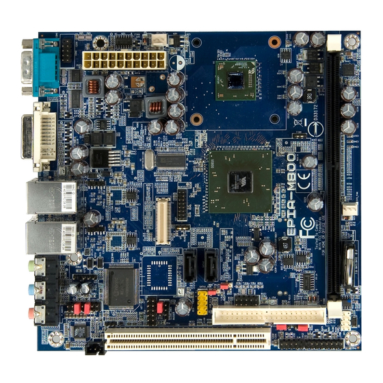
Page 13: Epia-N800 Layout
EPIA-N800 L AYOUT Top View Symbol Page Symbol Page AT/ATX BAT1 JSP1 CLEAR_CMOS KB/MS COM2 LVDS COM3 PVDD_SEL COM4 S_POWER1 CPU_FAN SATA_DOM1 DC12VI SATA1 SATA2 F_AUDIO1 FPANEL SMBUS INVERTER SYS_FAN IVDDSEL USB_2/3... -
Page 14: Bottom View
Bottom View Symbol Page Symbol Page DDR2_SODIMM S_POWER2 MINIPCI Side View Symbol Page Symbol Page GigaLAN USB 2.0 RS-232/422/485... -
Page 15: Onboard Connectors, Slots And Pin Headers
Onboard Connectors, Slots and Pin Headers This chapter provides you with information about hardware installation procedures. It is recommended to use a grounded wrist strap before handling computer components. Electrostatic discharge (ESD) can damage some components. -
Page 16: Top Side Connectors
ONNECTORS DC-In power connector: DC12VI Power is delivered to the mainboard through a 4-pin 12V power connector. Signal Ground Ground +12 VDC +12 VDC CMOS Battery: BAT1 The mainboard comes with external CMOS battery connector. This 2-pin connector used to connect the external cable battery for CMOS. -
Page 17: Front Panel Pin Header: Fpanel
Front Panel pin header: FPANEL This pin header allows you to connect the power switch, reset switch, power LED, HDD LED, AND case speaker. Signal Signal +PWR_LED +HD_LED +PWR_LED -HD_LED -PWR_LED PW_BN SPEAK+ —- RST_SW SPEAK- Fan connector: CPU_FAN, SYS_FAN The fans run on +12V. -
Page 18: Temperature Sensor: Sen
Temperature sensor: SEN The mainboard comes with a system temperature sensor pin header. Connect a temperature sensor to the 3-pin header to enable the BIOS to monitor the system temperature. The recommended sensor model is NPN sensor MOS, 2N3904. Signal REMOTE1+ REMOTE1+ REMOTE1-... -
Page 19: Smbus Pin Header: Smbus
SMBus pin header: SMBUS This pin header allows connection to SMBus devices. Signal SMBCK SMBDT Ground Digital I/O pin header: DIO This pin header allows connection to DIO devices. Signal Signal 5V_DIO 12V_DIO GPO_21 GPI_44 GPO_22 GPI_45 GPO_32 GPI_46 GPO_33 GPI_47 Ground Ground... -
Page 20: Front Audio Pin Header: F_Audio1
Front Audio pin header: F_AUDIO1 This pin header allows you to connect a front audio to the mainboard. Signal Signal SPDIF_OUT Ground —- LINEOUT_R LINEOUT_L LINEIN_R LINEIN_L MIC1_RE_R MIC1_RE_L —- Ground Ground Keyboard and mouse: KB/MS This pin header allows you to connect PS/2 keyboard and mouse ports. -
Page 21: Serial Port: Com2, Com3, Com4
Serial port: COM2, COM3, COM4 The mainboard has three COM pin headers. These three pin headers provide additional RS-232 support. Additionally, COM2 can change power modes between +5V and +12V. See page 25 for details. Signal Signal SOUT —- USB pin header: USB_2/3 The USB pin header is for adding up to two additional USB 2.0 ports. -
Page 22: Sata Power: S_Power1
SATA power: S_POWER1 The mainboard has a 4-pin SATA power connector on the top side. Plug the SATA power cable into the SATA power connector. Make sure the power plug pins are aligned and inserted in the proper orientation. Signal Ground Ground SATA connector: SATA1, SATA2... -
Page 23: Compactflash Type 1: Cf
CompactFlash Type 1: CF The mainboard provides support for one CF Type 1 device. LVDS Panel connector: PANEL The dual-channel LVDS connector allows you to connect the panel’s LVDS cable directly to support LVDS panel. Signal Signal -A4_L PVDD A4_L PVDD Ground Ground... -
Page 24: Lvds Backlight Connector: Inverter
LVDS backlight connector: INVERTER The inverter connector allows you to connect a backlight control for the LVDS panel. Signal BAKLITE PWM_OUT BAKLITE SMBUS_OUT Ground Ground... -
Page 25: Bottom Side Connector
OTTOM ONNECTOR Mini PCI slot: MINIPCI The mainboard has an onboard Mini PCI slot for using +3.3V SATA power: S_POWER2 The mainboard also has a 4-pin SATA power connector on the bottom side. Plug the SATA power cable into the SATA power connector. -
Page 26: Memory Module Installation
Memory Module Installation Memory Slot: DDR2_SODIMM The VIA EPIA-N800 Pico-ITX mainboard has one 200-SODIMM slot for DDR2 667/533 SDRAM memory modules and supports memory sizes up to 2 GB. Available DDR2 SDRAM Configuration Refer to the table below for available DDR2 SDRAM configurations on the mainboard. -
Page 27: Installing The Memory
Installing the memory Step 1 Locate the SODIMM slot in the mainboard and align the notch on the SODIMM with the memory slot. Step 2 Insert the SODIMM module at a 45 degree angle. Then push the SODIMM down until it snaps into the locking mechanism. -
Page 29: Onboard Jumpers
Onboard Jumpers... -
Page 30: Jumpers
UMPERS Clear CMOS jumper: CLEAR_CMOS The onboard CMOS RAM stores system configuration data and has an onboard battery power supply. To reset the CMOS settings, set the jumper on pins 2 and 3 while the system is off. Return the jumper to pins 1 and 2 afterwards. -
Page 31: Panel Power Selector: Pvdd_Sel
Panel power selector: PVDD_SEL This jumper determines the input voltage for the LCD connector. The default setting is +3.3V. Setting +3.3V Inverter power selector: IVDDSEL This jumper determines the input voltage for the LCD backlight inverter. The default setting is +5V. Setting +12V... -
Page 32: Power Mode Selector: At/Atx
Power mode selector: AT/ATX This jumper sets the mainboard to either the AT or ATX power profile. The default mode is ATX. Setting SATA DOM power selector: SATA_DOM1 This jumper enables or disables the 7 power pin on SATA1. The default setting is “Normal”. -
Page 33: Com1 Serial Mode Selector: J1
COM1 serial mode selector: J1 This jumper sets the serial mode for COM1. Supported serial standards are RS-232, RS-422, and RS-485. Setting Cap pairs RS-232 RS-422 RS-485... -
Page 34: Com2 Power Selector: J3
COM2 power selector: J3 This jumper sets the power profile for COM2. The default setting is +5V. Setting +12V... -
Page 35: Back Panel Ports
Back Panel Ports... -
Page 36: D-Sub 15 Display Port: Vga
232, RS-422, or RS-485 serial standards. See page 24 for details on jumper settings. USB 2.0 ports: USB_0/1 Two standard USB 2.0 ports are provided on the back panel. Gigabit Ethernet RJ45 port: LAN The mainboard provides one Gigabit Ethernet port controlled by the onboard VIA VT6130 PCIe Gigabit Ethernet controller. -
Page 37: Bios Setup
BIOS Setup This chapter gives a detailed explanation of the BIOS setup functions. -
Page 38: Entering The Bios Setup Menu
BIOS S NTERING THE ETUP Power on the computer and press <Delete> during the beginning of the boot sequence to enter the BIOS setup menu. If you missed the BIOS setup entry point, restart the system and try again. ONTROL Keys Description Move to the previous item... -
Page 39: Getting Help
ETTING The BIOS setup program provides a “General Help” screen. You can display this screen from any menu/sub-menu by pressing <F1>. The help screen displays the keys for using and navigating the BIOS setup. Press <Esc> to exit the help screen. -
Page 40: Main Menu
The Main Menu contains twelve setup functions and two exit choices. Use arrow keys to select the items and press <Enter> to accept or enter Sub-menu. Standard CMOS Features Use this menu to set basic system configurations. Advanced BIOS Features Use this menu to set the advanced features available on your system. -
Page 41: Pc Health Status
PC Health Status This menu shows the PC health status. Frequency/Voltage Control Use this menu to set the system frequency and voltage control. Load Optimized Defaults Use this menu option to load BIOS default settings for optimal and high performance system operations. Set Supervisor Password Use this menu option to set the BIOS supervisor password. -
Page 42: Standard Cmos Features
CMOS F TANDARD EATURES Date The date format is [Day, Month Date, Year] Time The time format is [Hour : Minute : Second] Video Settings: [EGA/VGA, CGA 40, CGA 80, MONO] Halt On Set the system’s response to specific boot errors. Below is a table that details the possible settings. -
Page 43: Advanced Bios Features
BIOS F DVANCED EATURES Virus Warning Allows you to choose the VIRUS warning feature for IDE Hard Disk boot sector protection. Settings Description Enabled Turns on hard disk boot sector virus protection Disabled Turns off hard disk boot sector virus protection Note: If this function is enabled and someone attempt to write data into this area, BIOS will show a warning message on the screen... -
Page 44: Quick Power On Self-Test
Quick Power On Self-Test Shortens Power On Self-Test (POST) cycle to enable shorter boot up time. Settings Description Disabled Standard Power On Self Test (POST) Enabled Shorten Power On Self Test (POST) cycle and boot up time First/Second/Third Boot Device Set the boot device sequence as BIOS attempts to load the disk operating system. -
Page 45: Typematic Rate (Chars/Sec)
Typematic Rate (Chars/Sec) This item sets the rate (characters/second) at which the system retrieves a signal from a depressed key. Settings: [6, 8, 10, 12, 15, 20, 24, 30] Typematic Delay (Msec) This item sets the delay between, when the key was first pressed and when the system begins to repeat the signal from the depressed key. -
Page 46: Full Screen Logo Show
Full Screen Logo Show Show full screen logo during BIOS boot up process. Settings: [Disabled, Enabled] Summary Screen Show Show summary screen. Settings: [Disabled, Enabled]... -
Page 47: Cpu Features
CPU F EATURES Thermal Management This item sets CPU’s thermal control rule to protect CPU from overheat. Settings Description Dynamic Ratio and VID Thermal Monitor Disabled... -
Page 48: Hard Disk Boot Priority
RIORITY This is for setting the priority of the hard disk boot order when the “Hard Disk” option is selected in the “[First/Second/Third] Boot Device” menu item. -
Page 49: Advanced Chipset Features
DVANCED HIPSET EATURES Caution: The Advanced Chipset Features menu is used for optimizing the chipset functions. Do not change these settings unless you are familiar with the chipset. Memory Hole Settings: [Disabled, 15M – 16M] System BIOS Cacheable Settings: [Disabled, Enabled] Video RAM Cacheable Settings: [Disabled, Enabled] AGP Fast Write... -
Page 50: Panel Type
Panel Type Key in a HEX number. Settings: [Min = 0000, Max = 000F] Resolution Code 640 x 480 800 x 600 1024 x 768 1280 x 768 1280 x 1024 1400 x 1050 1440 x 900 1280 x 800 800 x 480 1024 x 600 1366 x 768... -
Page 51: Internal Vga Control
VGA C NTERNAL ONTROL AGP 3.0 Calibration Cycle Settings: [Disabled, Enabled] VGA Share Memory Size This setting allows you to select the amount of system memory that is allocated to the integrated graphics processor. Settings: [Disabled, 64M, 128M, 256M] Direct Frame Buffer Settings: [Disabled, Enabled] Outport Port Settings: [DI0, DI1]... -
Page 52: Cpu & Pci Bus Control
CPU & PCI B ONTROL PCI Master 0 WS Write Settings: [Enabled, Disabled] PCI Delay Transaction Settings: [Disabled, Enabled] VIA PWR Management Settings: [Disabled, Enabled]... -
Page 53: Integrated Peripherals
Settings: [Disabled, Enabled] IDE HDD Block Mode Settings: [Disabled, Enabled] SATA Controller Settings: [Disabled, Enabled] SATA Controller Mode Settings: [IDE, RAID] Azalia HDA Controller Settings: [Auto, Disabled] Onboard LAN Boot ROM Settings: [Enabled, Disabled] VIA Wireless LAN Support Settings: [Enabled, Disabled]... -
Page 54: Super Io Device
IO D UPER EVICE Onboard Serial Port 1 Settings: [Disabled, 3F8/IRQ4, 2F8/IRQ4, 3E8/IRQ4, 2E8/IRQ4] Onboard Serial Port 2 Settings: [Disabled, 3F8/IRQ4, 2F8/IRQ4, 3E8/IRQ4, 2E8/IRQ4] Onboard Serial Port 3 Settings: [Disabled, 3F8/IRQ4, 2F8/IRQ4, 3E8/IRQ4, 2E8/IRQ4] Onboard Serial Port 4 Settings: [Disabled, 3F8/IRQ4, 2F8/IRQ4, 3E8/IRQ4, 2E8/IRQ4] WatchDog Support Settings: [Enabled, Disabled] WatchDog Timer Select... -
Page 55: Via Onchip Ide Device
VIA O IDE D EVICE IDE Prefetch Mode Settings: [Disabled, Enabled] CF Card UDMA66 Settings: [Disabled, Enabled] IDE DMA Transfer Access Settings: [Disabled, Enabled] Secondary Master PIO Settings: [Auto, Mode 0, Mode 1, Mode 2, Mode 3, Mode 4] Secondary Slave PIO... -
Page 56: Usb Device Setting
USB D EVICE ETTING USB 1.0 Controller Enable or disable Universal Host Controller Interface for Universal Serial Bus. Settings: [Disabled, Enabled] USB 2.0 Controller Enable or disable Enhanced Host Controller Interface for Universal Serial Bus. Settings: [Disabled, Enabled] USB Operation Mode Auto decide USB device operation mode. -
Page 57: Usb Storage Function
USB Storage Function Enable or disable Legacy support of USB Mass Storage. Settings: [Disabled, Enabled]... -
Page 58: Power Management Setup
OWER ANAGEMENT ETUP ACPI Suspend Type Settings Description S1(POS) S1/Power On Suspend (POS) is a low power state. In this state, no system context (CPU or chipset) is lost and hardware maintains all system contexts. S3(STR) S3/Suspend To RAM (STR) is a power-down state. In this state, power is supplied only to essential components such as main memory and wakeup-capable devices. -
Page 59: Suspend Mode
Suspend Mode Sets the length of time for a period of inactivity before entering suspend mode. Settings: [Disable, 1 Min, 2 Min, 4 Min, 6 Min, 8 Min, 10 Min, 20 Min, 30 Min, 40 Min, 1 Hour] Video Off Option Select whether or not to turn off the screen when system enters power saving mode, ACPI OS such as Windows XP will override this option. -
Page 60: Ac Loss Auto Restart
AC Loss Auto Restart The field defines how the system will respond after an AC power loss during system operation. Settings Description Keeps the system in an off state until the power button is pressed Restarts the system when the power is back Former-Sts Former-Sts... -
Page 61: Wakeup Event Detect
AKEUP VENT ETECT PS2KB Wakeup Select When selecting “Password”, press <Page Up> or <Page Down> to change password. The maximum number of characters is eight. “PS2MS Wakeup from S3/S4/S5” and “PS2KB Wakeup from S3/S4/S5” will be disabled while changing the password. Settings: [Hot Key, Password] PS2KB Wakeup Key Select Sets a Hot Key to restore the system from the power saving mode... -
Page 62: Ps2 Mouse Power On
PS2 Mouse Power On Settings: [Disabled, Enabled] USB Resume from S3 Settings: [Disabled, Enabled] Wakeup On GPI Settings: [Disabled, Enabled] PowerOn by PCI Card Enables activity detected from any PCI card to power up the system or resume from a suspended state. Such PCI cards include LAN, onboard USB ports, etc. -
Page 63: Pnp/Pci Configurations
P/PCI C ONFIGURATIONS Note: This section covers some very technical items and it is strongly recommended to leave the default settings as is unless you are an experienced user. Init Display First Settings: [PCI Slot, Onboard, AGP, PCIEx] PNP OS Installed Settings Description BIOS will initialize all the PnP cards... -
Page 64: Resources Controlled By
Resources Controlled By Enable the BIOS to automatically configure all the Plug-and-Play compatible devices. Settings Description Auto(ESCD) BIOS will automatically assign IRQ, DMA and memory base address fields Manual Unlocks “IRQ Resources” for manual configuration PCI/VGA Palette Snoop Some non-standard VGA display cards may not show colors properly. -
Page 65: Irq Resources
IRQ R ESOURCES IRQ Resources list IRQ 7/9/10/11/12/14/15 for users to set each IRQ a type depending on the type of device using the IRQ. Settings: For Plug-and-Play compatible devices designed for PCI PCI Device bus architecture The IRQ will be reserved for further requests Reserved... -
Page 66: Pc Health Status
PC H EALTH TATUS The PC Health Status displays the current status of all of the monitored hardware devices/components such as CPU voltages, temperatures and fan speeds. -
Page 67: Dram Frequency
REQUENCY OLTAGE ONTROL DRAM Frequency Settings: [DDR2-400, DDR2-533, DDR-667, SPD] DRAM Channel Mode Settings: [Channel A, Channel A&B, Channel A&C] DDR CAS Latency Control Settings: [2T, 3T, 4T, 5T, 6T, SPD] DDR Burst Length Settings: [4, 8, SPD] DDR 1T Command Rate Settings: [Disabled, Enabled] DRDY Table Settings: [Slowest, Optimize]... -
Page 68: Spread Spectrum
Spread Spectrum When the mainboard's clock generator pulses, the extreme values (spikes) of the pulses create EMI (Electromagnetic Interference). The Spread Spectrum function reduces the EMI generated by modulating the pulses so that the spikes of the pulses are reduced to flatter curves. -
Page 69: Load Optimized Defaults
PTIMIZED EFAULTS This option is for restoring all the default optimized BIOS settings. The default optimized values are set by the mainboard manufacturer to provide a stable system with optimized performance. Entering “Y” and press <Enter> to load the default optimized BIOS values. -
Page 70: Set Supervisor/User Password
UPERVISOR ASSWORD Set Supervisor User Password This option is for setting a password for entering BIOS Setup. When a password has been set, a password prompt will be displayed whenever BIOS Setup is run. This prevents an unauthorized person from changing any part of your system configuration. - Page 71 There are two types of passwords you can set. A supervisor password and a user password. When a supervisor password is used, the BIOS Setup program can be accessed and the BIOS settings can be changed. When a user password is used, the BIOS Setup program can be accessed but the BIOS settings cannot be changed.
- Page 72 & E ETUP Entering “Y” saves any changes made, and exits the program. Entering “N” will cancel the exit request.
- Page 73 ITHOUT AVING Entering “Y’ discards any changes made and exits the program. Entering “N” will cancel the exit request.
-
Page 74: Driver Installation
Driver Installation This chapter gives you brief descriptions of each mainboard driver and application. You must install the VIA chipset drivers first before installing other drivers such as VGA drivers. The applications will only function correctly if the necessary drivers are already installed. -
Page 75: Driver Utilities
RIVER TILITIES Getting Started The VIA EPIA-N800 includes a driver CD that contains the drivers and software for enhancing the performance of the system. The drivers can also be downloaded from http://www.via.com.tw. Note: The driver utilities and software are updated from time to time. -
Page 76: Cd Content
VIA Graphics Driver Enhances the onboard VIA graphic chip. Windows XP and Linux drivers are provided. VIA Audio Driver Enables access to the onboard VIA HD audio codec. VIA USB 2.0 Driver Enhances VIA USB 2.0 ports. VIA LAN Driver...
Need help?
Do you have a question about the EPIA-N800 and is the answer not in the manual?
Questions and answers