Magnetek 2001-G+M Instruction Manual
Impulse-g+ mini series adjustable frequency crane controls
Hide thumbs
Also See for 2001-G+M:
- Product transition manual (24 pages) ,
- Technical manual (182 pages)

Related Manuals for Magnetek 2001-G+M


Summary of Contents for Magnetek 2001-G+M
- Page 1 Adjustable Frequency Crane Controls Advanced Instruction Manual Software #14513 March 2014 Part Number: 144-25085 R5 © Copyright 2014 Magnetek...
-
Page 3: Product Warranty Information
Instructions, manuals, and safety warnings of the manufacturers of the equipment where the Magnetek Products are used, • Plant safety rules and procedures of the employers and the owners of the facilities where the Magnetek Products are being used, •... - Page 4 DANGER, WARNING, CAUTION, and NOTE Statements DANGER, WARNING, CAUTION, and NOTE statements are used throughout this manual to emphasize important and critical information. You must read these statements to help ensure safety and to prevent product damage. The statements are defined below. D A N G E R DANGER indicates an imminently hazardous situation which, if not avoided, will result in death or serious injury.
-
Page 5: Table Of Contents
Contents: Product Warranty Information ..........ii-iii Chapter1: Introduction Introduction . - Page 6 Chapter 5: Programming Features Application ..............5-3 Preset Reference .
- Page 7 Option Parameters ............5-47 Pulse Generated (PG) Control .
- Page 8 Chapter 6: Troubleshooting Troubleshooting the Drive ........... 6-3 Maintenance and Inspection .
-
Page 9: Introduction
C h a p t e r Introduction... - Page 10 This page intentionally left blank. IMPULSE•G+ Mini Advanced Instruction Manual - March 2014...
- Page 11 WA R N I N G Read and understand this manual before installing, operating, or servicing this drive. All warnings, cautions, and instructions must be followed. All activity must be performed by qualified personnel. The drive must be installed according to this manual and local codes. Do not touch any circuitry components while the main AC power is on.
- Page 12 Introduction The IMPULSE•G+ Mini drive is the next generation of Magnetek, Inc. drives, providing compact and economical crane control. The drive maintains a similar footprint size and feature set of previous generation drives, while offering expanded capabilities in both Basic and Advanced modes. The drive is configured by default as BASIC with features that include: •...
-
Page 13: General Specifications
IMPULSE•G+ Mini General Specifications 230V Class Specification Specification Values and Information for Each 230V-Class Model Rated current (A) 11.0 17.5 25.0 33.0 47.0 60.0 Capacity (kVA) 12.6 17.9 22.9 460V Class Specification Specification Values and Information for Each 460V-Class Model Rated current (A) 14.8 18.0... - Page 14 However, if the drives are within two drive sizes of each other, a single input reactor can be used. The reactor must be rated at amperage equal to or greater than the sum of the amperage for all the drives. 230V Class Model Number 230V Part Number Maximum Amps of Reactor 2001-G+M REA230-1 2003-G+M REA230-1 2005-G+M REA230-1...
- Page 15 4018-G+M REA460-10 4024-G+M REA460-15 4031-G+M REA460-20 IMPULSE•G+ Mini External Resistor Specifications If Magnetek resistors are not used, this table should be used to determine the minimum resistance values. Traverse Hoist w/ Mechanical Load Brake IMPULSE•G+ Mini Resistor Part No. Resistance Resistor Part No.
- Page 16 This page intentionally left blank. IMPULSE•G+ Mini Advanced Instruction Manual - March 2014...
-
Page 17: Chapter 2: Installation
C h a p t e r Installation... - Page 18 This page intentionally left blank. IMPULSE•G+ Mini Advanced Instruction Manual - March 2014...
-
Page 19: Assessing The System Requirements
Assessing The System Requirements WA R N I N G •When preparing to mount the IMPULSE•G+ Mini drive, lift it by its base. Never lift it by the front cover. •Mount the drive on nonflammable material. •The IMPULSE•G+ Mini drive generates heat. For the most effective cooling possible, mount it vertically. - Page 20 IMPULSE•G+ Mini System Components And External Devices Optional Drive Components • 120 VAC Interface Card (Part Number G+M-IF-120VAC) • 48 VAC Interface Card (Part Number G+M-IF-48VAC) • 24 VAC Interface Card (Part Number G+M-IF-24VAC) • P3S2OUT2 Card (Part Number P3S2-OUT2-KIT) •...
-
Page 21: Long Time Storage
Inverter drives contain large bus capacitors that have the potential to be reformed. However, printed circuit boards also contain electrolytic capacitors that may not function after several years without power. Magnetek recommends replacing the PCBs should the drive’s functionality not be restored after bus cap reforming. Contact Magnetek Service for questions. - Page 22 abnormal signs within the inverter. While increasing the variac’s output voltage, the current will momentarily increase as current is necessary to charge the capacitors. • Once 30 to 60 minutes elapse, remove power and package the drive for shipment. If any abnormal indications occur during this process, it is recommended that the process be repeated.
-
Page 23: Dimensions/Heat Loss - Open Chassis
IMPULSE•G+ Mini Dimensions/Heat Loss - Open Chassis* Total Heat Loss Voltage Model Lbs. (W)** Dimensions in Inches 230V 2001-G+M 2.68 5.04 2.99 2.20 4.65 14.7 2003-G+M 2.68 5.04 4.25 2.20 4.65 24.0 2005-G+M 2.68 5.04 5.04 2.20 4.65 36.7 2008-G+M 4.25... -
Page 24: Installing The Drive
Installing the Drive The following two figures show the minimum clearances when mounting the drive in standard or side-by-side installations. Figure 2-2: Standard Installation Installing the Drive (Side-by-Side) Figure 2-3: Side-by-Side Installation IMPULSE•G+ Mini Advanced Instruction Manual - March 2014... -
Page 25: Chapter 3:Wiring
C h a p t e r Wiring... - Page 26 This page intentionally left blank. IMPULSE•G+ Mini Advanced Instruction Manual - March 2014...
-
Page 27: Wiring Practices
IMPULSE•G+ Mini Wiring Practices WA R N I N G Before you wire the drive, review the following practices to help ensure that your system is wired properly. • Connect the incoming three-phase AC source to terminals R/L1, S/L2, T/L3. •... - Page 28 • When using more than one transformer for the drive's power, properly phase each transformer. • To reverse the direction of rotation, interchange any two motor leads (U/T1, V/T2 or W/T3; changing R/L1, S/L2 or T/L3 will not affect the shaft rotation direction) or change parameter B03.04.
-
Page 29: Typical Connection Diagram
IMPULSE•G+ Mini Typical Connection Diagram Figure 3-1: IMPULSE•G+ Mini Typical Connection Diagram IMPULSE•G+ Mini Advanced Instruction Manual - March 2014... - Page 30 Terminal Description Type Terminal Name Function (Signal Level) R/L1, AC power supply input AC power supply input S/L2, T/L3 U/T1, Inverter output Inverter output V/T2, W/T3 B1, B2 Braking resistor connection Braking resistor connection +2, +1 DC reactor connection When connecting optional DC reactor, remove the main circuit short-circuit bar between +2 and +1.
-
Page 31: Safe Disable Function
Safe Disable Function The Safe Disable Function can be utilized to perform a safe stop according to the EN60204-1, stop category 0 (uncontrolled stop by power removal). It is designed to meet the requirements of the EN954-1, Safety Category 3 and EN61508, SIL2. Removing the voltage from terminal H1 disables the drive output, i.e. -
Page 32: Suggested Circuit Protection Specifications And Wire Size
Wiring Relay Copper Model # Input Fuse Class Breaker (AWG) (AWG) (AWG) 230VClass 2001-G+M 18 to 14 18 to 16 18 to 16 2003-G+M 18 to 14 18 to 16 18 to 16 2005-G+M 18 to 14 18 to 16... - Page 33 Grounding 1. Connect terminal to the common panel ground. Use ground wiring as specified in “Suggested Circuit Protection Specifications and Wire Size” on page 3-8, and keep the length as short as possible. • Ground Resistance: 230V class; 100 or less, 460V or greater class; 10 or less. •...
- Page 34 Wiring the Control Circuit Control Circuit Terminals The IMPULSE•G+ Mini is shipped with a 120V interface card, allowing direct connection of 120V user input devices. The interface card connects to drive terminals S1-S7 and SC. The user input device then connects to terminals S1-S7 and X2 on the interface card. Terminals S1 and S2 are factory programmed for the forward (up) and reverse (down) run commands;...
- Page 35 Control Board DIP Switches There are three switch settings on the controller board that are used for controller input (S1 - S7) polarity, analog input signal control method, and RS485 termination. The figure below shows the location of these switches and their function along with the default settings. Figure 3-5: DIP Switches Name Function...
- Page 36 IMPULSE•G+ Mini Optional Relay Outputs The interface card P3S2-OUT2 provides two 240 VAC, 1.5 Amp rated solid-state relay outputs. Each relay is independently programmable. Constants H02.02 and H02.03 will configure these digital outputs. Figure 3-6: IMPULSE•G+ Mini Output Card IMPULSE•G+ Mini Advanced Instruction Manual - March 2014 3-12...
- Page 37 IMPULSE•G+ Mini Power Terminal Arrangement 230V Arrangement 460V Arrangement 2001-G+M 4001-G+M 2003-G+M 4002-G+M 2005-G+M 4003-G+M 2008-G+M 4004-G+M 2011-G+M 4009-G+M 2017-G+M 4014-G+M 2025-G+M 4018-G+M 2033-G+M 4024-G+M 2047-G+M 4031-G+M 2060-G+M Figure 3-7: IMPULSE•G+ Mini Power Terminal Arrangement IMPULSE•G+ Mini Advanced Instruction Manual - March 2014...
- Page 38 This page intentionally left blank. IMPULSE•G+ Mini Advanced Instruction Manual - March 2014 3-14...
-
Page 39: Chapter 4: Getting Started
C h a p t e r Getting Started... - Page 40 This page intentionally left blank. IMPULSE•G+ Mini Advanced Instruction Manual – March 2014...
-
Page 41: Overview
If you do operate the drive locally, be aware that the crane or hoist will move when you press the RUN button. If you have questions, contact Magnetek. Checks Before Powering After mounting and interconnections are completed, verify: •... -
Page 42: Using The Keypad
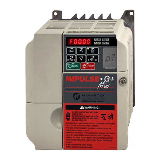
Using the Keypad All functions of the drive are accessed using the keypad. The operator can enter information using the keypad to configure the drive for their application. This information will be stored in the drive’s memory. Keypad Functions The keypad has a 5-digit LED alpha-numeric display. Indicators and keys on the keypad are described in Figure 4-1 and the following tables. -
Page 43: Keypad Led And Button Functions
Keypad LED and Button Functions Some of the keypad buttons, whose functions are described below, are dual-purpose. The dual- purpose keys have one function when used in a view-only mode, and another function when used in a programming mode. Keys and Displays on the LED Operator Display Name Function... - Page 44 LO/RE LED and RUN LED Indications Flashing Flashing Quickly During run. During During deceleration at a fast- During stop. deceleration to stop. stop. During stop by interlock When a run operation. command is input and frequency reference is 0. When run Run command is command is selected from...
-
Page 45: Quick Start Guide Information
Quick Start Guide Information Basic programming of the drive consists of entering motor parameters, choosing a motion, and selecting a speed reference. After applying power to the drive, the display will show the output frequency of 0.00. Navigation Keys: The above figure shows the keypad on the G+ Mini. These keys are used for navigation and for changing various settings within the drive. - Page 46 Use the following table to select the desired motor for your application: A01.03 - Motion Data Value Function Traverse Hoist (Default) Use the , and keys to change the value. Press to save your changes. The display will temporarily show , then A01.03.
- Page 47 Setting Motor Full Load Amps: Locate the nameplate on your motor to find the Full Load Amps (FLA), and the motor RPM. Press the key once to move the cursor to the left most spot. Use the keys to navigate to the “E” menu. The display should show E01.01. Press the key once to move the blinking digit to the right.
- Page 48 Parameters The parameters are organized by function group, that determine how the drive functions. These parameters are programmed in the drive’s software as measurable values or options—both of which will be referred to in this manual as settings. While some of these parameters are associated with one setting, others are tied to a number of possible settings.
-
Page 49: Parameter Modes
Parameter Modes All parameters are organized under four modes: Operation Mode Drive operation is enabled. Drive status LED lights. Programming Mode Parameter access levels, control method, motion, speed control mode, and passwords are selected. Parameters are set/read. Items to be set/read vary depending on the access level setting. Auto-Tuning Mode Motor parameters are automatically set by entering tuning data (motor nameplate values) when using V/f or OLV control method. - Page 50 IMPULSE•G+ Mini Structure of Parameters Group Function Monitor Fault Trace Monitor Fault History Maintenance Motor Initialization Parameters Initialize User-Defined Parameters Preset References Reference Limits Application Sequence/Reference Source Acceleration/Deceleration Jump Frequencies Quick Stop Reverse Plug Simulation Micro-Positioning Travel Limits Phantom Stop Klixon Load Check II Special...
-
Page 51: Initialization Set-Up
Initialization Set-up Parameter Access Level (A01.01) This parameter controls the level of access for all the parameters in the drive. Using this parameter controls the “masking” of parameters according to the access level selected. There are three access levels available - BASIC, ADVANCED and USER. When the access level is set to ADVANCED (A01.01 = 0002), it will allow access to all parameters outlined in this manual. - Page 52 Select Motion (A01.03) Set this parameter to match the motion of application. See tables 4.1 and 4.2 (X-Press Programming) for details. Setting Description Access Level Traverse - Decelerate to stop upon removal of RUN command. Basic/Adv Standard Hoist - Immediate stop upon removal of RUN command Basic/Adv Braketronic Speed Reference (A01.04)
- Page 53 Parameters Changed by X-Press Programming Table 4-1: Traverse (A01.03= 00) B01.01 B01.02 B01.03 B01.04 B01.05 B01.17 B01.18 B02.03 B03.03 B05.01 B05.02 A01.04 Description Speed Speed Speed Speed Speed Ref. Lower Stopping Jog Ref Ref Priority Accel Time 1 Decel Time 1 Limit Method 2-Speed Multi-Step...
- Page 54 Parameters Changed by X-Press Programming Table 4-2: Standard Hoist (A01.03 = 01) B01.01 B01.02 B01.03 B01.04 B01.05 B01.17 B01.18 B02.03 B03.03 B05.01 B05.02 A01.04 Description Speed Speed Speed Speed Speed Ref. Lower Stopping Jog Ref Ref Priority Accel Time 1 Decel Time 1 Limit Method 2-Speed Multi-Step...
- Page 55 Parameters Changed by X-Press Programming Table 4-3: Braketronic (A01.03 = 04) B01.01 B01.02 B01.03 B01.04 B01.05 B01.17 B01.18 B02.03 B03.03 B05.01 B05.02 A01.04 Description Speed Speed Speed Speed Speed Ref. Lower Stopping Jog Ref Ref Priority Accel Time 1 Decel Time 1 Limit Method 2-Speed Multi-Step...
- Page 56 To reset the oPE04 fault, set A01.05 = 5550. This will copy the parameters from the terminal board to the control board. Check and verify your kVA setting (O02.04) before operating the drive. Please contact Magnetek support for assistance. Password Entry 1 (A01.06) This parameter enables the user to set a password that inhibits the programming of parameters A01.01 ~ A01.08 and locks the remaining parameters in the drive except those stored in the User...
- Page 57 To clear a parameter stored in the A02.xx, change the value to “----”. Change the Access Level to User Program (A01.01 = 0000). Password Entry 2 (A01.08) Used to access OEM specific crane and hoist functions. IMPULSE•G+ Mini Advanced Instruction Manual – March 2014 4-19...
-
Page 58: Auto-Tuning
When the motor cannot be disconnected from the load, perform a stationary or non- rotating Auto-Tune. NOTE: Contact Magnetek Inc. Service Department if an Auto-Tune can not be performed. C A U T I O N The brake output is not energized during Auto-Tune. The brake must be manually released before Auto-Tuning and unreleased when Auto-Tuning is complete. -
Page 59: Using Auto-Tuning
Using Auto-Tuning With the keypad, use the UP or DOWN arrow keys to show the auto-tuning menu . Press the ENTER key and scroll through the tuning parameters using the UP Arrow key and enter each of the required parameter settings. Press the RUN key to begin the Auto-Tuning process when the display shows the RUN10 or RUN12 message. - Page 60 This page intentionally left blank. IMPULSE•G+ Mini Advanced Instruction Manual – March 2014 4-22...
-
Page 61: Chapter 5: Programming Features
C h a p t e r Programming Features... - Page 62 This page intentionally left blank. IMPULSE•G+ Mini Advanced Instruction Manual – March 2014...
-
Page 63: Application
A01.04. The two functions are not intended to work in conjunction. * Initial value is determined by X-Press Programming (Table 4.1-4.2). **Maximum frequency above 150 HZ is available, consult Magnetek. IMPULSE•G+ Mini Advanced Instruction Manual – March 2014... - Page 64 Table 5-1: Multi-Step Speed Processing by Multi-Function Input (B01.01 ~ B01.16) Forward/Reverse Fwd/Rev Jog-Fwd/ H01.01 = 80 Multi-Step Speed 2 Multi-Step Speed 3 Multi-Step Speed 4 Multi-Step Speed 5 Rev Inch H01.01~06 Speed Reference H01.02 = 81 H01.01 ~ .06 = 00 H01.01 ~ .06 = 01 H01.01 ~ .06 = 02 H01.01 ~ .06 = 03...
-
Page 65: Reference Limits
Reference Limits These parameters will limit the frequency range as a percentage of maximum output frequency (E01.04). An alternate upper limit frequency can be used during operation when a Multi-Function Input (MFI) is set to 59 (Alt F-Ref UpLimit) and the MFI is on. Alternate Upper Limit Frequency = (B02.04)% x (E01.04). -
Page 66: Sequence/Reference Source
If you do operate the drive locally, be aware that the crane or hoist will move when you press the RUN button. If you have questions, contact Magnetek. Stopping Method B03.03 selects the stopping method suitable for the particular application. - Page 67 Decel to Stop (B03.03 = 00) Upon removal of the FWD or REV run command, the motor decelerates at a rate determined by the time set in deceleration time 1 (B05.02) and DC injection braking is applied after the DC injection start frequency, D01.01, has been reached.
- Page 68 Coast to Stop (B03.03 = 01) Upon removal of the FWD or REV run command, the motor starts to coast and the electric brake sets. Figure 5-4: B03.03 = 01 (Coast to Stop) without DC Injection Figure 5-5: B03.03 = 01 (Coast to Stop) with DC Injection IMPULSE•G+ Mini Advanced Instruction Manual –...
- Page 69 DC Injection Braking (B03.03 = 02) Figure 5-6: B03.03 = 02 (DC Injection at Stop) without DC Injection at Start Figure 5-7: B03.03 = 02 (DC Injection at Stop) with DC Injection at Start IMPULSE•G+ Mini Advanced Instruction Manual – March 2014...
- Page 70 Decel with Timer (B03.03 = 04) Figure 5-8: B03.03 = 04 (Decel with timer) without DC Injection IMPULSE•G+ Mini Advanced Instruction Manual – March 2014 5-10...
- Page 71 Figure 5-9: B03.03 = 04 (Decel with timer) with DC Injection, where C12.02 > D01.04 Figure 5-10: B03.03 = 04 (Decel with timer) without DC Injection, where D01.04 > C12.02 IMPULSE•G+ Mini Advanced Instruction Manual – March 2014 5-11...
- Page 72 Fast Stop (H01.xx = 40 or 42) Figure 5-11: H01.XX = 40 or 42 (Fast Stop) without DC Injection Figure 5-12: H01.XX = 40 or 42 (Fast Stop) with DC Injection Motor Rotation Change This parameter allows you to change the motor direction without changing the motor leads. Parameter Initial Access...
- Page 73 LOC/REM Run Select If the run reference/speed reference are switched between serial mode and drive terminal mode, B03.07 determines action after the switch. Parameter Initial Access Code Name Function Range Value Level B03.07 LOC/REM Run Sel Determines action after switching 00–01 Run/Speed reference source.
-
Page 74: Acceleration/Deceleration
Acceleration/Deceleration Acceleration time sets the time necessary for the output frequency to accelerate from 0Hz to maximum output frequency (E01.04). Deceleration time sets the time necessary for the output frequency to decelerate from the maximum output frequency (E01.04) to 0Hz. Parameter Access Code... -
Page 75: Jump Frequencies
Run Command MFI=1A Accel / Decel Changeover B05.04 B05.01 B05.03 B05.02 Frequency Output B05.02 B05.01 Brake Output NOTE: Assume the constant B03.03 is set to “00” (Decel to Stop). Figure 5-13: Normal Accel/Decel Time and Multiple Accel/Decel Changeover Jump Frequencies This function allows the “jumping”... -
Page 76: Special Functions
Special Functions The special function parameters are special crane and hoist specific functions used to control how the system will operate. These include Quick Stop™ and Reverse Plug Simulation™. Listed below are the special function parameters covered in this section. •... -
Page 77: Quick Stop
Quick Stop The Quick Stop Function provides an automatic Alternate Deceleration at Stop Command. NOTE: The Quick Stop Deceleration time differs from the normal deceleration time and is applied only when the RUN command is removed. Parameter Access Code Name Function Range Initial Value... -
Page 78: Reverse Plug Simulation
Reverse Plug Simulation™ The Reverse Plug Simulation provides an automatic alternate deceleration time/acceleration time at a change direction command before the brake sets. The deceleration time and the acceleration time are set independently of the normal acceleration and deceleration times. Parameter Access Code... -
Page 79: Micro-Positioning Control
Micro-Positioning Control™ Micro-Positioning Control function can provide a reduced speed range operation for precise positioning. Enabled by a Multi-Function Input, it multiplies the normal speed reference by the Micro-Speed Gain. Two Micro-Speed Gains are available: Gain 1 (C02.01) and Gain 2 (C02.02). They can be adjusted and enabled independently. -
Page 80: Travel Limits
Travel Limits This function can automatically slow and stop a crane or hoist when it reaches the end of the travel limits. Two types of limit inputs (slow and stop) are available in both travel directions. Inputs can be programmed through H01.01–H01.07. When the crane reaches either the Upper Limit 1 (UL1) or Lower Limit 1 (LL1), the drive will decelerate to the Upper and Lower Limit speeds C03.01 and C03.04 respectively. -
Page 81: Phantom Stop
Phantom Stop The Phantom Stop feature is designed to stop the drive operation using the stopping method selected in C03.09 when a Phantom Fault input (H01.01–H01.07 = 5F or 63) is active. The drive will indicate a Phantom Fault has occurred by blinking the LED on the RUN key in sequence of two short bursts. The drive will resume normal operation when a Phantom Fault is removed. -
Page 82: Load Check Ii
Load Check II™ The Load Check II function is a load-limiting feature which ensures the programmed load limit of the hoist is not exceeded. It prevents the lifting (and potential stall) of a load that is overweight. When the IMPULSE•G+ Mini detects an overload condition it prevents any further lifting. The load may then be lowered at the speed that is specified by the Load Check Lowering Speed (C05.08). - Page 83 4. With Load Check disabled, lift the rated load a foot or two off the ground. 5. Set C05.01 equal to 09. 6. Press and hold the Hoist (up) command button on the pendant or radio for full speed operation (60 Hz).
- Page 84 Parameter Access Code Name Function Range Initial Value Level C05.03 LC Setting Time Sets the time to hold the output frequency 0.00–2.55 0.15 allowing the output current/torque to stabilize. C05.04 LC Testing Time Sets the time (after the LC Setting Time) 0.00–2.55 0.25 for comparing output current/torque to...
-
Page 85: Swift Lift
Swift-Lift™ Swift-Lift provides additional productivity by allowing a hoist to quickly move into position by increasing speeds under light or no load conditions. Swift-Lift will enable the motor to over-speed by calculating the maximum safe speed and automatically accelerating to this speed. However, the maximum speed cannot exceed the lesser of the Swift-Lift Forward Speed (C06.02) or Swift-Lift Reverse Speed (C06.03) and the Max Output Frequency (E01.04). - Page 86 Configuring the Swift-Lift Function: Using Multi-Step 2, 3, 5 (A01.04 = 00, 01, or 02): If the system is using Multi-Step as the Speed Control Method, use the following instructions to set up Swift-Lift. 1. Set V/f Selection (E01.03) = 0F to allow for a custom V/f pattern. NOTE: Choosing a Custom V/f pattern will require setting of E01.01 ~ E01.13 parameters to the current V/f selection.
- Page 87 running speed reference (see step 3). a. For example: if the maximum normal running speed is at 60 Hz, set C06.06 to 58 or 59 Hz as the Swift-Lift Enabling Speed. Using Uni-Polar Analog (A01.04 = 05): If the system is using Uni-Polar Analog as the Speed Control Method, use the following formula to adjust the constants H03.03 (Gain Multiplier for Terminal A1 analog input signal) or H03.11 (Gain Multiplier for Terminal A2 analog input signal): Gain Terminal A1: H03.03 = (60 Hz x 100) / E01.04...
- Page 88 Figure 5-17: Swift Lift Timing Diagram IMPULSE•G+ Mini Advanced Instruction Manual – March 2014 5-28...
-
Page 89: Torque Limit (Open Loop Vector Only)
Torque Limit (Open Loop Vector Only) IMPULSE•G+ Mini dynamically controls the torque output of the motor at all times when the control method is set to Open Loop Vector (A01.02 = 02). The Torque Limit Function limits the amount of motor torque on all four quadrants of vector control operation: •... -
Page 90: Brake Delay Timers
Brake Delay Timers This function is used in trolley or bridge applications. It can reduce the mechanical brake wear when the operator tries to position a load. This function is available only in traverse mode and the constant B03.03 must be set to 04 (Decel With Timer). -
Page 91: Maintenance Timer
Maintenance Timer The maintenance timer feature will set an output after a pre-determined period of time (hours) to alert an operator to perform or take some action, i.e. grease the bearings. To use this feature, program the number of hours between each maintenance cycle in C12.05. Then program a multi-function input for maintenance timer enable (H01.01–H01.07 = 043). -
Page 92: Inching Control
Inching Control Inching Control Function can be enabled by programming data 17, 18, and 19 respectively to the multi-function input terminals (H01.01–H01.07). The frequency reference used during inching is determined by B01.17 (Jog Reference). C A U T I O N A directional input is not needed on terminals S1 or S2. -
Page 93: Tuning
Tuning These parameters help tune the motor for your application, which include Torque Compensation and S-Curve characteristics for smoother transition during machine acceleration and deceleration. Below are the parameters included in this section. • D1 DC Injection • D2 Automatic Slip Compensation •... - Page 94 Parameter Access Code Name Function Range Initial Value Level D01.08 Magnetic Flux Compensation Sets the magnetic flux 0000–1000 0000 compensation as a percentage of the no load current value (E02.03). D01.15 Mechanical Weakening Changes the DC Injection 000–100% Detection Speed Level braking reference one second after start.
-
Page 95: Automatic Slip Compensation
Automatic Slip Compensation As the load becomes larger, the motor speed is reduced and the motor slip increases. The slip compensation function keeps the motor speed constant under varying load conditions. D02.01 sets the slip compensation gain. When the gain is “1.0”, the output frequency is increased by 1% of the E01.06 setting at rated current. - Page 96 When more torque is needed, increase the torque compensation gain in one-tenth (0.1) increments. Increase the setting when the wiring distance between the inverter and the motor is 100ft. or longer. If the motor generates excessive vibration or oscillates, decrease the torque compensation. Increasing torque compensation gain increases motor torque, but an excessive increase may cause the following: •...
-
Page 97: Dwell Function
Dwell Function The Dwell Function is used to temporarily hold the output frequency at a set reference for a set time. This function can be used when driving a motor with a heavy starting load. This pause in acceleration reduces traditionally high starting current. Enable by setting H01.01–H01.07 = 65. NOTE: This function is only available when using Braketronic (A01.03 = 06). -
Page 98: S-Curve Acceleration/Deceleration
S-Curve Acceleration/Deceleration An S-Curve pattern is used to reduce shock and provide smooth transitions during machine acceleration and deceleration. S-Curve characteristic time is the time from the output frequency to the set accel/decel time. See S-Curve Characteristic timing diagrams below and on the following page. -
Page 99: Carrier Frequency
Figure 5-23: S-Curve Characteristics–FWD/REV Operation Carrier Frequency Parameter Access Code Name Function Range Initial Value Level D10.01 CT/VT Selection Constant Torque/Variable Torque 00, 01 Selection 00 Heavy Duty 01 Normal Duty D10.02 Carrier Frequency Selection Carrier Frequency Selection 00–0F 00 2 kHz (low noise) 01 2 kHz 02 5.0 kHz 03 8.0 kHz... -
Page 100: Hunting Prevention
Hunting Prevention Occasionally, in an application, resonance between the internal control system and the mechanical system causes current instability. This is called hunting, and may cause a crane to vibrate at a lower speed (up to 30 Hz) and light load. The hunting prevention function monitors the motor flux and uses a special control circuit to “smooth out”... -
Page 101: Motor Parameters
Motor Parameters Motor data such as full load amps and V/f patterns are selected with the following parameters. These parameters include the ability to select and set up custom V/f patterns for the type of motor used. • E1 V/f Pattern •... - Page 102 Table 5-3: Overvoltage Trip Braking Transistor Inverter E1-01 Voltage Setting Trip Reset 150-255 400V 380V 380V 375V 400 800V 760V 760V 750V <400 720V 680V 660V 650V Table 5-4:V/f Parameters Parameter Initial Access Code Name Function Range Value Level E01.03 V/f Selection Selection V/f Pattern 00–0F, FF...
- Page 103 Table 5-5: Voltage/Frequency Pattern Options for 230 V Class E01.04 E01.05 E01.06 E01.07 E01.08 E01.09 E01.10 E01.11 E01.12 E01.13 E01.03 60.0 230.0 60.0 15.0 60.0 230.0 60.0 16.1 60.0 230.0 60.0 17.3 10.4 60.0 230.0 60.0 18.4 11.5 60.0 230.0 60.0 19.6 12.7...
-
Page 104: Motor Set-Up
Motor Set-up E2 constants define motor parameters. Normally, the default settings for E2 constants are determined by KVA selection (O02.04). In open loop vector control the E2 constants will be set automatically during auto-tuning. If the control method is V/f (A01.02 = 00), the motor rated current should be entered into E02.01. -
Page 105: Option Parameters
Option Parameters • F1 Pulse Generated Option Set Up Pulse Generated (PG) Control The following option parameters are used to set and control the action for the Pulse Generated (PG) input and output, including overspeed detection. These parameters become visible when the pulse generator function (H06.01) is set to 03 and the control method is set to OLV (A01.02 = 02). -
Page 106: Terminal Parameters
Terminal Parameters There are both digital and analog inputs and outputs that can be programmed for customized operation and sequencing. These include input and output terminal selection along with serial communication. Listed below are the parameters in this section that are customizable for your system. - Page 107 Reference Parameter Page Initial Access Code Name Function Number Range Value Level 09 Lower Limit 2 N.O. Lower Limit - STOP; Normally 5-20 Basic/Adv Open. LL2 - blinking 0A Upper Limit 1 N.C. Upper Limit - SLOW DOWN; 5-20 Basic/Adv Normally Closed.
- Page 108 Reference Parameter Page Initial Access Code Name Function Number Range Value Level 20 thru 2F External Fault Desired setting is possible. 5-53 Basic/Adv Input mode: N.O./N.C., Detection mode: Always/ During Run (See external fault response selection table 5-7) 30 Program Lockout Program Lockout Closed: Parameters enabled to write...
- Page 109 Reference Parameter Page Initial Access Code Name Function Number Range Value Level 59 Alternate Upper Alternate Reference Upper Basic/Adv Frequency Limit Frequency 5A Maintenance Reset Reset Maintenance Timer 5-33 (C12.05 - C12.06, U01.52) 5B BE6 Up Speed Limit Limit Fref to C08.17 (BE6 Up Speed Limit) 5F Phantom Fault N.C.
-
Page 110: External Fault Response Selection
External Fault Response Selection It is sometimes desirable to have at least one external fault input to the drive. To properly program a multi-function input (H01.01 to H01.07) for this purpose an external fault response must be selected. The table below shows the possible selections for an external fault response. Table 5-7: External Fault Selection Input Level... -
Page 111: Digital Outputs
Digital Outputs The IMPULSE•G+ Mini has three multi-function control outputs (one relay, two open collector) for indicating various conditions. The following table lists the function selections for the multi-function contact outputs and indicates the control modes during which each function can be enabled. Reference Parameter Page... - Page 112 Reference Parameter Page Initial Access Code Name Function Number Range Value Level 015 Freq Detect 3 Closed when output frequency 5-72 L04.03 016 Freq Detect 4. Closed when output frequency 5-72 L04.03 017 Trq Det 1 N.C. Open when torque > L06.02 5-75 Basic/Adv for longer than L06.03 time...
- Page 113 Reference Parameter Page Initial Access Code Name Function Number Range Value Level 03F Klixon Closed when MFDI 56 or 57 5-21 is on - motor is overheating 040 ~ FF Fault Closed on specific faults Annunciate 101 Inverse Zero Speed Open when the output Basic/Adv frequency is below B02.02 or...
- Page 114 Reference Parameter Page Initial Access Code Name Function Number Range Value Level 11B Inverse Reverse Open when running REV/ Direction DOWN 11C Inverse Swift-Lift Open when Swift Lift is active 5-26 Active 11D Inverse Baseblock Closed during baseblock 2 N.C. 120 Inverse Auto-Reset Open when auto-reset is 5-79...
-
Page 115: Analog Inputs
Analog Inputs The IMPULSE•G+ Mini has two analog inputs (two multi-function and one reference) for the external input of numerous references and limits. Parameter Initial Access Code Name Function Range Value Level H03.01 Terminal A1 Signal Select Voltage for Terminal A1 analog Basic/Adv input signal 00 0VDC to 10VDC... - Page 116 Parameter Initial Access Code Name Function Range Value Level H03.09 Terminal A2 Signal Select Selects the signal level for Terminal 00–03 Basic/Adv 00 0VDC ~ 10VDC (switch S2 must be in the “V” position) Basic/Adv 02 4 to 20mA (switch S2 must be in the “I” position) Basic/Adv 03 0 to 20mA (switch S2 must be in the “I”...
-
Page 117: Analog Outputs
Analog Outputs The IMPULSE•G+Mini has two analog outputs for the external monitoring of drive conditions. Parameter Initial Access Code Name Function Range Value Level H04.01 Terminal AM Select Assigns one of the following 101–162 functions for analog output Terminal AM. 101 Frequency Reference 102 Output Frequency 103 Output Current... -
Page 118: Serial Communication Set-Up
Serial Communication Set-up The IMPULSE•G+ Mini uses terminals R to communicate MODBUS RTU (RS-485/422) protocol. Parameter Initial Access Code Name Function Range Value Level H05.01 Serial Comm Address Serial communication address 00–20 Basic/Adv (hexadecimal) H05.02 Serial Baud Rate Sets the baud rate (bits per 00–08 Basic/Adv second) - Page 119 Parameter Initial Access Code Name Function Range Value Level H05.11 Communication Enter Function Select whether or not an Enter 00, 01 Select Command is required to save parameter data to drive 00 Enter Command must be used (G+ Series 2/3 Method) 01 Enter Command not required (P3S2 method) H05.12...
-
Page 120: Pulse Inputs
Pulse Inputs Parameter Initial Access Code Name Function Range Value Level H06.01 Pulse Input Selection Sets the function of the Pulse 00, 03 Input Terminal (RP) 00 Frequency Reference 03 Encoder Feedback H06.02 Pulse Input Scaling Sets the number of pulses equal 1,000 –... -
Page 121: Protection Parameters
Protection Parameters The IMPULSE•G+ Mini has the ability to protect both the drive’s hardware and motor by allowing various means to detect and take corrective action when a condition occurs. These include motor overload detection, torque detection, and the ability to perform a self-diagnostic check, and then resume operation after a fault is cleared. - Page 122 Parameter Initial Access Code Name Function Range Value Level L01.01 Motor Overload Fault Select Enable/disable motor overload 00–03 Basic/Adv detection. 00 Disabled Disables the motor thermal overload protection 01 Standard Fan Cooled Selects a motor with limited cooling capability below rated (base) speed when running at 100% load.
-
Page 123: Power Loss Ride Thru
Figure 5-25: Motor Protection Operation Time Power Loss Ride Thru Parameter Initial Access Code Name Function Range Value Level L02.01 Power-Loss Selection Enables/disables the Power Loss 00–02 Ride Thru function 00 Disable Disabled 01 Enable Drive will restart if power returns within L02.02 02 CPU Power Active Drive will restart if power returns... -
Page 124: Stall Prevention
Stall Prevention C A U T I O N This function automatically adjusts the output frequency, acceleration and/or deceleration rates in order to continue operation without tripping or “stalling” the inverter. Parameter Initial Access Code Name Function Range Value Level L03.01 Stall Prevention Accel Enable/disable stall... - Page 125 The stall prevention/current limit level during acceleration is set as a percentage of inverter rated current. Setting L03.01 = 00 disables current limit during acceleration. During acceleration, if the output current exceeds this current limit level (L03.02), acceleration stops and frequency is maintained.
- Page 126 Parameter Initial Access Code Name Function Range Value Level L03.03 Stall Prevention Constant Stall prevention limit 0–100% Basic/Adv HP Limit When a motor is used above rated speed (E01.06), the output characteristics change from constant torque to constant HP (See Figure 5-27). During acceleration above rated speed, the stall prevention current limit level is automatically reduced for smoother acceleration.
- Page 127 Parameter Initial Access Code Name Function Range Value Level L03.05 Stall Prevention Run Enable/Disable stall 00–02 Basic/Adv Select prevention during running 00 Disable See Table 5-9 01 Decel Time 1 See Table 5-9 02 Decel Time 2 See Table 5-9 Sets a function to prevent stalling during an overload condition while running at constant speed.
- Page 128 Parameter Initial Access Code Name Function Range Value Level L03.06 Stall Prevention Run Stall prevention level during 30–150% Basic/Adv Level run. The stall prevention/current limit level during running is set as a percentage of inverter rated current. A setting of L03.05 = 00 disables current limit during running. During speed agree, if the output current exceeds this current limit level (L03.06) during running, deceleration starts.
- Page 129 Parameter Initial Access Code Name Function Range Value Level L03.17 Overvoltage Suppression Sets the desired value for the 150–400 VDC 370 and Stall Prevention DC bus voltage during overvoltage suppression and Stall Prevention during deceleration. Enabled only when L03.04 = 02 or L03.11 = 01.
-
Page 130: Reference Detection
Reference Detection The IMPULSE•G+ Mini utilizes three different functions for detecting output frequency: • When frequency agree is enabled using the multi-function contact outputs (H02.XX = “002” or “013”), the contact closes whenever the output frequency “agrees” with the frequency reference, plus or minus the speed agree detection width. •... - Page 131 Parameter Initial Access Code Name Function Range Value Level L04.07 Speed Agree Detection Sets the detection level during 00, 01 baseblock 00 No detection during baseblock 01 Detection always enabled IMPULSE•G+ Mini Advanced Instruction Manual – March 2014 5-71...
-
Page 132: Torque Detection
Torque Detection The overtorque detection circuit activates when the motor load causes the motor current to exceed the overtorque detection level (L06.02). When an overtorque condition is detected, alarm signals will be shown on the keypad as well, and can be sent to a multi-function output. To output an overtorque detection signal, select torque detection 1 at either of the multi-function contact outputs (H02.xx = “00B,”... - Page 133 Parameter Initial Access Code Name Function Range Value Level L06.02 Torque Detection 1 Level Sets the overtorque detection as 0–300% Basic/Adv a percentage of inverter rated current, during V/f control, and motor rated torque during vector control. L06.03 Torque Detection 1 Time The overtorque detection delay 0.0–10.0 sec 0.1 Basic/Adv...
- Page 134 Parameter Initial Access Code Name Function Range Value Level L06.05 Torque Detection 2 Level Torque Detection 2 Level 0–300% L06.06 Torque Detection 2 Time Torque Detection 2 Time 0.0–10.0 sec L06.08 Mechanical Weakening Determines the action to take 00–08 Detection Selection during and after detection 00 Disabled 01 Speed (signed) >...
-
Page 135: Hardware Protection
Hardware Protection The IMPULSE•G+ Mini comes equipped with a number of built-in functions designed to protect the inverter and its components from damage. Parameter Initial Access Code Name Function Range Value Level L08.02 OH Pre-Alarm Level Sets the heatsink temperature level for 50–130°C 95... - Page 136 Parameter Initial Access Code Name Function Range Value Level L08.18 Soft CLA Sel Enables/disables the software current 00–01 limit function. Limits output frequency when current exceeds 110% of rated. 00 Disabled 01 Enabled L08.19 Overheat Pre-Alarm 0.1–0.9% Frequency Reduction Rate L08.35 Mounting Selection Mounting selection...
-
Page 137: Automatic Reset
Automatic Reset When a fault occurs during operation, the IMPULSE•G+ Mini can be programmed to automatically reset the fault and restart operation. Parameter Initial Access Code Name Function Range Value Level L09.01 Auto Reset Select Activates the fault auto-reset 00, 01 Basic/Adv function. - Page 138 Example: Enable auto-reset for UV2 and CE faults. Table 5-12: Auto Reset Table (default) Digit 4 Digit 3 Digit 2 Digit 1 Binary L09.04 Binary L09.05 Table 5-13: Auto Reset Table with UV2 and CE Fault (modified) Digit 4 Digit 3 Digit 2 Digit 1 Binary...
- Page 139 Table 5-16: Binary to Hexadecimal Conversion Table 5-14: UV2 Example L09.04 Binary Binary Number Hexadecimal Number Digit 4 0000 0000 Digit 3 0000 0001 Digit 2 0000 0010 Digit 1 0011 0011 0100 0101 Table 5-15: CE Example 0110 L09.05 Binary 0111 Digit 4...
-
Page 140: Motor Tuning
Motor Tuning • N2 Automatic Frequency Regulator Tuning (OLV Only) • N6 Online Tuning Automatic Frequency Regulator Tuning (OLV Only) The Automatic Frequency Regulator (AFR) is used to achieve stability when a load is suddenly applied or removed by calculating changes in the torque current feedback, and adjusting the output frequency accordingly. - Page 141 Table 5-17: OLV Stabilization Table Control Method OLV Stabilization Level Torq. Comp Time AFR Time (N02.02) Independent setting (A01.02) Setting (N02.05) Setting (Hex) (D03.02) Set Value Set Value of D03.02 & N02.02 2 (OLV) 00 (default) Note 1 Note 1 NOTE 1: If N02.05 is changed to an FF(hex) using the digital operator, the values that were in D03.02 &...
-
Page 142: Online Tuning
Online Tuning Parameter Initial Level Code Name Function Range Value Access N06.01 Line-to-Line Motor Line-to-Line Motor Tuning 00–01 Tuning Selection 00 Disabled 01 Enabled IMPULSE•G+ Mini Advanced Instruction Manual – March 2014 5-82... -
Page 143: Operator Parameters
Operator Parameters The keypad parameters give the ability to show a variety of information such as frequency reference, motor current, input and output terminal status, along with fault trace information. Information displayed can be customized to meet your crane and hoist application. Below is a list of parameters covered in this section. - Page 144 Parameter Initial Access Code Name Function Range Value Level 164 LC Zone 165 LC Margin 401 Cumulative Operation Time 403 Cooling Fan Operation Time 404 Cooling Fan Maintenance 405 Capacitor Maintenance 406 Soft Charge Bypass Relay Maintenance 407 IGBT Maintenance 408 Heatsink Temperature 410 kWh;...
-
Page 145: Keypad Key Selection
Selection Determines the model number of the 60–90 Basic/ drive, which is based on the kVA rating. The following in this column are Magnetek model numbers. *Initial value determined by Inverter model. 60 2A0001 Not used. 61 2A0002 2001-G+M... -
Page 146: Clear History
Parameter Initial Access Code Name Function Range Value Level 63 2A0006 2005-G+M 64 -- Not used 65 2A0010 2008-G+M 66 2A0012 2011-G+M 67 2A0018 Not used 68 2A0020 2017-G+M 69 -- Not used 6A 2A0030 2025-G+M 6B 2A0040 2033-G+M 6C -- Not used 6D 2A0056 2047-G+M... - Page 147 Parameter Initial Access Code Name Function Range Value Level O03.02 Elapsed Time Selection Selects how the Elapsed Time is 00, 01 accumulated 00 Power On Time 01 Running Time O03.03 Fan On Time 0000–9999hr 0000 O03.05 Capacitor Maintenance 000–150% Time O03.07 Inrush Preventative 000–150%...
-
Page 148: Monitor Parameters
Monitor Parameters Monitor Parameter Access Code Name Function Units Level U01.01 Frequency Reference Frequency Reference Basic/Adv U01.02 Output Frequency Inverter Output Frequency Basic/Adv U01.03 Output Current Inverter Output Current Basic/Adv U01.04 Control Method Displays the value of A01.02 Basic/Adv U01.05 Motor Speed Motor Speed (OLV only) U01.06... - Page 149 Parameter Access Code Name Function Units Level U01.12 Inverter Control Status Operation Status Basic/Adv U01.13 Elapsed Time Cumulative operation time at drive. Defined by O03.02. hours Basic/Adv U01.14 Flash ID Flash ROM software ID number Basic/Adv U01.15 Terminal A1 Level External Terminal input level Basic/Adv U01.16...
-
Page 150: Fault Trace
Fault Trace Parameter Access Code Name Function Units Level U02.01 Current Fault Displays the most recent fault detected before being reset Basic/Adv U02.02 Last Fault Displays the most recent fault after being reset (same as Basic/Adv U03.01) U02.03 Frequency Reference @ Freq ref when fault was detected Basic/Adv Fault... -
Page 151: Maintenance
Parameter Access Code Name Function Units Level U03.20 Elapsed Time 10 Elapsed time of tenth most recent fault U03.21 Accumulated Operations Displays the number of FWD and REV commands U03.22 U03.21 Rollovers Increments when U03.21 reaches 65535. U03.21 is set to zero. - Page 152 Parameter Access Code Name Function Units Level U06.03 ASR Input U06.04 ASR Output U06.05 Output Voltage Reference (Vq) U06.06 Output Voltage Reference (Vd) U06.07 ACR (q) Output U06.08 ACR (d) Output U06.20 Frequency Reference Bias (Up/Down2) U06.21 Offset Frequency U06.36 GAIA Communication Error U06.37...
-
Page 153: Chapter 6: Troubleshooting
C h a p t e r Troubleshooting IMPULSE•G+ Mini... - Page 154 This page intentionally left blank. IMPULSE•G+Mini Advanced Instruction Manual – March 2014...
-
Page 155: Troubleshooting The Drive
Troubleshooting the Drive In this troubleshooting section, “check” means investigating whether an item is functioning and in an acceptable physical condition, and then taking corrective action (adjusting, fixing, replacing, etc.) as necessary. In the Corrective Action column, you may not have to perform all of the steps to correct the problem. -
Page 156: Drive Faults, Alarms And Indicators
Symptom Corrective Action Motor rotates, but at minimum speed only. 1. Check wiring of speed inputs and verify inputs (U01.10). 2. Verify speed reference setting (A01.04). 3. Verify reference and run source settings are correct (B03.01, B03.02). 4. Verify reference priority setting (B01.18). 5. - Page 157 Fault Code Fault or Indicator Name/Description Corrective Action CPF02 A/D Conversion Error. An A/D conversion 1. Cycle power to the drive. error occurred. 2. Ensure that the control board terminals and wiring are shielded from electrical noise. 3. Check resistance of potentiometer. 4.
- Page 158 Fault Code Fault or Indicator Name/Description Corrective Action User is trying to give a run command while a 1. Check input terminals. FWD or REV is present at Power Up. 2. Check H01.01 to H01.07 programming. Drive Not Ready Both FORWARD/UP and REVERSE/DOWN 1.
- Page 159 Fault Code Fault or Indicator Name/Description Corrective Action An open phase occurred at the inverter output. 1. Check for broken wires in output cable. 2. Check for open winding in the motor. Output Phase Loss 3. Check for loose terminals. Lower Limit 1—SLOW DOWN 1.
- Page 160 Fault Code Fault or Indicator Name/Description Corrective Action OPE03 Multi-Function Input Setting Fault. Set 1. Check the settings for H01.01 to H01.07, values other than “F” and “FF” are duplicated. verify that the same input is not used twice. Terminal OPE04 Parameters do not match.
- Page 161 Fault Code Fault or Indicator Name/Description Corrective Action Upper Limit 2—STOP Indicator. Upper 1. May not require corrective action. Limit 2—STOP switch status is changed. 2. Check the position of the Limit Switch. Upper Limit 2 Err 3. Check the condition of the Limit Switch. 4.
-
Page 162: Fault Display And Corrective Actions At Auto-Tuning
Fault Display and Corrective Actions at Auto-Tuning The following are fault displays and corrective actions at auto-tuning. If any of the following faults are found, the digital operator displays that fault’s contents; the motor coasts to stop if it is under operation. -
Page 163: Power Section Check
Power Section Check WA R N I N G Do NOT touch any circuit components while AC main power is on or immediately after the main AC power is disconnected from the unit. You must wait until the red “CHARGE” lamp is extinguished. - Page 164 Braking Circuit Test Equipment - Analog Ohmmeter set to R x 1 scale or digital multimeter set to the diode check. Ohmmeter Ohmmeter Expected Reading Expected Reading Step No. Positive Lead Negative Lead (Analog Meter) (Digital Meter) Connect to B2 Connect to B1 10 Ohms 0.5 Volts...
-
Page 165: Parameter Listings
A p p e n d i x IMPULSE•G+ Mini Advanced Parameter Listing... - Page 166 This page intentionally left blank. IMPULSE•G+ Mini Advanced Instruction Manual – March 2014...
- Page 167 IMPULSE•G+ Mini Parameter Listing Reference Parameter Parameter Name Default Range Units Page A01.01 Access Level 0001 0000~0001 4-13 0000: User 0001: Basic 0002: Advanced A01.02 Control Method 00, 02 4-13 00: V/f 02: OLV A01.03 Motion 00, 01, 04 4-14 00: Traverse 01: Hoist 04: Braketronics...
- Page 168 Reference Parameter Parameter Name Default Range Units Page B01.18 Reference Priority 00–02 00: Digital Reference Only 01: Analog Reference Only 02: Higher Reference Select B02.01 Frequency Reference Upper Limit 100.0 0.0–110.0 B02.02 Frequency Reference Lower Limit 0.0–110.0 B02.03 Reference 1 Lower Limit 2.0* 0.0–110.0 B02.04...
- Page 169 Reference Parameter Parameter Name Default Range Units Page B05.09 Accel/Decel Units 00–01 5-14 00: Unit of 0.01 Seconds 01: Unit of 0.1 Seconds B05.10 Accel/Decel Switch Frequency 120.0 0.0–150.0 5-14 B05.11 Switch Frequency Compare 00–01 5-14 00: Lower Switch Frequency 01: Upper Switch Frequency B05.12 Accel Time 3...
- Page 170 Reference Parameter Parameter Name Default Range Units Page C03.11 Klixon Action 00–01 5-21 00: Decel to Stop 01: Lower Only C05.01 Load Check 00, 01, 03, 09 -- 5-23 00: Disable 01: Enable Load Check 03: Enable Load Check Continuous 09: Load Check Set Up C05.02 LC Alarm Action...
- Page 171 Reference Parameter Parameter Name Default Range Units Page C06.04 Swift-Lift Forward Torque 0–100 5-25 C06.05 Swift-Lift Reverse Torque 0–100 5-25 C06.06 Swift-Lift Enabling Speed 59.00 0.00–150.00 5-25 C06.07 Swift-Lift Delay Time 0.0–25.5 5-25 C06.08 Swift-Lift Acceleration Gain 0.1–9.9 5-25 C07.01 Forward Torque Limit 000–300 5-29...
- Page 172 Reference Parameter Parameter Name Default Range Units Page D02.06 Magnetic Flux Characteristic 00–01 5-35 00: Slip Include 01: Slip Exclude D03.01 Torque Compensation Gain 1.00 0.00–2.50 5-36 D03.02 Torque Compensation Time 200**** 0–60000 5-36 D03.03 Forward Torque Compensation @ Start 0.0–200.0 5-36 D03.04...
- Page 173 Reference Parameter Parameter Name Default Range Units Page E01.05 Max Voltage 0.0–255.0 5-42 0.0–510.0 E01.06 Base Frequency 0.00–150.00 5-42 E01.07 Mid Frequency A 0.00–150.00 5-42 E01.08 Mid Voltage A 0.0–255.0 5-42 0.0–510.0 E01.09 Min Frequency 0.00~150.00 5-42 E01.10 Min Voltage 0.0–255.0 5-42 0.0–510.0...
- Page 174 Reference Parameter Parameter Name Default Range Units Page F01.09 Overspeed Detection Time 0.0–2.0 5-45 F01.10 Excessive Speed Detection Level 00–50 5-45 F01.11 Excessive Speed Detection Time 0.0–10.0 5-45 F01.14 PGO Detection Time 0.0–10.0 5-45 * Parameters defaults changed by X-Press Programming ** Parameters changed by E01.03 *** Value depends on drive model **** Default value depends on control method...
- Page 175 Reference Parameter Parameter Name Default Range Units Page H01.01 Input Terminal 1 Select 00–81 5-46 (See reference page for further details) 00: Multi-Step Reference 2 01: Multi-Step Reference 3 02: Multi-Step Reference 4 03: Multi-Step Reference 5 04: Speed Hold 2 05: Accel Command 06: Upper Limit 1 N.O.
- Page 176 Reference Parameter Parameter Name Default Range Units Page H01.03 Terminal 3 Select 00–81 5-46 (See reference page for further details) H01.04 Terminal 4 Select 00–81 5-46 (See reference page for further details) H01.05 Terminal 5 Select 00–81 5-46 (See reference page for further details) H01.06 Terminal 6 Select 00–81...
- Page 177 Reference Parameter Parameter Name Default Range Units Page H02.01 Output Contact (MC-MB-MA) Select 000* 000–1FF 5-51 000: Brake Release 001: Zero Speed 002: Fref. Fout Agree 1 003: Fref/Set Agree 1 004: Frequency Detect 1 005: Frequency Detect 2 006: Inverter Ready 007: DC Bus Undervolt 008: Base Block N.O.
- Page 178 Reference Parameter Parameter Name Default Range Units Page 114: (Inverse) Freq Set 2 115: (Inverse) Frequency Detect 3 117: (Inverse) Torque Detect 1 N.C. 118: (Inverse) Torque Detect 2 N.O. 119: (Inverse) Torque Detect 2 N.C. 11A: (Inverse) Forward Direction 11B: (Inverse) Reverse Direction 11C: (Inverse) Swift-Lift Active 11D: (Inverse) Base Block N.C.
- Page 179 Reference Parameter Parameter Name Default Range Units Page H03.10 Terminal A2 Select 00–1F 5-56 00: Frequency Bias 01: Frequency Gain 02: Aux Speed Reference 1 03: Aux Speed Reference 2 04: Output Voltage Bias 07: OT/UT Detection Level 0F: Not Used 10: Forward Torque Limit 11: Reverse Torque Limit 12: Regen Torque Limit...
- Page 180 Reference Parameter Parameter Name Default Range Units Page H05.07 RTS Control Select 00–01 5-58 00: Disable 01: Enable H05.09 Communication - Error Detection Time 0.0–10.0 5-58 H05.10 Output Voltage Reference 00–01 5-58 00: 0.1V 01: 1V H05.11 Communcation Enter Function Select 00–01 5-59 00: Enter Command must be used...
- Page 181 Reference Parameter Parameter Name Default Range Units Page L02.01 Power-loss Selection 00–02 5-63 00: Disable 01: Enabled 02: CPU Power Active L02.02 Power-loss Ride Thru Time 0.1 (Varies) 0.0–25.5 5-63 L02.03 Power-loss Base Block Time 01. (Varies) 0.1–5.0 5-63 L02.04 Power-loss V/f Ramp Time 0.3 (Varies) 0.0–5.0...
- Page 182 Reference Parameter Parameter Name Default Range Units Page L06.01 Torque Detection 1 Level Select 00–08 5-72 00: Disabled 01: Overtorque @ Speed Agree (Alarm) 02: Overtorque @ Run (Alarm) 03: Overtorque @ Speed Agree (Fault) 04: Overtorque @ Run (Fault) 05: Undertorque @ Speed Agree (Alarm) 06: Undertorque @ Run (Alarm) 07: Undertorque @ Speed Agree (Fault)
- Page 183 Reference Parameter Parameter Name Default Range Units Page L08.06 Input Phase Loss Detection Level 0.0–5.0 5-75 (Increasing L08.06 from default value may cause DC BUS capacitor failure) L08.07 Output Phase Loss Selection 00, 01 5-75 00: Disabled 01: Enabled L08.08 Output Phase Loss Detection Level 0.0–20.0 5-75...
- Page 184 Reference Parameter Parameter Name Default Range Units Page O01.01 User Montior Selection 104–638 5-83 104: Control Method 105: Motor Speed - OLV ONLY 106: Output Voltage 107: DC Bus Voltage 108: Output Power 109: Torque Reference - OLV ONLY 110: Input Terminal Status 111: Output Terminal Status 112: Operation Status 113: Elapsed Time...
- Page 185 5-85 00: No Change 01: Set Defaults 02: Clear All O02.04 kVA Selection 60–90 5-85 60: Not Used 61: 2001-G+M 62: 2003-G+M 63: 2005-G+M 64: Not Used 65: 2008-G+M 66: 2011-G+M 67: Not Used 68: 2017-G+M 69: Not Used 6A: 2025-G+M...
- Page 186 Reference Parameter Parameter Name Default Range Units Page O02.05 Operator M.O.P 00, 01 5-86 00: Disabled 01: Enabled O02.07 Motor Direction at power-up 00, 01 5-86 00: Forward 01: Reverse O03.01 Elapsed Time Setting 0000 0000–9999 5-86 O03.02 Elapsed Time Selection 00, 01 5-87 00: Power On Time...
- Page 187 Reference Parameter Parameter Name Default Range Units Page U01.11 Output Terminal Status 5-88 U01.12 Inverter Control Status 5-89 U01.13 Elapsed Time hours 5-89 U01.14 Flash ID 5-89 U01.15 Terminal A1 Level 5-89 U01.16 Terminal A2 Level 5-89 U01.20 Output Frequency after Soft Start 5-89 U01.28 Software CPU...
- Page 188 Reference Parameter Parameter Name Default Range Units Page U03.09 Fault Message 9 5-90 U03.10 Fault Message 10 5-90 U03.11 Elapsed Time 1 hours 5-90 U03.12 Elapsed Time 2 hours 5-90 U03.13 Elapsed Time 3 hours 5-90 U03.14 Elapsed Time 4 hours 5-90 U03.15...
- Page 189 Reference Parameter Parameter Name Default Range Units Page U06.05 Output Voltage Reference (Vq) 5-92 U06.06 Output Voltage Reference (Vd) 5-92 U06.07 ACR (q) Output 5-92 U06.08 ACR (d) Output 5-92 U06.20 Frequency Reference Bias (Up/Down2) 5-92 U06.21 Offset Frequency 5-92 U06.36 GAIA Communication Error 5-92...
- Page 190 This page intentionally left blank. IMPULSE•G+ Mini Advanced Instruction Manual – March 2014 A-26...
Need help?
Do you have a question about the 2001-G+M and is the answer not in the manual?
Questions and answers