
Related Manuals for Magnetek IMPULSE G Plus Series 4


Summary of Contents for Magnetek IMPULSE G Plus Series 4
- Page 1 PROFINET Installation Manual August 2014 Part Number: 144-27019 © Copyright 2014 Magnetek...
-
Page 2: Table Of Contents
Magnetek-Specific Control and Status Words ........ - Page 3 Drive Status Tab ............47 Network Tab .
-
Page 4: Preface And Safety
Any warnings provided by Magnetek must be promptly provided to the end user. Magnetek offers an express warranty only as to the quality of its products in conforming to standards and specifications published in the Magnetek manual. NO OTHER WARRANTY, EXPRESS OR IMPLIED, IS OFFERED. -
Page 5: Terms
Terms ® Drive: IMPULSE •G+/VG+ Series 4 ® Option: IMPULSE •G+/VG+ Series 4 SI-EP3 PROFINET option Registered Trademarks • All trademarks are the property of their respective owners. Supplemental Safety Instructions Read and understand this manual before installing, operating, or servicing this option. The option must be installed according to this manual and local codes. -
Page 6: General Safety
Do not modify the drive or option circuitry. Failure to comply could result in damage to the drive or option and will void the warranty. Magnetek is not responsible for any modification of the product made by the user. This product must not be modified. -
Page 7: Product Overview
2. Product Overview About This Product The PROFINET SI-EP3 option connects the Series 4 drive to a PROFINET network and facilitates the exchange of data. This manual explains the handling, installation, and specifications of this product. The PROFINET SI-EP3 option is a simple networking solution that reduces the cost and time to wire and install factory automation devices, while providing interchangeability of like components from multiple vendors. -
Page 8: Receiving
3. Receiving Please perform the following tasks upon receiving the option: • Inspect the option for damage. Contact the shipper immediately if the option appears damaged upon receipt. • Verify receipt of the correct model by checking the model number printed on the option nameplate. -
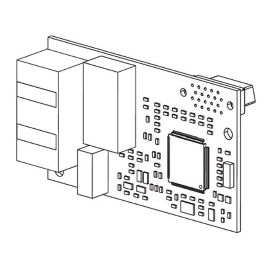
Page 9: Option Components
4. Option Components SI-EP3 PROFINET Option <1> The ground wire provided in the option shipping package must be connected during installation. <2> Refer to Option LED Display on page 10 for details on the LEDs. Figure 1: Option (Top View) Terminal CN1 The communication connector on the option is a modular RJ45 female connector designated CN1. -
Page 10: Option Led Display
Option LED Display The option has six LEDs: Bi-color Status LEDs: • Module status (MS) red/green • Network status (NS) red/green PROFINET LEDs (2 each): • Network speed-10/100 yellow • Link status and network activity-Link/Act green The operational states of the option LEDs after the power-up diagnostic LED sequence is completed are described in Table 2: Option LED States. -
Page 11: Power-Up Diagnostics
Power-Up Diagnostics An LED test is performed each time the drive is powered up. The initial boot sequence may take several seconds. After the LEDs have completed the diagnostic LED sequence, as shown in Table 3: Power-Up Diagnostic LED Sequence, the option is successfully initialized. The LEDs then assume operational conditions as shown in Table 2: Option LED States. -
Page 12: Installation Procedure
5. Installation Procedure Section Safety D A N G E R Electric Shock Hazard Do not connect or disconnect wiring while the power is on. Failure to comply will result in death or serious injury. Disconnect all power to the drive, wait at least five minutes after all indicators are off, measure the DC bus voltage to confirm safe level, and check for unsafe voltages before servicing. - Page 13 N O T I C E Damage to Equipment Observe proper electrostatic discharge (ESD) procedures when handling the option, drive, and circuit boards. Failure to comply may result in ESD damage to circuitry. Never shut the power off while the drive is running or outputting voltage. Failure to comply may cause the application to operate incorrectly or damage the drive.
-
Page 14: Prior To Installing The Option
Prior to Installing the Option Prior to installing the option, wire the drive, make necessary connections to the drive terminals, and verify that the drive functions normally without the option installed. Refer to the Instruction Manual packaged with the drive for information on wiring and connecting the drive. Figure 2 shows an exploded view of the drive with the option and related components for reference. -
Page 15: Installing The Option
Installing the Option Remove the front covers of the drive before installing the option. Refer to the Instruction Manual for directions on removing the front covers. Cover removal varies depending on drive size. This option can be inserted only into the CN5-A connector located on the drive control board. 1. - Page 16 2. With the front covers and digital operator removed, apply the LED label (H) in the appropriate position on the drive top front cover (F). Figure 4: Apply the LED Label 3. Insert the option (E) into the CN5-A connector (C) located on the drive and fasten it using one of the included screws (K).
- Page 17 4. Connect the ground wire (L) to the ground terminal (N) using one of the remaining provided screws (K). Connect the other end of the ground wire (L) to the remaining ground terminal and installation hole on the option (E) using the last remaining provided screw (K) and tighten both screws to 0.5 ~ 0.6 nm (4.4 ~ 5.3 in lb.).
- Page 18 Wiring the Option 5. Route the option wiring. Depending on the drive model, some drives may require routing the wiring through the side of the front cover to the outside to provide adequate space for the wiring. In these cases, using diagonal cutting pliers, cut out the perforated openings on the left side of the drive front cover.
- Page 19 Communication Cable Wiring The dual RJ45 network ports on the option board act as a switch to allow for flexibility in cabling topology. For example, a traditional star network topology may be employed by using a single port on the option board. Alternatively, a daisy-chained approach may be employed by using both RJ45 ports.
-
Page 20: Gsd/Gsdml Files
9. Set drive parameters in Table 5: Parameter Settings for proper option performance. GSD/GSDML Files To facilitate network implementation, obtain a GSDML file from the following website: http://www.magnetek.com/Series4Accessories IMPULSE®•G+/VG+ Series 4 Profinet Installation Manual - August 2014... -
Page 21: Option Related Drive Parameters
6. Option Related Drive Parameters The following parameters are used to set up the drive for operation with the Profinet card. Parameter setting instructions can be found in the drive’s Instruction Manual. Confirm proper setting of the all parameters in Table 5: Parameter Settings before starting network communications. - Page 22 Parameter Code Display Function Range Initial Value B03-02 Run Source 1 Source from where the RUN 0–3 1 (Set to 3 for <1> command is generated. PROFINET) Operator Digital Operator Terminals Terminals • S4-IF Interface Card • S4-I AC Digital Input Option •...
- Page 23 Table 6: F7 Parameter Settings Parameter Code Display Description Default F07-01 to IP Address Sets static IP address of the SI-EP3 option when 192 168 1 20 F07-04 parameter F07-13=0. NOTE: Parameter F07-01 sets the most significant octet. F07-05 to Subnet Mask Sets static Subnet Mask of network connection.
- Page 24 Table 7: Option Monitors Parameter Code Display Description Value Range U06-80 to Online IP Address SI-EP3 IP Address, U06-80 is the most significant 0–255 U06-83 octet. U06-84 to Online Subnet Subnet, U06-84 is the most significant octet. 0–255 U06-87 U06-88 to Online Gateway Gateway, U06-88 is the most significant octet.
-
Page 25: Profinet Messaging
This section describes the communication profile used between the PROFINET I/O network and the option. The option supports the PROFIdrive profile. Users can select between the control and status words according to the PROFIdrive profile or use the Magnetek-specific control and status words. PROFIdrive Communication Profile The Control Word and the Status Word... - Page 26 Name Value Proceed to STATE/Description Normal operation. Proceed to OPERATING. NOTE: This bit is effective only if the fieldbus RAMP_IN_ZERO interface is set as the source for this signal by drive parameters. Force Ramp Function Generator input to zero. Fault reset if an active fault exists. Proceed to 0 ->...
- Page 27 Figure 11: PROFIdrive State Machine IMPULSE®•G+/VG+ Series 4 Profinet Installation Manual - August 2014...
-
Page 28: Magnetek-Specific Control And Status Words
Magnetek-Specific Control and Status Words The Control Word and the Status Word The contents of the Control Word and the Status Word are detailed in Table 10: Magnetek-Specific Control Word and Status Word. Frequency Reference Frequency Reference is a 16-bit word containing the desired output frequency. -
Page 29: Communication
PROFINET IO in SI-EP3 The decision to use either the PROFIdrive control and status words or the Magnetek-specific control and status words is done in a hardware configuration tool (customer-supplied). The default value is the Magnetek-specific format. - Page 30 • Diagnostic and alarm mechanism • Fault buffer mechanism Magnetek SI-EP3 PROFINET I/O Modules Std Tgm 1 Table 11: Std Tgm 1 Consume Bytes Description Control Word MSB Control Word LSB Frequency Reference MSB Frequency Reference LSB Table 12: Std Tgm 1 Produce...
- Page 31 Table 14: Std Tgm 1 + 5 PZD Produce Bytes Description Status Word MSB Status Word LSB Output Frequency MSB Output Frequency LSB Configurable Input 1 MSB Configurable Input 1 LSB Configurable Input 2 MSB Configurable Input 2 LSB Configurable Input 3 MSB Configurable Input 3 LSB Configurable Input 4 MSB Configurable Input 4 LSB...
- Page 32 Bytes Description Reserved Reserved Reserved Reserved Configurable Output 1 MSB Configurable Output 1 LSB Configurable Output 2 MSB Configurable Output 2 LSB Configurable Output 3 MSB Configurable Output 3 LSB Configurable Output 4 MSB Configurable Output 4 LSB Configurable Output 5 MSB Configurable Output 5 LSB Table 16: Forty Byte IO Produce Bytes...
- Page 33 ACT: Actual Value PZD: Configurable inputs and outputs Magnetek Acyclic Parameter Access Mechanism All drive parameters can be read and written under address 0x8000 by performing a read or write with the index value of the corresponding parameter address in the drive. Refer to the Series 4 Instruction Manual for a list of these parameter addresses.
- Page 34 PROFIdrive Acyclic Parameter Access Mechanism A PROFIdrive acyclic parameter access mechanism can be used to access PROFIdrive parameters and drive parameters using an index of 0xB02E and the structure in Figure 12 for write and read requests. Requests and responses between the IO device and the IO controller or the IO supervisor are transferred with the Record Data Objects.
- Page 35 Table 18: ErrorCode1 with PNIORW Decoding Error class Meaning Error Code 0...9 (Reserved) 0 = Read error 1 = Write error 2 = Module failure 10 (0x0A) Application 3...7 = Reserved 8 = Version conflict 9 = Feature not supported 10...15 = User-specific 0 = Invalid index 1 = Write length error...
- Page 36 Field(s) Description Range Type Device Access Point (0x0000) Application Process Identifier UI32 PROFIdrive (0x3A00) Slot of the Module Access Point Slot 0x01 UI16 (MAP/PAP) Sub-slot of the Module Access Sub-slot 0x01 UI16 Point (MAP/PAP) Padding 2 bytes Index Index of the Record Data Object 0x0001 - 0x7FFF UI16 0xB02E...
- Page 37 Field(s) Description Range Byte/Word Values <1> The values of the request. In case of odd Varies based on value See Format number of bytes, a zero byte is appended to Field ensure the word structure of the telegram. <1> Only when Request ID is 0x02 (Change Parameter). The Format, Number of Values, and Value Fields are repeated for other parameters.
- Page 38 Error Meaning Used at 0x05 Incorrect data type Change access with value that does not match the data type of the parameter 0x06 Setting not permitted (can only be Change access with value unequal to 0 when this is reset) not permitted 0x07 Description element cannot be...
- Page 39 The following example shows how parameter data is transferred using the acyclic parameter access mechanism's READ and WRITE. Example 1: Reading a drive parameter To read a Magnetek Drive parameter, use the PNU of 1 and the actual address of the parameter in the SubIndex. Write Request (Read Parameter Value)
- Page 40 Negative Response to PROFIdrive Read Request PROFIdrive Profile-Specific Parameters PROFIdrive parameters contain data of the drive in standard form. Table 24 describes the supported PROFIdrive parameters. Table 24: Profile-Specific Parameters Parameter Data Type Description Unsigned16 Telegram selection Unsigned16 Fault message counter Fault number.
-
Page 41: Option High Priority Alarm Codes
Fault Buffer Mechanism The PROFIdrive profile has a mechanism that can store five fault situations to PROFIdrive parameters. Fault and diagnostic data, like fault number and fault code, can be accessed simultaneously with only one subindex. The mechanism consists of two PROFIdrive parameters: •... - Page 42 Drive Alarm Description Corrective Action Code (hex) <1> 1018 Overspeed Det (oS) • Check reference and reference gain • Check F01-24 and F01-25 settings 1019 Speed Deviation (dEV) • Check load, accel/decel times, and system mechanics • Check F01-27 and F01-28 settings 101A PG Open (PGO15) Check PG card connections...
-
Page 43: Option Low Priority Alarm Codes
Option Low Priority Alarm Codes These codes are transmitted as Manufacturer Specific Diagnostic low priority alarms that can be seen in the PLC configuration software. These low priority codes are the same codes that appear in the drive manual, except with an offset of 0x0400. Table 26: PROFINET Option Low Priority Alarm Codes Drive Alarm Drive Alarm... -
Page 44: Identification And Maintenance Functions (I&M)
Identification and Maintenance Functions (I&M) The purpose of the I&M functions is to provide support for the customer during commissioning, parametrization, and repair of the module. SI-EP3 supports I&M function 0, which can be accessed using the Record data object's read request. Function Record Data Index I&M0... -
Page 45: Alarm Mechanism
Alarm Mechanism When a fault or alarm situation occurs in the drive, the SI-EP3 adapter will send an alarm notification, which the master station must acknowledge. Refer to Table 28 for details. Table 28: Alarm Notification Attribute Description BlockHeader AlarmType PROFINET specific alarm type 0x3A00 (PROFIdrive profile) SlotNumber... -
Page 46: Web Interface
9. Web Interface The web server interface to the drive option through port 80 allows management of diagnostic information through a standard web browser. The web page is a Java applet that creates a tabbed web page. The available tabs include: •... -
Page 47: Drive Status Tab
Drive Status Tab The Drive Status tab shows basic I/O information and drive state information. Figure 14: Drive Status Tab View IMPULSE®•G+/VG+ Series 4 Profinet Installation Manual - August 2014... -
Page 48: Network Tab
Network Tab The Network tab shows the status of the option network traffic and the status of open I/O connections. Figure 15: Network Tab View Table 29: Network Monitor Descriptions Network Monitor Explanation Msg Tx OK Cumulative number of messages transmit successfully from SI-EP3. Msg Rx OK Cumulative number of messages received successfully to SI-EP3. -
Page 49: Doc Links Tab
Doc Links Tab The Doc links tab contains links to the option documentation on the Yaskawa website. Figure 16: Doc Links Tab View IMPULSE®•G+/VG+ Series 4 Profinet Installation Manual - August 2014... -
Page 50: Email Alerts Tab
Email Alerts Tab The Email Alerts tab allows the user to configure four Email Fault/Alarm conditions. When the condition is true, one email will be sent to the provided email address. Another email will not be sent until the condition becomes false and then true again. A 30-second timer prevents emails from being sent when conditions reoccur immediately after being removed. - Page 51 Parameter Access Tab The Parameter Access tab allows the user to read and write parameters from the drive. Write access is restricted until a valid password is entered. Figure 18: Parameter Access Tab View The MEMOBUS/Modbus address for the drive parameter being accessed must be entered in hexadecimal.
- Page 52 Configuration Tab The Configuration tab sets web page behavior parameters. Access is restricted unless a valid password is entered. Figure 19: Configuration Tab View Security Login Enter a valid password and click “Log in”. The button text will change to “Log out” and the status will change to “Logged in”.
- Page 53 Email Settings The “Email Server IP” text box must contain the IP address of the email server. The subnet address is configured in drive parameters F07-05 through F07-08. The configured email alerts will use the server at this address when sending emails. Enter the email server port in the “Email Port”...
- Page 54 Custom Tab The Custom tab displays a selection of quick setting parameters. Figure 20: Custom Tab View IMPULSE®•G+/VG+ Series 4 Profinet Installation Manual - August 2014...
-
Page 55: Troubleshooting
10. Troubleshooting Drive-Side Error Codes Drive-side error codes appear on the drive digital operator. Causes of the errors and corrective actions are listed in Table 30. For additional error codes that may appear on the drive digital operator, refer to the drive’s Instruction Manual. Faults Both bUS (SI-EP3 option communication error) and EF0 (External fault input from the SI-EP3 option) can appear as an alarm or as a fault. - Page 56 LED Operator Display Fault Name External Fault Input from the option. The alarm function for an external device has been triggered. Cause Possible Solution An external fault is being sent from the Remove the cause of the external fault upper controller (PLC) Reset the external fault input from the PLC device Check the program used by the PLC and make the Problem with the PLC program...
- Page 57 LED Operator Display Fault Name Option Fault (Port A) Communication ID Error. oFA30 to oFA43 Cause Possible Solution Option hardware fault Replace the option. LED Operator Display Fault Name Option fault (CN5-B) Non-compatible option is connected. oFb00 Cause Possible Solution Non-compatible option connected to the Connect the correct option to CN5-A.
- Page 58 Minor Faults and Alarms LED Operator Display Minor Fault Name Serial Communication Transmission Error Communication has not yet been established. CALL Minor Cause Possible Solution Fault (H02- XX = 10) Check for wiring errors: Communication wiring is faulty, there is Correct the wiring a short circuit, or improper connection Remove any ground shorts and reconnect loose...
- Page 59 Option Fault Monitors U06-98 and U06-99 The option can declare error/warning conditions via drive monitor parameters on the drive digital operator as shown in Table 31. Table 31: Option Fault Monitor Descriptions Status Value Fault Condition Fault Declared Description (U06-98/U06-99) No Fault No faults.
-
Page 60: Specifications
11. Specifications Table 33: Option Specifications Items Specifications Model SI-EP3 Option Conformance Passed PROFINET Conformance Class A Connector Type Dual RJ45 8-pin Shielded Twisted Pair CAT5e cable Isolated Physical Layer Physical Layer Type TCP Protocol Transformer Isolated IP Address Setting Programmable from drive keypad or network Communication Programmable from drive keypad or network:...
Need help?
Do you have a question about the IMPULSE G Plus Series 4 and is the answer not in the manual?
Questions and answers