
Related Manuals for Dionex TCC-100


Summary of Contents for Dionex TCC-100
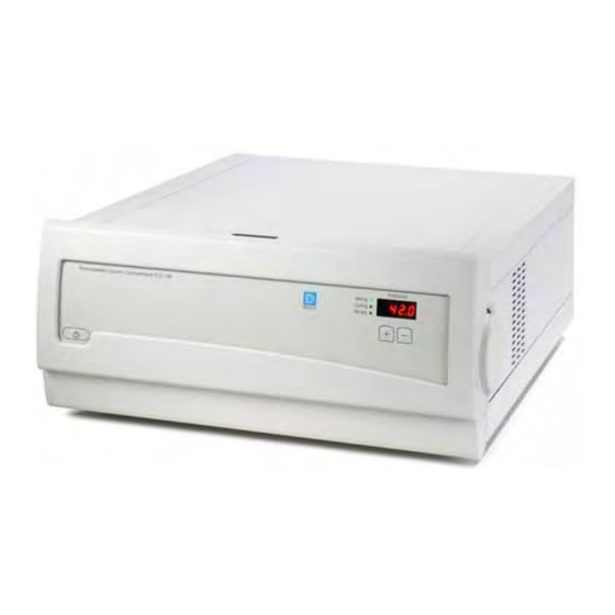
- Page 1 TCC-100 Thermostatted Column Compartment Quick Installation Guide August 2003 Rev. 2 Page 1 © 2003 Dionex...
-
Page 2: General Information
This Quick Installation Guide provides information about how to install the TCC-100 Thermostatted Column Compartment and its options. For additional information, please refer to the Operating Instructions for the instrument. 1. General Information 1.1 Preparation Bring the unit to a moderate temperature for four hours to allow any condensation that might have occurred during transit to evaporate. - Page 3 To interrupt operation without turning off the instrument, press the Standby key. This sets the instrument to standby mode. To resume operation, press the Standby key again. August 2003 Rev. 2 Page 3 © 2003 Dionex...
-
Page 4: Automated Control By Chromeleon
Follow the on-screen instructions as they appear to install the driver. If a version is found for which no driver is available, the setup aborts. For Chromeleon versions higher than 6.40, the USB installation of the TCC-100 is handled automatically during the Chromeleon setup. The user will not be required to take any other action. - Page 5 For information about the TCP/IP setup, please refer to the Operating Instructions for the TCC-100. Afterward, install the TCC-100 in the Chromeleon Server Configuration program. Follow the instructions in the corresponding sections of the Operating Instructions for the instrument or refer to the Chromeleon online Help.
-
Page 6: Installing A Column
3. Installing a Column Press Push To open the TCC-100 push the front panel The TCC-100 front panel tilts downward and against the enclosure and press the release the fan stops automatically if temperature button on top of the housing. -
Page 7: Using The Column Identification System
Expanding rivet ... onto the column as shown above. (To do so, Take the chip card. Make sure that the Dionex you can open the expanding rivet by removing logo is facing you. the rivet head from the body.) Insert the chip card (with the Dionex logo You may now close the front panel door. -
Page 8: Configuring The Column Switching Valve
From column outlet A Position 4: To detector Remove the plastic cap that protects the For a typical example for the connections on column switching valve during shipment. the valve, see the photo above. August 2003 Rev. 2 Page 8 © 2003 Dionex... - Page 9 Connect the capillary to the detector inlet to the inlet of either the second column or second valve position 4. preconditioner (here: to the eluent preconditioner installed in the top position). August 2003 Rev. 2 Page 9 © 2003 Dionex...
- Page 10 (here: to the column installed in the top position.) Please note: If valve position 2 was used for the column inlet, valve position 3 must be used for the column outlet. August 2003 Rev. 2 Page 10 © 2003 Dionex...
- Page 11 Configuration of the column switching valve and the installation of both columns is now complete. Please note: In the above picture, the Column Identification System is used for both columns. August 2003 Rev. 2 Page 11 © 2003 Dionex...
Need help?
Do you have a question about the TCC-100 and is the answer not in the manual?
Questions and answers