
Related Manuals for Dionex RF-2000


Summary of Contents for Dionex RF-2000
- Page 1 Fluorescence Detector RF-2000 Operating Instructions Version: 1.40 Datum: July 7, 2000 © 2000 Dionex Softron GmbH Doc.: RF2000_OI_E_V140.doc...
- Page 2 # EN 50082-1 (1992): Electromagnetic compatibility - Generic immunity standard Part 1: Residential, commercial and light industry Attention Dionex Softron will not accept any liability for damage, direct or indirect, caused by connecting this instrument to devices which do not meet relevant safety standards.
-
Page 3: Table Of Contents
Operating Instructions RF-2000 CONTENTS Precautions ....................3 Warnings in these Operating Instructions ..............3 Warning Labels on the Unit ..................3 Replacement of Fuses..................... 5 Precautions on Installation Site and Handling of the Unit......... 6 Precaution in the region where 240V is used as working voltage......7 Precautions on Static Electricity................ - Page 4 Operating Instructions RF-2000 Maintenance ..................... 64 Maintenance of Flow Cell ..................64 Checking the Xenon Lamp ..................70 Replacing the Fuse....................72 Changing the Set Power Supply Voltage ............... 73 Periodical Cleaning....................74 Troubleshooting ..................75 Summary of the Most Frequently Problems ............75 List of Error Messages...................
-
Page 5: Precautions
• Follow the procedures described in the operating instructions. • Observe the warnings and cautions. • Do not disassemble or modify the unit without approval from Dionex. Failing to do so may lead to a dangerous situation or damage to the instrument. - Page 6 Operating Instructions RF-2000 Important: Be sure to read this instruction manual before supplying power to this unit. • Be sure to mount the xenon lamp correctly before supplying the power to this unit (refer to 4.7 Installing the Xenon Lamp). Failing to do so may damage the main unit because high voltage around 30kV is applied to electrode when turning ON the xenon lamp.
-
Page 7: Replacement Of Fuses
Operating Instructions RF-2000 1.3 Replacement of Fuses This unit uses the following fuse. Be sure to replace the fuse of the same type and capacity. Power supply voltage: 220-240 V Part no. 706.072.0165221 250V 3.15AT Important: When the xenon lamp is lit, the flow cell is irradiated by the excitation light beam. -
Page 8: Precautions On Installation Site And Handling Of The Unit
1.4.7 Repair and maintenance of the unit Normal maintenance of this unit can be performed without removing the cover. Do not remove the cover at the normal maintenance. Contact the Dionex Service if repair requires to remove the cover of the main body. -
Page 9: Precaution In The Region Where 240V Is Used As Working Voltage
Operating Instructions RF-2000 1.5 Precaution in the region where 240V is used as working voltage 1.5.1 Confirming the working voltage The voltage setting must correspond to the working voltage used. When the working voltage is between 220V and 230V, it is not necessary to change the factory setting (230Vac). -
Page 10: Precautions On Static Electricity
Operating Instructions RF-2000 1.6 Precautions on Static Electricity Liquid chromatography using flammable organic solvents as mobile phase requires proper care against fire, explosion, etc. Particularly, among various possible accidents, those caused by static electricity are difficult to anticipate, and tend to occur only with unexpected conditions which often make countermeasures insufficient. - Page 11 Operating Instructions RF-2000 Fig.: Conditions which may cause accidents 1.6.2 Preventive Measures against Accidents The principal preventive measure is the prevention of charging and storage of static electricity among those items shown in Mechanism of Static Electrical Discharge Accidents. The preventive measures are shown below. It is recommended to exercise two or more measures simultaneously.
- Page 12 Operating Instructions RF-2000 Fig.: Anti-static electricity measures for vessel Preventive measure 3. Do not approach the vessel with charged objects including the human body. Charging prevention measures for human body Prevention of charging of shoes and clothes Grounding of human body...
-
Page 13: General Information
2 General Information 2.1 Outline The basic design concept of the Dionex Fluorescence Detector RF-2000 is to enhance productivity of analysis through its highest performance and stability. This concept is realized by the highest sensitivity of the detector (higher than 300 signal to noise ratio for Raman spectrum of water), the highest wavelength accuracy (±... -
Page 14: Component Location And Function
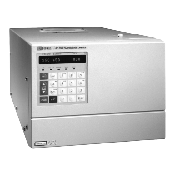
Operating Instructions RF-2000 3 Component Location and Function 3.1 Front View Description Function Control panel Performs setting and display. -
Page 15: Top Side And Right Side
Operating Instructions RF-2000 3.2 Top Side and Right Side Description Function Light source chamber cover Remove this cover when replacing the lamp. Cell cover Remove this cover when replacing the cell. Cell inlet tubing Marked with blue cover tubing. Cell outlet tubing 3.3 Bottom Side... -
Page 16: Rear View
Operating Instructions RF-2000 3.4 Rear View Description Function Horizontal direction adjusting Adjusts horizontal alignment of the lamp screw on replacement. 2/upper Vertical direction adjusting screw Adjusts vertical alignment of the lamp on replacement. 2/lower Lamp fixing screw Used to fix the lamp. -
Page 17: Installation
Operating Instructions RF-2000 4 Installation 4.1 Basic Installation Requirements To take full advantage of the RF-2000 performance capabilities and Warning: to ensure its operational stability over a long service life, verify that the selected installation site satisfies the following requirements. -
Page 18: Electrical Connections
Operating Instructions RF-2000 4.2 Electrical Connections When the power supply voltage is 220-230V~, operate the unit with Warning: the voltage setting of the power supply connector at the rear of this unit at 230Vac. When the power supply voltage is at 240V~, set the power supply connector at 240Vac. -
Page 19: Fluidic Connections
Operating Instructions RF-2000 4.3 Fluidic Connections 4.3.1 Connecting the Detector and the Column Typical connection between this equipment and the column is described in this section. Cut the piping tube (SUS Tube 1.6 x 0.3, standard accessory) at the length necessary for connecting the column outlet and the cell inlet pipe (pipe with blue tape) of this equipment. -
Page 20: Connecting The Recorder And The Integrator
4.4.2 Connecting with an Integrator Connect the integrator to the INTEGRATOR terminals in the external input/output terminals at the rear of the RF-2000. Connect the cable supplied with the integrator. Connect each terminal of the signal cable to the terminal block supplied with the... -
Page 21: Connecting A Drain Tube For Solvent Leakage
RF-2000 4.5 Connecting a Drain Tube for Solvent Leakage Each component in the RF-2000 is designed so that liquid leakage in the equipment is discharged from the liquid leak tube connection port at the right side or the lower front side of the equipment. Connect liquid leak tube if necessary. - Page 22 Operating Instructions RF-2000 • When the light source chamber cover shall be opened, be Warning: sure to turn OFF the power switch and disconnect the power cable from power supply. • It is very dangerous to touch the lamp by any mistake because high voltage, approx.
- Page 23 Operating Instructions RF-2000 Important: When doing this, do not touch the valve surface of the lamp. If touched, wipe off the surface with a gauze wet with ethanol (provided with the lamp), etc. If the lamp is lit with fingerprints on it, the fingerprints are burned and causes explosion of the lamp valve.
- Page 24 Operating Instructions RF-2000 Set the terminal of cable connected to the plus pole in the screw at the plus pole of the lamp and fix it with a knurled screw securely. Remount the light source chamber cover. When tightening the terminal at the plus pole with a...
-
Page 25: Adjusting The Xenon Lamp Alignment
Operating Instructions RF-2000 4.7 Adjusting the Xenon Lamp Alignment 4.7.1 Adjusting the light source position (coarse adjustment) Adjust the light source position for maximum equipment performance. Be sure to adjust the light source position during installation or replacement of the lamp. - Page 26 Connect a recorder to the 10mV RECORDER terminal of the RF-2000 (see section 7.1), and turn the power ON. Remove the flow cell from the RF-2000. Pour distilled water into the flow cell using the provided syringe. Make sure that no bubbles are present in the flow cell, and install the flow cell in the sample compartment (see "8.1...
- Page 27 Repeat the steps (8) and (9) so that the maximum value at the horizontal direction adjustment and that of the vertical direction adjustment become the same. In many cases, the value indicated on display of RF-2000 is more than (11) Stop recording by the recorder.
-
Page 28: Operation
Operating Instructions RF-2000 5 Operation 5.1 Precautions for Operation 1. Be sure the sample compartment cover is closed during Important: measurement. Measurement cannot be made correctly while the cover is opened. 2. Precautions to prevent clogging of the flow cell. Dusty or clogged flow cells are the most frequent causes of trouble in any detector. - Page 29 Operating Instructions RF-2000 5.2.2 Display unit The display unit consists of display screen and indicator lamps. Their descriptions and functions are as follows. Display or description Function EX (nm) Displays excitation wavelength (unit: nm) EM (nm) Displays emission wavelength (unit: nm)
- Page 30 Operating Instructions RF-2000 STD- func keys zero Auto zero key Pressing this key performs zero adjustment of emission intensity. ∆ ∆ ∆ ∆ zero shift ∇ ∇ ∇ ∇ Zero shift key Zero position on the recorder or integrator can be moved by pressing this key. It is moved upward by pressing the ∆...
- Page 31 Operating Instructions RF-2000 5.2.4 Setting excitation wavelength and emission wavelength EX(nm) EM(nm) Data <<350>> 1000.00 The value for excitation wavelength is blinking in the initial state to indicate that the excitation wavelength can be changed. Pressing the func key, emission wavelength becomes possible to be changed and pressing shift + back keys in this state, excitation wavelength becomes possible to be changed again.
- Page 32 Operating Instructions RF-2000 5.2.5 Setting sensitivity Setting procedure for sensitivity is as follows: Press shift + sens. The following is displayed. EX(nm) EM(nm) Data SENS <<2>> Sensitivity can be changed. Enter the desired set value with numerical key and press Enter.
- Page 33 Operating Instructions RF-2000 5.2.6 Setting recorder output range Procedure to set recorder output range is as follows: Press shift + range. The following is displayed. EX(nm) EM(nm) Data RANGE <<1>> Range can be changed. Enter a desired set value with numerical key and press Enter.
- Page 34 Operating Instructions RF-2000 5.2.7 Zero position adjustment for recorder Adjust the zero position of recorder according to the following procedure before starting measurement. Set the measuring range to a required value (refer to the previous item "Setting recorder output range").
-
Page 35: Operating Procedure In Spectrum Scanning Mode
Operating Instructions RF-2000 5.3 Operating Procedure in Spectrum Scanning Mode To seek the optimum excitation wavelength and emission wavelength, this unit is equipped with a spectrum scan function which can store two sample spectra and one background spectrum. This unit can output the spectrum of the excitation light. - Page 36 Operating Instructions RF-2000 5.3.2 Setting parameters Before starting scanning, set the scanning wavelength and scanning speed by AUX. FUNC. SCAN FILE Scan data file SPC TYPE Scan type (excitation, emission) EX SCAN BGN Excitation scan start wavelength EX SCAN END...
- Page 37 Operating Instructions RF-2000 Please note: If the output changes abruptly at the beginning or the end of the spectrum plot, the mark may not be recorded. Mark : approx. 4mV (INT) approx. 4mV (REC 10mV) approx. 0.4mV (REC 1mV) Output time T is as follows:...
-
Page 38: Creating And Executing A Time Program
Operating Instructions RF-2000 5.4 Creating and Executing a Time Program 5.4.1 Command list Commands which can be used for a time program are listed below: Command Description Setting range Remarks Excitation wavelength 0, 200 ~ 900 EXλ Emission wavelength 0, 200 ~ 900 EMλ... - Page 39 Operating Instructions RF-2000 In 5.1 minutes, sensitivity is set at 3 (Low). EX(nm) EM(nm) Data 5.10 GAIN Right after that, gain is set at 3 (x 16). EX(nm) EM(nm) Data 5.10 RESP Right after that, response is set at 2 (0.5s).
- Page 40 Operating Instructions RF-2000 Press Enter, and the following is displayed. EX(nm) EM(nm) Data TIME FUNC VALUE Time: Elapsed time from time program start (minute) Func: Command name Value: Set value If a time program is made, the following is displayed by pressing Enter again.
- Page 41 Operating Instructions RF-2000 5.4.3 Flow of setting Flow in setting a time program is shown below: EX(nm) EM(nm) Data <<350>> 1000.00 Press shift + edit. EX(nm) EM(nm) Data USED 32 LEFT Press Enter. EX(nm) EM(nm) Data <<TIME>> FUNC VALUE Enter with numerical keys.
- Page 42 Operating Instructions RF-2000 5.4.4 Scanning by program Example setting to execute scanning in 5 minutes and store data in file No. 2 using a program is shown below: Press CE to return to the initial screen. EX(nm) EM(nm) Data <<350>>...
- Page 43 Operating Instructions RF-2000 5.4.5 Deleting a step Display the step desired to be deleted and press shift + del. Display the step desired to be deleted. EX(nm) EM(nm) Data EX λ λ λ λ <<5.00>> Press shift + del. EX(nm)
-
Page 44: Additional Functions
Operating Instructions RF-2000 5.5 Additional Functions AUX. FUNC (AUXILIARY FUNCTION) is equipped in this instrument. 5.5.1 AUX. FUNC List Type Command Function TIME Displays the elapsed time while a time program is executed (when MONIT-TIME is set) SMPL EN Displays output from emission measurement sensor... - Page 45 Operating Instructions RF-2000 5.5.2 Setting procedure for AUX. FUNC TIME (Display of elapsed time of time program) EX(nm) EM(nm) Data TIME 100.00 This function displays the elapsed time from the program start while the time program is executed. However, this is displayed only when MONIT-TIME is set to 1 in AUX. FUNC.
- Page 46 Operating Instructions RF-2000 Magnification can be set as follows by combining with SENS (refer to section "5.2.5 Setting Sensitivity"). SENS Sensitivity magnifications 3 (LOW) approx. x 1 3 (LOW) approx. x 4 3 (LOW) approx. x 16 2 (MED) approx. x 32 2 (MED) approx.
- Page 47 Operating Instructions RF-2000 EX SCAN END (Setting of excitation scan end wavelength) EX(nm) EM(nm) Data EX SCAN END _ _ _ This function sets end wavelength for excitation scanning. Enter the desired end wavelength with a numeric key and press Enter (200 ~ 900).
- Page 48 Operating Instructions RF-2000 This function sets output speed of spectrum data to the recorder or integrator. Enter the desired set value with numeric key and press Enter. Set value Output speed 1 nm/s 5 nm/s 10 nm/s Please note: When recording to a recorder or an integrator is performed simultaneously with wavelength scanning, data is kept being output to the recorder or integrator regardless of this setting.
- Page 49 Operating Instructions RF-2000 MONIT-TIME (Setting of display of elapsed time of time program) EX(nm) EM(nm) Data MONIT-TIME This function displays the elapsed time from the time program start. It is displayed on the TIME screen in AUX. FUNC. Enter the desired set value with numeric key and press Enter.
- Page 50 Operating Instructions RF-2000 During scanning the excitation wavelength, this unit measures the spectrum without the division correction, because the corrected spectrum may not indicate the optimum excitation wavelength for analysis with this unit. XE TIME (Display of operating time of xenon lamp)
- Page 51 Operating Instructions RF-2000 To cancel this function, press shift and CE simultaneously. LAMP ADJUST (Lamp position adjustment) EX(nm) EM(nm) Data LAMP ADJUST Press Enter to enter the xenon lamp position adjusting mode and the light source intensity is displayed. For adjusting procedure, see section "4.7.1 Adjusting the light source position."...
-
Page 52: Performance Verification
Operating Instructions RF-2000 6 Performance Verification Inspection Environment Carrying out inspection measurements in an environment where the equipment is exposed to sudden changes of temperature or to air currents may affect the repeatability of the data. Inspections should be conducted in locations where changes of room temperature are less than 2°C. -
Page 53: Outline Of System Validation
Operating Instructions RF-2000 6.1 Outline of System Validation 6.1.1 Outline For the holistic validation of HPLC system, chromatographic analysis is performed under the analytical conditions specified by the manufacturer. The system status can be judged based on the obtained results. This is because the failure of the LC system may depend on the analytical conditions. - Page 54 Operating Instructions RF-2000 Check the connection of the units. Refer to the instruction manuals for details of the connection of each unit. Before installing the column, observe tubing connection of the LC system. Use tubing with 0.3mm I.D. or less from the outlet of auto injector to the column inlet and from the column outlet to the detector inlet.
-
Page 55: Repeatability Test Of Chromatographic Data (Gradient Lc)
Operating Instructions RF-2000 å − XA = (X1 + X2 + ..+ X4 + X5) / 5 %RSD = (SD / XA) * 100 X1 ..X5 Data Average Standard deviation %RSD Relative standard deviation Acceptance Criteria The acceptance criteria for the %RSD are shown below. - Page 56 50%, and column oven temperature to 40°C. Then start pump flow and temperature control. Then, confirm that the solvent comes out from the outlet tubing of the detector and no leak of solvent is observed at the connection. Set the parameters of RF-2000. EX (nm) GAIN...
- Page 57 Operating Instructions RF-2000 Calculate the average (X) of the data and %RSD using the equations as shown below. å − XA = (X1 + X2 + ..+ X4 + X5)/5 %RSD = (SD/XA) *100 X1..X5 Data Average Standard deviation...
-
Page 58: Control From External Equipment
Operating Instructions RF-2000 7 Control from External Equipment 7.1 Connecting External Input and Output Terminals Terminal name Explanation Note) EVENT OUT Outputs signals for relay contact (maximum rating: 50V, 0.1A). It is turned ON/OFF according to the program or the set value of EVENT parameter in AUX. - Page 59 Please note: A signal cable is provided with the RF-2000 as a standard accessory. In case two or more circuits or terminals shall be used, prepare cable separately.
-
Page 60: Control From External Equipment Via Rs-232C
RS-232C interface. This section explains how to connect the RF-2000 to an external system and how to operate the RF-2000 using external control. 7.2.1 Connecting external equipment The pins of RS-232C terminal at the rear panel of the RF-2000 are defined as shown in the figure below. Pin No. Signal name... - Page 61 EM(nm) Data CONNECT Press the Enter key. The RF-2000 is is now controlled from the external equipment via the RS-232C interface. In the remote control mode, the display of the RF-2000 indicates the excitation wavelength, the emission wavelength and the emission intensity, and RF-2000 outputs the analog signals of the emission intensity.
- Page 62 Operating Instructions RF-2000 Setting baud rate EX(nm) EM(nm) Data BAUD Set value Baud rate 300 bps 600 bps 1200 bps 2400 bps 4800 bps 9600 bps Enter the desired set value with the numeric key and press the Enter key.
- Page 63 • Stop the pump flow and record a new spectrum. The two spectra now exist in the RF-2000 spectra library as well as in individual spectra in two different storage locations within the detector.
-
Page 64: Operating Instructions Rf
Operating Instructions RF-2000 The detector reacts as if a Scan procedure was started. The result of the difference formation is saved to the RF-2000 spectra library again. This spectrum indicates the optimum emission or excitation value. Important: The basic requirement for forming difference spectra is the... - Page 65 Controlling the RF-2000 via the GynkoSoft data system is also possible. The device driver for the RF-2000 must be installed. The sensitivity can be set to "Low" (default) and "High" in GynkoSoft. The setting "Medium" is not supported by GynkoSoft.
-
Page 66: Maintenance
Operating Instructions RF-2000 8 Maintenance 8.1 Maintenance of Flow Cell When the xenon lamp is lit, the flow cell is irradiated by the Important: excitation light beam. Do not stave into the excitation light beam, while the xenon lamp is lit. - Page 67 Operating Instructions RF-2000 Flush out the nitric acid with distilled water. Replace with mobile phase. When the mobile phase used for analysis is not miscible with water, replace the flow lines with acetone and replace it with the mobile phase.
- Page 68 Operating Instructions RF-2000 Insert the inlet side Teflon packing (4 holes), flow cell, and outlet side Teflon packing (1 hole) into the flow cell holder. Be careful not to set the Teflon packings to wrong position. Screw in the outlet side knurled setscrew with the degree that no force is applied to the flow cell, the inlet side Teflon packing and the outlet side Teflon packing.
- Page 69 Operating Instructions RF-2000 8.1.4 Liquid leakage from flow cell A flow chart to find probable causes and counter measures for liquid leakage and clogging of pipes is shown in the following. Inspection start Is mobile phase liquid coming out of the...
- Page 70 Operating Instructions RF-2000 8.1.5 Countermeasure to LEAK error If the detector of the leak sensor is wet, even though there is no liquid leakage, LEAK error may be indicated. To recover this, open the sample compartment, suck the liquids in the drain pan by syringe and wipe the liquids on the leakage detector by cotton stick.
- Page 71 Operating Instructions RF-2000 Spiky noises are observed. The base line drifts in one direction and abruptly changes its drift direction. This symptom appears repeatedly. The base line is not stabilized. Excessive drifts or noises are observed. When the end of the flow cell outlet pipe is blocked, the pen moves greatly.
-
Page 72: Checking The Xenon Lamp
RATIO : 1 (fixed) Z WAVE Press the ZERO key of the RF-2000 to adjust the zero point. Move the emission wavelength at around 350nm so that the displayed value for data becomes around 700 ~ 800. Set the range so that the recorder pen varies in the range of 50 ~ 100 scales. - Page 73 Operating Instructions RF-2000 8.2.3 Operating time of xenon lamp Operating time of the xenon lamp is displayed in XE TIME in AUX. FUNC. The value is automatically accumulated while the lamp is lit on. Enter 0 and Enter to reset the time when replacing the lamp.
-
Page 74: Replacing The Fuse
Operating Instructions RF-2000 8.3 Replacing the Fuse This instrument uses two of the following fuses. Be sure to replace Warning: the fuses of the same type and capacity. for power supply: 220-240 VAC Part no. 706.072.0165221 250V 3.15AT Replace the blown fuse according to the following procedure. Be sure to use a fuse specified in the Accessories and Spare Parts list. -
Page 75: Changing The Set Power Supply Voltage
120Va.c 220V±10% 230Va.c 230V±10% 230Va.c 240V±10% 240Va.c Close the fuse holder cover until a clicking sound is heard. If the power supply voltage is 100 or 120 Va.c, a different fuse Warning: type must be used! Please contact Dionex Service. -
Page 76: Periodical Cleaning
200V If the power supply voltage is 100 or 120 Va.c, a different fuse Warning: type must be used! Please contact Dionex Service. Push in the rubber rid into the hole to seal the switch. 8.5 Periodical Cleaning If the cover or the panel of the unit is stained, wipe out dirt or dust with soft cloth or a... -
Page 77: Troubleshooting
Operating Instructions RF-2000 9 Troubleshooting 9.1 Summary of the Most Frequently Problems Symptom Probable cause Remedy 1. Power is not Fuse for power supply is Check the fuse in the fuse holder at the supplied even by blown. rear of this instrument and replace if it turning the power is blown. - Page 78 Operating Instructions RF-2000 Symptom Probable cause Remedy (cont.:) Bubbles in the flow cell Drive bubbles out of the flow cell. (See "8.1.8 Driving Bubbles out of Flow Cell 4. Improper S/N value and Liquid Leakage Test") (Signal level is low.) Check that the knurled setscrews are tightened.
- Page 79 Operating Instructions RF-2000 Symptom Probable cause Remedy 6. Raman peak of Impurities in water Use new distilled water. water is not displayed. Stains of the flow cell Clean the cell (See "8.1 Maintenance of Flow Cell") Replace the cell (See "8.1 Maintenance of Flow Cell")
- Page 80 Operating Instructions RF-2000 Symptom Probable cause Confirmation of Countermeasures cause Transient spiking Bubbles flowing With the flow cell 1) Apply pressure to through the cell tubing connected, the cell outlet side remove the cell, and lightly. Stop or check it under flow,...
- Page 81 Operating Instructions RF-2000 Symptom Probable cause Confirmation of Countermeasures cause Baseline wanders. The unit is in the 7) Change the presence of a location of the strong air current. instrument or place it in a protective environment. Noise occurs Mobile phase...
-
Page 82: List Of Error Messages
9.2.1 Errors which cannot be reset Turn the power of the instrument OFF and turn it ON again. If the error message persists, turn OFF the power and contact your Dionex Service Representative. RAM error It is displayed when something is wrong with the RAM. - Page 83 Operating Instructions RF-2000 No file error It is displayed when there is no data in the file in SPC PLOT or there is no data in the file 0 when the file 1 or 2 is specified (subtracted spectrum output).
- Page 84 Operating Instructions RF-2000 Wavelength calibration data error It is displayed when the wavelength calibration data entered in the unit is abnormal. EX(nm) EM(nm) Data ERR EX OFFSET Excitation side EX(nm) EM(nm) Data ERR EX W TABLE Excitation side EX(nm) EM(nm)
- Page 85 9.2.3 Error which can be reset with the shift + CE key. Rejecting key input When "CLOSE KEY" of the additional function is set or RF-2000 is controlled from a external equipment via RS-232C, any key input is rejected. To release these settings, press the CE key and the shift key simultaneously.
-
Page 86: Specifications
Operating Instructions RF-2000 10 Specifications Light source: 150W xenon lamp Light source chamber: Ozone self dissolving type lamp house Monochromators: Ion brazed holographic concave diffraction grating monochromators F/2. 4 for both excitation and emission sides Number of grooves: 900 lines/mm... - Page 87 Operating Instructions RF-2000 Filing: * Measurement condition One measurement condition can be stored. * Time program One time program can be stored. * Spectrum Three spectra can be stored. (However, they are not backed up when the power is turned OFF.)
-
Page 88: Standard Accessories
Teflon packing outlet (3 pcs) 706.228.3413681 Tools Screwdriver Other RF-2000 Operating Instructions 5820.5750 Certificate of compliance Label Ver.3 Important: When carrying out maintenance, be sure to use the parts described in the sections 10 and 11. Normal function of the system is not guaranteed when other parts are used.
Need help?
Do you have a question about the RF-2000 and is the answer not in the manual?
Questions and answers