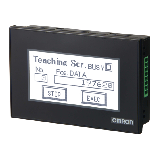
Omron NV3W-MR20L-V1 Operation Handbook

Omron NV3W-MR20L-V1 Operation Handbook

Nv-series pt

Advertisement

NV-series PT
Simple Operation
Handbook
- A case of connection to a CP1E PLC -
The NV3W-V1 is added.

Table of Contents

Preparation
Required Devices                 2
Wiring and Connection            4
Turning on the Power             6
Setting the CPIE Serial Port        8
Designing Screens
Creating New Screen Data        12
Creating Switch Parts            16
Creating Lamp Parts             19
Creating Data Parts              21
Creating Keyboard Screens       23
Creating Character Stings        26
Connecting with CP1E PLC
Transferring Screen Data         28
Advanced Usage
from CP1E                      34
Connecting PC and PLC via NV   35

Advertisement

Table of Contents
loading

Summary of Contents for Omron NV3W-MR20L-V1

  • Page 1: Table Of Contents

    NV-series PT Table of Contents Simple Operation Preparation Required Devices                 2 Handbook Wiring and Connection            4 Turning on the Power ...
  • Page 2: Required Devices

    NV3W-MRxx(x)-V1 NV3W-MGxx(x)-V1 NV4W-MRxx NV4W-MGxx - RS-232C type (5 VDC) - - RS-232C type (24 VDC) - NV3W-MR20L-V1 NV3W-MG20L-V1 NV4W-MR21 NV4W-MG21 - RS-232C type (24 VDC) - - RS-422A type (24 VDC) - NV3W-MR20-V1 NV3W-MG20-V1...
  • Page 3  * It cannot be purchased individually. The CX-One is a package that integrates the NV-Designer Ver.1.1 or higher  Support Software for OMRON PLCs and Note: The NV-Designer components. Ver.2.0 or higher is CX-One Lite Ver.4.x (4.03 or higher) ...
  • Page 4: Wiring And Connection

    Commercially available USB cable (Type A connector – Type B connector) XW2Z-200T-4 (2 m with 5-V Line) NV3W-MR20L-V1 Commercially available USB cable (Mini-B) Wiring for the CP1E AC power supply Wire for the CP1E AC power supply. 100 to 240 VAC, 50/60 Hz...
  • Page 5 NV-series PT Simple Operation Handbook  When the CP1E uses a 24-VDC power supply Wire the 24-VDC power supply as shown below. 24-VDC power supply Upper terminal block  When the NV3W-V1 (24-VDC type), the NV4W, or the NV3Q is connected with a RS-232C cable Wire the NV and the PLC as follows.
  • Page 6: Turning On The Power

    Turning on the Power Turn on the power to the CP1E. The power is also supplied to the NV through the RE-232C serial port on the CP1E. Turning on the power to the CP1E Turn on the power to the CP1E. The POWER LED indicator on the front of the CP1E lights in green.
  • Page 7: Displaying The Nv System Menu

    NV-series PT Simple Operation Handbook Displaying the NV System Menu The System Menu is the special screen that is used to configure the NV. Some settings such as touch switch adjustment can only be done on the System Menu. Accessing the System Menu Follow the steps below to access the System Menu.
  • Page 8: Setting The Cpie Serial Port

    Setting the CP1E Serial Port To have the NV and the CP1E communications, the both serial ports must have the same setting. Use the PLC programming tool CX-Programmer to set the communications on the CP1E. NV-CP1E communications setting example Both the NV and the CP1E support the high speed communication of 115,200 bps. Connect them in this baud rate.
  • Page 9 NV-series PT Simple Operation Handbook Online connection of the CX-Programmer and CP1E 1. Select Program – OMRON – CX-One – CX-Programmer – CX-Programmer from the Windows Start Menu to start the CX-Programmer. 2. Select PLC – Auto Online – Direct Online from the menu bar.
  • Page 10 Changing the CP1E operation mode into Program 1. Select PLC – Operation Mode – Program from the menu bar. 1) Confirm that stopping the ladder program do not cause any problem. Click the Yes Button. 2. The CP1E operation mode changes to the Program Mode. “Stopped”...
  • Page 11 NV-series PT Simple Operation Handbook 2. The PLC Settings Dialog Box appears . Select Options – Transfer from PLC from the menu bar. Click!! 3. The PLC settings for the CP1E are uploaded to the PC. Make the setting on the Built-in RS232C Port Tab Page as follows.
  • Page 12: Creating New Screen Data

    Create screen data by using the screen designing software NV-Designer. Starting the NV-Designer and creating a new project 1. Select Program – OMRON – CX-One – NV-Designer - NV-Designer from the Windows Start Menu,. 2. When the NV-Designer is started, the NV-Designer Dialog Box will be displayed.
  • Page 13 NV-series PT Simple Operation Handbook 4. Select the PLC model to connect. Click the Next Button. PLC Model: Select the PLC model to connect. 5. In the System Memory Area Field, set the Word Area and the Bit Area. Click the OK Button. System Memory Area: Specify the areas for controlling the NV in the PLC internal...
  • Page 14 6. The Main Window of the NV-Designer will be displayed. Double-click “0” in the Screen Manager. Base screen 0 and the Parts Library will open. Screen Manager Base Screen Parts Library Manu bar Toolbar Graphic bar Size-Position Double-click!! Note: The Size-Position Bar is a new function added to the NV-Designer Ver.2.0. Screen Manager Screens can be copied, pasted, cut, and deleted using the Screen Manager.
  • Page 15: Setting The Nv Communications

    NV-series PT Simple Operation Handbook Setting the NV Communications Set the NV - CP1E communications as the screen data. NV-CP1E communications setting example The CP1E communications was set as follows. Set the same for the NV communications. Mode: Host Link ...
  • Page 16: Creating Switch Parts

    Creating Switch Parts This and the following few pages describe the procedure to create parts on the screen, and confirming the NV-CP1E operations. Firstly, create a switch part that turns ON and OFF the specified bit in the PLC. Example of creating a switch part CIO 10.00 in the PLC is turned ON when the switch is pressed and turned OFF when it is released.
  • Page 17 NV-series PT Simple Operation Handbook Setting the function for the switch part Double-click the switch part. Select the Basic Setup Tab. Set the Operation Mode and ON/OFF Indication Fields. Operation Mode: It specifies the operation and the bit address in the PLC. ON/OFF Indication: Select either On to switch the ON/OFF indication or Off not to switch...
  • Page 18 2. Click the ON Button. Click the COPY from OFF Button. Then the setting for OFF is copied to ON. The two have the same setting. 1) ON/OFF: Click the ON Button. 2) Click the COPY from OFF Button. Click!! 3.
  • Page 19: Creating Lamp Parts

    NV-series PT Simple Operation Handbook Creating Lamp Parts A lamp part changes the display color when the specified bit in the PLC turns ON and OFF. Example of creating a lamp part The lamp changes color depending on the ON/OFF state of CIO 10.00 in the PLC. Bit OFF Bit ON The lamp is white when CIO10.00 is OFF.
  • Page 20 Setting the function for the lamp part Double-click the lamp part. Select the Basic Setup Tab. Set the ON/OFF Bit Field. Click the OK Button to close the dialog box. This completes creation of the lamp part. ON/OFF Bit: Set the bit address of the PLC.
  • Page 21: Creating Data Parts

    NV-series PT Simple Operation Handbook Creating Data Parts Create data parts which display the contents of addresses in the PLC on the PT screen. Data parts can be used for indication only (no entries allowed) or for changing the values from the keyboard screen as well. Example of creating a data part This data part indicates the value of D100 in the PLC in a decimal number.
  • Page 22 Setting the function for the data part Double-click the data part. Select the Basic Setup Tab. Make a necessary setting as shown below. Note: This example uses the default setting. Data to Display: Set Number of Digits, Data Format and Zero Suppression. Note: Select ASCII for Data Format when the data is indicated or entered as a character string.
  • Page 23: Creating Keyboard Screens

    NV-series PT Simple Operation Handbook Creating Keyboard Screens Create a keyboard screen to enter values for the data part. Example of creating a keyboard screen On this keyboard screen, you can enter decimal numbers and signs. Also you can confirm the values entered from the keyboard before they are set. Creating a keyboard screen 1.
  • Page 24 Creating a keyboard part Drag a keyboard part from the library and drop it at any desired space on the keyboard screen. 1) Use the Parts Library Standard (NV3W-V1). 2) Click the Parts Group Selection Button, and then select Keyboard. * Parts are displayed by type.
  • Page 25 NV-series PT Simple Operation Handbook Creating a data part Place a data part to show the value entered from the screen. Drag a data part from the library and drop it at any desired space on the keyboard screen. 1) Use the Parts Library Standard (NV3W-V1).
  • Page 26: Creating Character Stings

    Creating Character Strings This section explains the procedures to show texts or character strings on a screen. It also describes how to change the character attributes such as font, size and color. This way, the character string will stand out. Example of creating a character string In this example, the character string “Value”...
  • Page 27 NV-series PT Simple Operation Handbook  To show a picture image such as bitmap on the NV screen The NV-series PTs can display picture images such as bitmap images. You can paste images from the Windows clipboard to the NV screens. On the workspace of graphic software such as MS Paint, open an image file to show on the NV.
  • Page 28: Transferring Screen Data

    Transferring Screen Data Transfer the created screen data to the NV. Setting the transfer method 1. Select PT – Transfer – Transfer from the menu bar. Click!! 2. Select USB in the Communication Method Field. Click the OK Button to close the Transfer Data Dialog Box.
  • Page 29 NV-series PT Simple Operation Handbook Transferring the screen data 1. Set the transfer direction and data to transfer. Then transfer the data to the NV 1) Direction: 2) Data to Transfer: 3) Click the OK Button to Select NV-Designer -> NV. Select the All start transferring.
  • Page 30 Monitoring or changing the PLC parameters from the CX-Programmer After connecting the NV and CP1E, confirm NV screen operations. This step is explained in the next few pages. This subsection explains the Watch Window to monitor and change the contents of PLC addresses from the CX-Programmer. <...
  • Page 31: Checking Operation             31

    NV-series PT Simple Operation Handbook Checking Operation Check operation of the parts on an actual NV. Checking operation of the switch and lamp 1. While you press the RUN switch, 2. When you release your finger from the RUN switch, the lamp goes off.
  • Page 32: Switching Screens From Cp1E    32

    Switching Screens from CP1E Switch the NV screen from the CP1E PLC by using its system memory. Creating a new screen in an existing project Add a base screen to an existing project. The screen is used to confirm the screen switching operation.
  • Page 33 NV-series PT Simple Operation Handbook Setting and confirming the system memory 1. Select PT – NV Configuration from the menu bar. Click!! 2. Click the Basic Setup Tab. In the System Memory Area Field, you can set or confirm the allocated address.
  • Page 34: Changing Backlight Colors

    Changing Backlight Colors from CP1E Change the backlight color from the CP1E system memory. * The NV3Q-SWxx (color) can be set backlight ON and OFF only. Setting and confirming the system memory The backlight is controlled in the Bit Area of the system memory. Check the address allocated to the Bit Area in the System Memory Area Field on the Basic Setup Tab Page of the NV Configuration Dialog Box.
  • Page 35 NV-series PT Simple Operation Handbook Connecting PC and PLC via NV Connect the PC and the PLC via the NV to transfer the ladder programs from the PC (CX-Programmer) to the PLC and to monitor the PLC from the PC. Configuration example In this configuration, you can transfer the ladder programs and monitor the PLC from the CX-Programmer through the NV.
  • Page 36 Note: Do not use this document to operate the Unit. 2015 V411-E1-02 0715 (0110)

Table of Contents