
Related Manuals for McQuay MCW200


Summary of Contents for McQuay MCW200
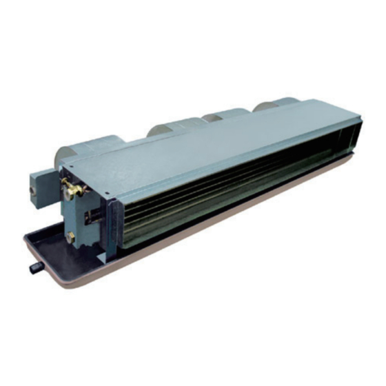
- Page 1 MCW - C/F/H - 2008 Technical Manual (50Hz) Ceiling Concealed Chilled Water Fan Coil Unit (50Hz) Models: MCW200 MCW300 MCW400 MCW600 MCW800 MCW1000 MCW1200 Air Flow: 112~2040m3/h Engineered for flexibility and performance.
-
Page 2: Table Of Contents
Wiring Diagrams ………………………………………………………………………………… 28 Installation ……………………………………………………………………………………… 30 Exploded View & Part List …………………………………………………………………… 32 Guide Specifications …………………………………………………………………………… 35 Note: Installation and maintenance are to be performed only by qualified personnel who are familiar with local codes and regulations, and experienced with this type of equipment. Caution: Sharp edges and coil surfaces are a potential injury hazard. Avoid contact with them. Warning: Moving machinery and electrical power hazard. May cause severe personal injury or death. Disconnect and lock off power before servicing equipment. “McQuay” is a registered trademark of McQuay International. All rights reserved throughout the world. © 2008 McQuay International “Bulletin illustrations cover the general appearance of McQuay International products at the time of publication and we reserve the right to make changes in design and construction at any time without notice.”... -
Page 3: Nomenclature
Description of Products A-Standard Drain Pan F1-Drain Pan Extended 100mm F2-Drain Pan Extended 200mm Material of Drain Pan A-Standard Material S-Stainless Steel Power Supply A-220V/1Ph/50Hz F-With Filter X-Without Filter B-Back Return Air Plenum D-Bottom Return Air Plenum X-Back return air plenum & bottom draw filter C-Without return air plenum Pipe Connection R-Facing Air Flow Right Hand L-Facing Air Flow Left Hand 0-0Pa External Static Pressure 3-30Pa External Static Pressure 6-60Pa External Static Pressure 8-80Pa External Static Pressure "-"-Original Design "A"-First Design Improve Electric Heater Power 10-10x100 W With Electric Heater C-3 Rows and 2 Pipes(3+0) H-4 Rows and 4 Pipes(3+1) F-4 Rows and 2 Pipes(4+0) Nominal Air Flow (CFM) (CFM,1CFM=1.7m3/h) McQuay Ceiling Concealed Chilled Water FCU... -
Page 4: Features
A boundary layer film of air adhering to the fin surface will insulate the fin surface and severally reduces the heat exchange efficiency. Mcquay slit fin design eliminates this boundary layer of air and creates continuous for best heat exchange efficiency. -
Page 5: Specifications
Specifications General Data MCW-C MODEL MCW200 MCW300 MCW400 MCW600 MCW800 MCW1000 MCW1200 1040 1420 1620 2040 HIGH 1200 1090 1140 1500 Air Flow MEDIUM 1020 0,30,60,80 EXTERNAL STATIC PRESSURE in.wg 0,0.12,0.24,0.32 2200 3200 4390 6160 7810 8830 10700 TOTAL COOLING... - Page 6 MCW-H MODEL MCW200 MCW300 MCW400 MCW600 MCW800 MCW1000 MCW1200 1010 1380 1570 2000 HIGH 1176 1070 1470 Air Flow MEDIUM 1010 0,30,60,80 EXTERNAL STATIC PRESSURE in.wg 0,0.12,0.24,0.32 2130 3100 4260 5980 7580 8570 10380 TOTAL COOLING CAPACITY Btu/h 7268 10578...
- Page 7 MCW-F MODEL MCW200 MCW300 MCW400 MCW600 MCW800 MCW1000 MCW1200 1010 1380 1570 2000 HIGH 1176 1070 1470 Air Flow MEDIUM 1010 0,30,60,80 EXTERNAL STATIC PRESSURE in.wg 0,0.12,0.24,0.32 2622 3418 5277 7185 8691 10261 12791 TOTAL COOLING CAPACITY Btu/h 8948 11661...
- Page 8 Components Data MCW-C/H/F MCW200 MCW300 MCW400 MCW600 MCW800 MCW1000 MCW1200 TYPE CENTRIFUGAL (BLADE: FORWARD) QUANTITY MATERIAL GALVANIZED STEEL DRIVE DIRECT DRIVE DIAMETER 6.25 LENGTH 7.875 TYPE SINGLE PHASE CAPACITOR RUNNING MOTOR QUANTITY IP/INSULATION GRADE IP20/E MATERIAL COPPER 9.52 DIAMETER TUBE 0.30 THICK- NESS 0.012 MATERIAL HYDROPHILIC ALUMINUM COIL 0.11...
-
Page 9: Sound Data
Sound Data MCW-C/H/F 30Pa 1/1 Octave Sound pressure level 1/1 Octave Sound pressure level Total Total (dBA, ref 20μPa) (dBA, ref 20μPa) Unit Speed dB (A) dB (A) 125 250 500 High Medium High Medium High Medium High Medium High Medium High 1000... -
Page 10: Performance Data-Cooling
1420 1820 1400 1720 1370 1590 1310 1400 1260 0.33 2190 1600 2080 1560 1940 1550 1800 1520 1660 1480 MCW200 0.42 14.8 2370 1740 2210 1700 2080 1660 1940 1640 1790 1610 0.51 21.6 2500 1830 2270 1800 2190... - Page 11 TOTAL SENSIBLE 0.24 2160 1580 2020 1560 1910 1520 1770 1460 0.33 2430 1780 2310 1730 2160 1720 2000 1690 MCW200 0.42 14.8 2630 1930 2460 1890 2310 1840 2160 1820 0.51 21.6 2780 2030 2740 2000 2430 1940 2260 1890 0.36...
- Page 12 1280 1640 1260 1550 1230 1430 1180 1260 1130 0.33 1970 1440 1870 1400 1750 1400 1620 1370 1490 1330 MCW200 0.42 14.8 2130 1570 1990 1530 1870 1490 1750 1480 1610 1450 0.51 21.6 2250 1650 2220 1620 1970...
- Page 13 1377 1765 1358 1668 1329 1542 1271 1358 1222 0.33 2124 1552 2018 1513 1882 1504 1746 1474 1610 1436 MCW200 0.42 14.8 2299 1688 2144 1649 2018 1610 1882 1591 1736 1562 0.51 21.6 2425 1775 2202 1746 2124...
- Page 14 1533 1959 1513 1853 1474 1717 1416 1513 1358 0.33 2357 1727 2241 1678 2095 1668 1940 1639 1785 1591 MCW200 0.42 14.8 2551 1872 2386 1833 2241 1785 2095 1765 1930 1736 0.51 21.6 2697 1969 2658 1940 2357...
- Page 15 1242 1591 1222 1504 1193 1387 1145 1222 1096 0.33 1911 1397 1814 1358 1698 1358 1571 1329 1445 1290 MCW200 0.42 14.8 2066 1523 1930 1484 1814 1445 1698 1436 1562 1407 0.51 21.6 2183 1601 2153 1571 1911...
- Page 16 2000 1500 1900 1400 1800 1400 1540 1300 0.33 0.96 2400 1700 2200 1600 2100 1584 1900 1596 1800 1495 MCW200 0.42 1.56 2600 1849 2400 1700 2200 1696 2100 1722 1900 1626 0.51 2.29 2700 1944 2500 1800 2400...
- Page 17 1738 2220 1671 2110 1553 2004 1560 1716 1444 0.33 0.96 2663 1891 2443 1774 2338 1758 1775 1995 1656 MCW200 0.42 1.56 2885 2051 2671 1890 2443 1880 2338 1911 2112 1808 0.51 2.29 3002 2157 3018 2000 2663...
- Page 18 1802 1350 1712 1257 1619 1261 1386 1166 0.33 0.96 2159 1530 1978 1436 1894 1431 1710 1439 1616 1343 MCW200 0.42 1.56 2337 1668 2161 1530 1978 1523 1894 1554 1709 1465 0.51 2.29 2430 1753 2445 1620 2159...
-
Page 19: Performance Data-Heating
0.24 1560 1970 2380 2790 3190 3600 4020 4420 4830 0.33 1670 2110 2550 2990 3430 3860 4300 4740 5190 MCW200 0.42 11.8 1740 2200 2650 3110 3580 4030 4490 4940 5410 0.51 17.3 1790 2260 2730 3190 3670 4140... - Page 20 ENTERING AIR: DB21ºC WATER ENTERING WATER TEMPERATUREºC W.P.D MODEL FLOW (kpa) (m³/h) 0.12 1180 1370 1820 1980 0.18 1160 1360 1800 1980 2180 MCW200 0.24 12.0 1170 1350 1780 1930 2160 2460 0.36 21.9 1150 1250 1730 1900 2150 2440 2640 0.12...
- Page 21 0.24 1701 2148 2595 3042 3478 3925 4383 4819 5267 0.33 1821 2301 2780 3260 3740 4209 4689 5168 5659 MCW200 0.42 1897 2399 2890 3391 3904 4394 4896 5386 5899 0.51 1952 2464 2977 3478 4002 4514 5027 5539 6052 0.36...
-
Page 22: Air Flow Vs Esp Curve
Air Flow vs ESP Curve 1-0Pa 2-30Pa 3-60Pa 4-80Pa MCW200 MCW300 ESP, Pa ESP, Pa MCW400 MCW600 1000 1800 1600 1400 1200 1000 10 20 30 40 50 60 70 80 90 10 20 30 40 50 60 70 80 90... -
Page 23: Operating Limits
MCW1200 2600 2400 2200 2000 1800 1600 1400 10 20 30 40 50 60 70 80 90 ESP, Pa Operating Limits Operating Limits MCW-C/H/F Water Circuit Max. Water side pressure 1.6MPa Min. Entering water temperature 3ºC (cooling) Max. Entering water temperature 80ºC (heating) Power supply Operating voltage limits ± 0% Volt Operating frequency limits ±2Hz ... -
Page 24: Water Flow Rate Vs Pressure Drop Chart
Water Flow Rate vs Pressure Drop Chart MCW-C 3 Rows Coil Unit Water Pressure Drop Curve MCW600 MCW400 MCW800 MCW200 MCW1200 MCW300 MCW1000 MCW-H 1 Row Coil System Unit Water Pressure Drop Curve MCW200 MCW300 MCW400 MCW1200 MCW600 MCW800 MCW1000... - Page 25 MCW-F...
-
Page 26: Outlines And Dimensions
Outlines and Dimensions MCW-C/H/F Number of UNIT SIZE Standard 100mm extension Drain pan drain pa n Fans MCW200C MCW300C 1014 1114 MCW400C MCW600C 1214 1314 1005 MOUNTING HOLE MCW800C 1464 1564 1198 1237 1255 4-10*16 MCW1000C 1564 1664 1298 1337 1355 MCW1200C 1824... - Page 27 UNIT Number of Standard 100mm extension Drain pan Fans Drain pan MCW200H MCW300H MCW400H 1014 1114 Mounting Hole MCW600H 1214 1314 1005 4-10*16 MCW800H 1464 1564 1198 1237 1255 MCW1000H 1564 1664 1298 1337 1355 MCW1200H 1824 1924 1558 1597 1615 Condensate Drain R 3/4...
-
Page 28: Electrical Data
Electrical Data MCW-C/H/F MODEL MCW200 MCW300 MCW400 MCW600 MCW800 MCW1000 MCW1200 INSULATION GRADE/IP E/20 POWER SOURCE V/Ph/Hz 220~240/1/50 RATED INPUT POWER MOTOR RATED RUNNING CURRENT 0.10 0.15 0.20 0.30 0.47 0.48 0.60 POLES INSULATION GRADE/IP E/20 POWER SOURCE V/Ph/Hz 220~240/1/50... -
Page 29: Wiring Diagrams
Wiring Diagrams Wiring(C/H/F) Electrical wiring connection must be done according to the wiring diagram on the unit. The unit must be GROUNDED to the earth system of the building. All field wiring must be installed in accordance with the national wiring regulation and Fire Department regulation. FOR MODEL: MCW200 MCW300 MCW400 MCW600 (0Pa and 30Pa) WIRING ORANGE BLACK BROWN BLACK YELLOW FAN SPEED SWITCH... - Page 30 FOR MODEL: MCW200 MCW300 MCW400 MCW600 (60Pa and 80Pa) WIRING ORANGE BLACK BROWN BLACK YELLOW FAN SPEED SWITCH POWER BLUE SOURCE MAIN SWITCH NOTE: FIELD WIRING MF: FAN SPEED MEDIUM M~: FAN MOTOR HF: FAN SPEED HIGH LF: FAN SPEED LOW SHF: FAN SPEED SUPER HIGH 60Pa: LF—Low Speed MF—Medium Speed HF—High Speed...
-
Page 31: Installation
Installation Receiving All units leaving the McQuay plant have been inspected to ensure the shipment of high quality products and reasonable means are utilized to properly pack the fan coil units to protect them in transit. Carefully inspect all shipments immediately upon delivery. When damage is visible, note this fact on the carrier’s freight bill and request that the carrier sends a representative to inspect the damage. This may be done by telephone or in person, but should always be confirmed in writing. The shipment should be unpacked in the presence of the agent so that the damage or loss can be ... - Page 32 Fig.2 WITH AND WITHOUT PLENUM FORM: Terminal block Ceiling access Panel with air return Discharge air Return air Fig.3 DETAIL A: EXP ANSION SCREW HANGING ROD HANGING ROD FANCOIL FLAT WASHER Air Duct Connection Circulatory air pressure drop should be within External Static Pressure Galvanized steel air ducts are suitable Make sure there is no leak of air. Air duct should e fireproof, refer to concerned country national and local regulations. Pipe Connection Using suitable fittings as water pipe connections.
-
Page 33: Exploded View & Part List
Exploded View & Part List PART NUMBER DESCRIPTION MODEL SELECTION M50014063206 TERMINAL BOX SUPPORT TMCW200-1200C/F/H M50064063434 TERMINAL BOX COVER MCW200-1200C/F/H A04114012928 TERMINAL BLOCK MCW200-1200C/F/H need selection BLOWER CENTRIFUGAL need selection need selection need selection DRIANPAN need selection M01014060309 DRAIN GUIDE PLATE MCW200C/H/F M01014060312 DRAIN GUIDE PLATE MCW300C/H/F M01014060315 DRAIN GUIDE PLATE MCW400C/H/F M01014060318 DRAIN GUIDE PLATE MCW600C/H/F M01014060321 DRAIN GUIDE PLATE ... - Page 34 DESCRIPTION M03029000980 BLOWER CENTRIFUGAL SYP 60/200J-L M03029000981 BLOWER CENTRIFUGAL SYP 60/200J-R Item5.Drainpan DESCRIPTION NOTE MODEL SELECTION QUANTITY M50014063167 DRAINPAN STANDARD LENGTH.PE INSULATION MCW200C/H/F M50014063168 DRAINPAN STANDARD LENGTH.PE INSULATION MCW300C/H/F M50014063169 DRAINPAN STANDARD LENGTH.PE INSULATION MCW400C/H/F M50014063170 DRAINPAN STANDARD LENGTH.PE INSULATION MCW600C/H/F M50014063171 DRAINPAN STANDARD LENGTH.PE INSULATION MCW800C/H/F M50014063172 DRAINPAN STANDARD LENGTH.PE INSULATION MCW1000C/H/F M50014063173 DRAINPAN STANDARD LENGTH.PE INSULATION MCW1200C/H/F M50014063738 DRAINPAN ...
- Page 35 Item 10.Motor MOTOR: 220V/1Ph/50H STATIC PRES- MODEL DESCRIPTION PART NUMBER DESCRIPTION SURRE 0 Pa M03034065037 MOTOR, YDK7-6B4 MCW200 C/H/F 30 Pa M03034065041 MOTOR, YDK10-4B4 60/80 Pa M03034065045 MOTOR, YDK22-4B4 0 Pa M03034065038 MOTOR, YDK10-6B4 MCW300 C/H/F 30 Pa M03034065042 MOTOR, YDK16-4B4 60/80 Pa M03034065046 MOTOR, YDK32-4B4 0 Pa M03034065039 MOTOR, YSK16-6B4 MCW400 C/H/F 30 Pa M03034065043 MOTOR, YSK20-4B4...
-
Page 36: Guide Specifications
Guide Specifications Unit Description Factory-assembled, horizontal, blow-thru type, galvanized casing, ceiling ducted fan coil unit is complete with water coil, fans, motors, drain pan, filters and all required wiring, with full access to internal components. Quality Assurance Each coil is factory tested for leakage at 3.3MPa air pressure with coil submerged in water. Each unit and its moving components (fans and motors) are factory computer-tested and recorded after unit is complete and before it is packed. Component Specifications 1.Casing: Construction is of 0.8mm thickness galvanized steel, lined on the inside with 5mm PE thermal and acoustical insulation. Return air plenum is lined with 5mm PE foam and has a 30mm collar for return duct connection. Supply duct connection also has a 30mm long collar. Removable bottom panel is provided for access to the fan/motor assembly. 2. Coil: Standard unit is equipped with a 3-row (C series), 4-row (F series) or 3+1 rows (H series) coil for installation in a 2-pipe (C and F series) or 4-pipe (H series) system. Coil has 3/8 inch seamless copper tubes, slit type fins hydrophilic aluminum bonded to the tubes by mechanical expansion. Each coil has a manual air vent and ... - Page 37 ©2008 McQuay International +1 (800) 432-1342 www.mcquay.com While utmost care is taken in ensuring that all details in the publication are correct at the time of going to press, we are constantly striving for improvement and therefore reserve the right to alter model specifications and equipment without notice. Details of specifications and equipment are also subject to change to suit local conditions and requirements and not all models are available in every market.
Need help?
Do you have a question about the MCW200 and is the answer not in the manual?
Questions and answers