Table of Contents
Advertisement
Quick Links
Advertisement
Table of Contents

Related Manuals for McQuay Magnitude WMC 145SBS - 400DBS


Summary of Contents for McQuay Magnitude WMC 145SBS - 400DBS
- Page 1 Operating & Maintenance Manual OMM 1008-1 Group: Chiller Part Number: 332830001 Effective: November 17, 2010 Supersedes: April 2010 Magnitude™ Magnetic Bearing Chillers Model WMC 145SBS – 400DBS OITS Software Version: 2.01.01 Control Software Version: WMCU3UU02B...
-
Page 2: Table Of Contents
Manufactured in an ISO Certified Facility ©2010 McQuay International. Illustrations and data cover the McQuay International product at the time of publication and we reserve the right to make changes in design and construction at anytime without notice. ™® The following are trademarks or registered trademarks of their respective companies: BACnet from ASHRAE;... -
Page 3: Introduction
McQuay disclaims any liability resulting from any interference or for the correction thereof. Temperature and humidity considerations The unit controllers are designed to operate within an ambient temperature range 20°F to 130°F... -
Page 4: Features Of The Control Panel
Features of the Control Panel • Control of leaving chilled water within a ±0.2°F (±0.1°C) tolerance. • Display of the following temperatures and pressures on a 15-inch Super VGA touch-screen operator interface • Entering and leaving chilled water temperature • Enter and leaving condenser water temperature •... -
Page 5: Definitions
Definitions Active Setpoint The active setpoint is the parameter setting in effect at any given moment. This variation can occur on setpoints that can be altered during normal operation. Resetting the chilled water leaving temperature setpoint by one of several methods such as return water temperature is an example. Active Capacity Limit The active capacity setpoint is the setting in effect at any given moment. - Page 6 Load Limit An external signal from the keypad, the BAS, or a 4-20 ma signal that limits the compressor loading to a designated percent of full load. Used to limit unit power input. Load Balance Load balance is a technique that equally distributes the total unit load between two or more running compressors.
- Page 7 Setpoint Suction Superheat Suction superheat is calculated for each circuit using the following equation: Suction Superheat = Suction Temperature – Evaporator Saturated Temperature Stageup/Stagedown Delta-T Staging is the act of starting or stopping a compressor or fan when another is still operating. Startup and Stop is the act of starting the first compressor or fan and stopping the last compressor or fan.
-
Page 8: General Description
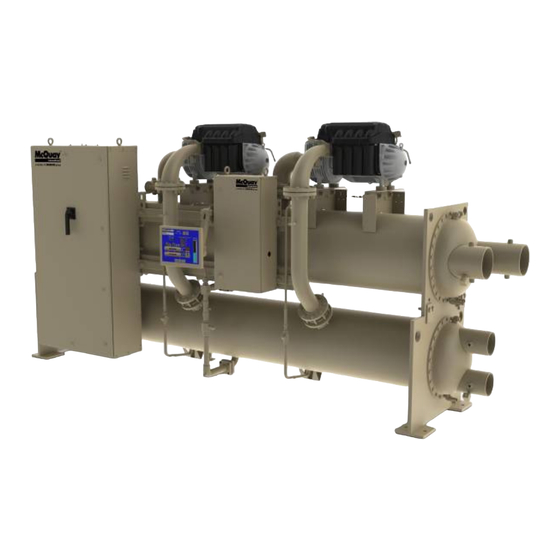
General Description Major Components Figure 1, Major Component Location Compressor #1 Compressor #2 Unit Control Panel Evaporator Relief Valve, Behind Panel Operator Interface Panel (OITS) Condenser Power Panel Control Panel Relief Valves (Front End Box) Behind Panel Electronic Expansion Valve General Description The centrifugal MicroTech ΙΙ... -
Page 9: Control Panel
Control Panel Figure 2, Control Panel EXV Board Field Wiring Knockouts Terminal Board TB UTB1 for Field Wiring Connections On/Off Switches Controller UNIT COMP #1 COMP #2 OITS PC Universal Communication Module Emergency Shutdown Switch, Outside Panel Comp #1 I/O Comp #2 I/O The unit controller, the OITS microprocessor, the unit and compressor on/off switches and other minor components are mounted in the control panel. -
Page 10: Use With On-Site Generators
The necessary procedure for reconnecting power from the generator back to the utility grid is show below. These procedures are not peculiar to McQuay units only, but should be observed for any chiller manufacturer. 1. Set the generator to always run five minutes longer than the unit start-to-start timer, which could be set from 15 to 60 minutes. - Page 11 Table 1, pLAN address and DIP Switch Settings for Controllers Using pLAN. Chiller Comp 1 Comp 2 Unit Reserved Operator Reserved Controller Controller Controller Interface (2) Dec. Bin. 100000 010000 101000 011000 000100 Dec. Bin. 100100 010100 101100 011100 000010 NOTES for pLAN multi-chiller communication setup: Two Magnitude units can be interconnected.
-
Page 12: Operating Limits
Operator Interface Touch Screen (OITS) Settings Settings for any type of linked multiple compressor operation must be made to the MicroTech II controller. Settings on a dual compressor unit are made in the factory prior to shipment, but must be verified in the field before startup. - Page 13 This is especially true of an advanced design such as the McQuay Magnitude chiller that features variable compressor speed. It is an engineering fact that as the compressor discharge pressure is reduced, the amount of power to pump a given amount of gas also is reduced.
-
Page 14: Operating The Control System
Operating the Control System Interface Panel On/Off The Operator Interface Panel is turned on and off with a switch located at the lower front of the panel. Screen control buttons are located to either side of it and elicit on-screen prompts when pressed. The screen is equipped with a screen saver that blackens the screen. -
Page 15: Component Failure
3. Press the ACKNOWLEDGE button to recognize the alarm. 4. Correct the condition causing the alarm. 5. Press the CLEAR button to clear the alarm from the controller. If the fault condition is not fixed, the alarm will continue to be on and the unit will not be able to be restarted. Component Failure Chiller Operation without the Operator Interface Panel The Operator Interface Touch Screen communicates with the unit controller, displaying data and transmitting... -
Page 16: Navigating
Keypad A 4-line by 20-character/line liquid crystal display and 6-button keypad is mounted on the controller. Its layout is shown below. Figure 4, Controller Keypad Red Alarm Light Behind MENU Key Key-to-Screen Pathway Air Condit ioning < ALARM < VIEW <... -
Page 17: Menu Screens
c) After selecting this second level, the desired screen can be acquired using the arrow keys. A typical final screen is shown below. Pressing the MENU key from any menu screen will automatically return you to the MENU mode. Figure 5, Typical Menu Display and Keypad Layout MENU Key Air Conditioning VIEW UNIT STATUS... -
Page 18: Unit Controller
Unit Controller Table 2, Unit Controller, Analog Inputs Description Signal Source Range Reset of Leaving Water Temperature 4-20 mA Current 0-(10 to 80° F) Entering Evaporator Water NTC Thermistor (10k@25° C) -58 to 212° F Temperature Entering Condenser Water NTC Thermistor (10k@25° C) -58 to 212°... - Page 19 At power-up the slave node checks if the master node is operational and if so, it sets its copy of the setpoint equal to the master’s. Otherwise, the setpoint remains unchanged. During normal operation, any time the master setpoint changes, the slave is updated as well. The PW (password) column indicates the password that must be active in order to change the setpoint.
- Page 20 Description Default Range Type Stage Up Time 2 min 1 to 60 min Stage Down Time 5 min 1 to 60 min Stage Differential (Temp) 3.0 °F 1.0 to 10.0 °F Stage Differential (Lift) 6.0 psi 1.0 to 20.0 psi Stage #1 On (Temp) 70 °F 40 to 120 °F...
-
Page 21: Faults, Problems, Warnings
Faults, Problems, Warnings Faults (Equipment Protection Shutdowns) There are no Unit protection shutdown alarms; all such alarms are handled through the compressor controllers. Problems (Limit Alarms) The following alarms limit operation of the chiller in some way as described in the Action Taken column. Table 7, Controller Limit Alarms Description Occurs When:... - Page 22 1. Cool LWT setpoint 2. Max Reset Delta T setpoint 3. Start Reset Delta T setpoint Reset is accomplished by changing the Active Leaving Water variable from the (Cool LWT setpoint) to the (Cool LWT setpoint + Max Reset Delta T setpoint) when the evaporator (return – leaving) water temperature delta varies from the (Start Reset Delta T setpoint) to 0.
-
Page 23: Compressor Controller
Compressor Controller The compressor controller's primary function is controlling and protecting the compressor. No setpoints are input to it. There is one compressor controller for each compressor on the unit. The compressor controller receives, processes, and sends data to the unit controller, the compressor on-board microprocessors and to external devices. -
Page 24: Compressor Faults, Problems, Warnings
Compressor Faults, Problems, Warnings Faults (Equipment Protection Shutdowns) Equipment protection faults cause rapid compressor shutdown. The compressor is stopped immediately (if the compressor was running). The following table identifies each alarm, gives the condition that causes the alarm to occur, and states the action taken because of the alarm. -
Page 25: Compressor Control Functions
Warnings Warnings advise that a non-catastrophic problem exists, such as failed temperature sensor that provides a signal for information, not control purposes. There are no Warnings associated with the compressor controllers. Compressor Control Functions Each compressor determines if it has reached its maximum capacity (or maximum allowed capacity) and if so, set its Full Load flag. - Page 26 Configuration Rules 1. Each standby compressor must have a sequence number greater than or equal to all non-standby compressors for which it is in standby. 2. All compressors in an “efficiency priority” or “pump priority” group must be set to the same sequence number.
- Page 27 MANUAL. Of the following limits, the one creating the lowest amp limit is in effect. The resulting present limit value for compressor current is stored in the Active Demand Limit variable. Low Evaporator Pressure If the evaporator pressure drops below the Low Evaporator Pressure – Inhibit setpoint, the unit will inhibit capacity increase.
-
Page 28: Compressor On-Board Controllers
Compressor On-Board Controllers Each compressor is equipped with microprocessor controllers and sensors that provide control and data acquisition. The data is transmitted to other controllers and the OITS via the multi-unit communication network. The on-board controllers consist of: • Compressor Controller: the compressor controller is the central processor of the compressor. It is continually updated with critical data from the motor/bearing controller and external sensors. - Page 29 Figure 8, Field Wiring Diagram MICROTECH CONTROL BOXTERMINALS (115V) (24V) UTB1 * REMOTE ON/OFF POWER (NOTE5) NOTE7 NEUTRAL * NOTE10 MODESWITCH * NOTE8 * COOLING TOWER FOURTH STAGE STARTER NOTE11 (NOTE6) * CHILLED * NOTE10 EVAP. EWI-2 WATER DELTA P. PUMP ORFLOW * COOLING...
-
Page 30: Operator Interface Touch Screen
Minimum wire size for 115 VAC is 12 ga. for a maximum length of 50 feet. If greater than 50 feet refer to McQuay for recommended wire size minimum. Wire size for 24 VAC is 18 ga. All wiring to be installed as NEC Class 1 wiring system. - Page 31 Figure 9 illustrates the arrangement of the various screens available on the OITS. A few minutes practice on an actual OITS should provide an acceptable level of confidence in navigating through the screens. Figure 9, OITS Screen Layout SET SCREENS HISTORY SCREENS HOME...
-
Page 32: Screen Descriptions
Screen Descriptions Figure 10, Home View Screen VIEW Screens View screens are used for looking at unit status and conditions. Home View Screen The Home View Screen shows the basic operating condition of the chiller and is the screen that is normally left on. - Page 33 from compressor controller RUN Load Vanes-Manual Speed RUN Hold Vanes-Manual Speed RUN Unload Vanes-Manual Speed RUN Load Speed-Manual Vanes RUN Hold Speed-Manual Vanes RUN Unload Speed-Manual Vanes RUN Unload Vanes-Lag Start RUN Hold Vanes-Evap Press RUN Unload Vanes-Evap Press RUN Unload Vanes-Soft Load RUN Hold Vanes-Soft Load Overrides water temperature command RUN Load Vanes-Disch Temp...
- Page 34 Figure 11, Detail View Screen Data for one compressor is shown at a time on this screen. Pressing the COMPRESSOR button in the screen lower-left hand corner will toggle between #1 and #2 compressor. Pressing the VIEW button on the bottom of the Home View screen accesses the Detail View Screen shown above.
- Page 35 Figure 12, View Menu This View Menu is accessed by pressing the MENU button from the Detail View Screen. The menu screen accesses several informational screens as shown in the above figure. Figure 13, View Compressor State Screen For example, pressing the Compressor-State button on the Menu screen in Figure 12 will display the screen shown in Figure 13 on the right side of both the Menu screen and the Detail View screen.
- Page 36 Figure 14, View Compressor Input/Output Status Pressing the I/O button adjacent to the compressor on the VIEW-MENU screen will access the screen shown in Figure 14. It is superimposed on the right side of the Detail View Screen. It gives the status of the compressor digital inputs and outputs.
-
Page 37: Set Screens
Panel is unavailable, the unit controller can be used to change setpoints.) Appropriate setpoints are factory set and checked by McQuay Factory Service or Factory Authorized Service Company during commissioning. However, adjustments and changes are often required to meet job conditions. Certain settings involving pumps and tower operation are field set. - Page 38 Figure 17, A Typical SETPOINT Screen Unit Status Compressor Status Setpoint Description Range of Settings Numeric Keypad Setpoint Setpoints Selection Initiate Setpoint Action Buttons Change Groups Buttons Button The above figure shows the Water screen with Leaving Water Temp setpoint selected. The various setpoint groups are in a column on the right side of the screen.
- Page 39 3. Press the CHANGE button indicating that you wish to change a setpoint value. The KEYBOARD screen will be turned on automatically to facilitate entering the password. • O = Operator level password is 100 • M = Manager level password is 2001 •...
- Page 40 TIMERS Setpoint Figure 18, TIMERS Setpoint Screen Table 17, TIMER Setpoints Pass- Description Default Range Comments word 0 to 999 Time compressor must load (without unloading) before Full Load Timer 300 sec sec. vanes are considered fully open. 10 to 240 Maximum time allowed before interlock confirmation Interlock Timer 10 sec...
- Page 41 ALARMS Setpoint Figure 19, ALARMS Setpoint Screen Table 18, ALARM Setpoints Pass- Description Default Range Comments word Condenser Freeze Minimum cond. sat. temp. to start pump 34.0 °F -9.0 to 45.0 °F Evaporator Freeze 34.0 °F -9.0 to 45.0 °F Minimum evap.
- Page 42 Cooling Tower Bypass VALVE Settings Figure 20, Tower Bypass VALVE Setpoint Screen Table 19, Tower Bypass VALVE Setpoints (See page 44 for complete explanation.) Pass- Description Default Range Comments word Slope Gain 10 to 99 Control gain for temperature (or lift) slope Error Gain 10 to 99 Control gain for temperature (or lift) error...
- Page 43 Cooling TOWER Fan Settings Figure 21, Cooling TOWER Fan Setpoint Screen (See page 44 for complete explanation.) Table 20, Tower Fan Settings Pass- Description Default Range Comments word Stage #4 On (Lift) 35 psi 10 to 130 psi Lift pressure for fan stage #1 on Stage #3 On (Lift) 45 psi 10 to 130 psi...
- Page 44 Explanation of Tower Control Settings The MicroTech II controller can control cooling tower fan stages, a tower bypass valve, and/or a tower fan VFD if the chiller has a dedicated cooling tower. The Tower Bypass Valve position will always control the Tower Fan Staging if Valve Setpoint or Stage Setpoint is selected.
- Page 45 2. Tower Fan Staging With Bypass Valve Controlling Minimum EWT (VALVE SP). 1) TOWER SETPOINT Screen SP1. Select TEMP if control is based on condenser EWT or LIFT if based on compressor lift expressed in pressure. SP2. Select Valve SP for control of bypass valve based on temperature or lift. SP3.
- Page 46 If LIFT was selected for fan control, use: SP3, Set the VALVE TARGET (setpoint), usually 30 psi below the minimum fan stage setpoint established in TOWER SP15. This keeps full flow through the tower until the last fan is staged off. SP5, Set VALVE DEADBAND, the default of 6 psi is a recommended initial setting.
- Page 47 MOTOR Setpoint Screen Figure 23, MOTOR Setpoint Screen Table 21, MOTOR Setpoint Settings Pass- Description Default Range Comments word Nominal Capacity 0 to 9999 Tons Determines when to shut off a compressor 0.1 to 5.0 Inhibits loading if LWT change exceeds the setpoint Maximum LWT Rate value.
- Page 48 MODES Setpoints Figure 24, MODES Setpoint Screen NOTE: Gray setpoints are not used with Magnitude chillers. Table 22, MODES Setpoint Settings Pass- Description Default Range Comments word Comp # 2 Stage 1,2, … (# of Sets sequence number for # 2 compressor, if 1 it is Sequence Compressors) always first to start, if 2 is always second (Note 1)
- Page 49 WATER Setpoints Figure 25, WATER Setpoint Screen Table 23, WATER Setpoint Settings Pass- Description Default Range Comments word Set the maximum reset that can occur, in Max Reset Delta-T 0.0°F 0.0 to 20.0 °F degrees F if LWT reset is selected or max reset at 20 mA input if 4-20 mA is selected in SP7 Sets the evap delta-T above which Return reset Start Reset Delta-T...
-
Page 50: Service Screen
1 and 2 are compressor controllers, 5 is the unit controller and 7 is the interface panel. pLAN Comm is used for setting up multiple chillers and is set at startup by the McQuay startup technician as is LOAD UCM. -
Page 51: History Screens
HISTORY Screens Figure 27, History Trend Graph The Trend History Overview allows the user to view the various parameters listed on the right side of the screen. The temperature scale in °F is on the left. Pressure in psi and % RLA are represented by the right- hand scale. -
Page 52: Download Data
Figure 28, Alarm History/Floppy Download The Alarm History lists the alarms with the most current on top with date stamp, action taken and the cause of the alarm. It is accessed from the history screen by pressing HISTORY again. The alarms have a color code as follows: •... -
Page 53: Active Alarm Screen
ACTIVE ALARM Screen Figure 29, Active Alarms The Active Alarm screen is only accessible when an active alarm exists on the unit. Pressing the red alarm signal on any screen will access this screen. It can also be accessed from the SERVICE screen by pressing the dark blue button (where the Alarm indicator normally appears). - Page 54 Figure 30, Keyboard The keyboard is only used to enter the password when attempting to enter or change a setpoint. Input the number (100 for operator, 2001 for manager level) and press Enter to enter the password. The screen will automatically revert back to the previous Set screen.
-
Page 55: Unit Controller Menu Screens
Unit Controller Menu Screens The unit controller, located in the control panel adjacent to the OITS, is the only controller used by the unit operator. In addition to unit functions, most compressor parameters are viewable on it, and all setpoints can be accessed from it. -
Page 56: Menu Matrix
Menu Structure (Scrolled) As an alternate to selecting screens with the menu function, it is be possible to scroll through all of them with the 4 arrow keys. For this use, the screens are arranged logically in a matrix as shown in Figure 31. Menu Matrix Figure 31, Unit Controller Menu Matrix View... - Page 57 Table Continued VIEW ALARMS SET SETPOINTS PASSWORD Alarm Log: 01 SET UNIT SPs SET COMP#1 SPs (1) SET COMP#2 SPs (1) SET ALARM LMTs (1) SET TOWER SPs (1) SET PASSWORD description Unit Enable = OFF Demand Limit=OFF Demand Limit=OFF LowEvPrHold=33psi TowerControl=(type?) Enter...
- Page 58 Selection can then be made by using the LEFT/RIGHT keys to move between columns and the UP/DOWN keys to move between rows. If the VIEW COMP#2 (3) screen is being viewed and the RIGHT arrow key is pressed, the display will show VIEW EVAP.
- Page 59 VIEW UNIT WATER° ° ° ° F(3) Water Flow Rates Evap XXXXX GPM Cond XXXXX GPM View Refrigerant Status VIEW UNIT REFRG (1) ° ° ° ° F Sat Evap XXX.X XX.X Sat Cond XXX.X XX.X VIEW UNIT REFRG (2) Suct Line = XXX.X°...
- Page 60 VIEW COMP#N (2)psi Cond Press =XXXX Evap Press =XXXX Lift Press = XXX VIEW COMP#N (3) psi WMC Compressor Oilless Design (blank menu) VIEW COMP#N (4) °F Cavity Temp=XXX.X°F Invert Temp=XXX.X°C Lift Temp = XX.X°F VIEW COMP#N (5) °F Temp Suction XXX.X XX.X DischargeXXX.X XX.X...
- Page 61 VIEW COMP#N (11)Pwr L1=458V 000.0Amps L2=458V 000.0Amps L3=458V 000.0Amps VIEW COMP#N(12)Bear FX 00000 RX 00000 FY 00000 RY 00000 AX 00000 Ver3939 Off VIEW COMP#N(13)S-Str UpTrp=0530 Vdrp 0000 DnTrp=0380 RxV 0654 Ver=00136 Ok SCR-On VIEW COMP#N (14) Psi IGV=020.0 DisC=082.6 024.9 Suct=081.9 00000Alr...
- Page 62 View Alarms ALARM LOG 01 Description hh:mm:ss dd/mmm/yyyy ALARM LOG 02 to 25 Description hh:mm:ss dd/mmm/yyyy ACTIVE ALARM Time Date Fault Description Set Unit Setpoints The following screens are only shown in °F/psi. Setpoint default vales and available setting range can be found in Table 6 on page 19.
- Page 63 SET UNIT SPs (5) Reset Type =none MaxResetDT =XX.X° ° ° ° F StrtResetDT=XX.X° ° ° ° F Reset Type settings can be NONE, RETURN, or 4-20 as determined by the LWT Reset Type setpoint. SET UNIT SPs (6) Soft Load = OFF BeginAmpLimit=40% SoftLoadRamp=05min...
- Page 64 SET UNIT SPs (11) Max Wtr Flow Rates Evap WF = 02400 GPM Cond WF = 03000 GPM These settings are used to calibrate customer-supplied flow switches. SET UNIT SPs (12) STD/Day Light Time dd/mmm/yyyy hh:mm:ss Day of week SET UNIT SPs (13) Display Format Units = °...
- Page 65 StageMode settings can be NORMAL, HI EFF, PUMP, and STANDBY as determined by the Stage Mode setpoint. NORMAL has the auto-balance sequence that starts compressors with least starts and stops compressors with most hours, in sequence, providing all compressors have the same sequence number. If they have different sequence numbers, say 1, 2, 3, 4;...
- Page 66 SET COMP#N (7) WMC Automatic Vane Control (blank menu) Ignore this menu on Magnitude chillers. SET COMP#N (8) MAX KW = 076.0 Lag Start = 000Sec Step Down = 060Sec Staging Parameters Full Load Determination Each compressor determines if it is at its maximum capacity (or maximum allowed capacity) and, if so, set its Full Load flag.
- Page 67 SET COMP#N (10) Refrg Sat Pressure Evp Offset=+00.0psi Cnd Offset=+00.0psi SET COMP#N (11) ELWT Offset=+00.0°F Set Alarm Limits SET ALARM LMTS (1) LowEvPrHold=33psi LowEvPrUnld=31psi LowEvPrStop=29psi SET ALARM LMTS (2) HighCondPr = 140psi HiDschT-Load=170° ° ° ° F HiDschT-Stop=190° ° ° ° F SET ALARM LMTS (3) WMC Compressor Oilless Design...
- Page 68 To w er Co nt ro l = Temp/No ne To w er Co nt ro l = Lif t SET TOWER SPs (2) SET TOWER SPs (2) Stage ON (Lift)psi Stage ON (Temp)° ° ° ° F XXX XXX XXX XXX XXX XXX XXX XXX To w er Co nt ro l = Temp/No ne To w er Co nt ro l = Lif t ( psi)
- Page 69 The stage up timer starts when the condenser pump starts. The first stage turns ON when the following conditions are met: • The stage up timer completes • The ECWT is > Stage #1 ON (Temp) setpoint (only if the Tower Control setpoint = Temperature) •...
- Page 70 Normal Operation When the condenser pump is in the RUN state, the valve output is controlled in one of two modes as specified by the Valve/VFD Control setpoint. The controlled parameter (CP) is either ECWT or Lift as specified by the Tower Control setpoint. When the desired output signal varies from 0 to 100%, the output voltage will vary as follows.
- Page 71 DECREMENT (⇓ Key) Decrease the value or select the previous item in a list. During edit mode, the display shows a two-character wide menu pane on the right as shown below. SET UNIT SPs (X) <D (data) <C (data) <+ (data) <- Additional fields can be edited by pressing the ENTER key until the desired field is selected.
-
Page 72: Compressor Controller Menu Screens
Compressor Controller Menu Screens Menu Matrix Each of the two compressor controllers has the same menu screens, as shown in the following matrix. NOTE: All relevant unit operating data and setpoint entry are available and performed on the unit controller and there is no need to consult the individual compressor controllers. - Page 73 SET SETPOINTS SET COMP#1 SPs (1) SET ALARM LMTs (1) SET PASSWORD Demand Limit=OFF LowEvPrHold=33psi Enter Minimum Amps=040% LowEvPrUnld=31psi Password:00000 Maximum Amps=100% LowEvPrStop=29psi No Access Given SET COMP SPs SET ALARM LMTs (2) SET PASSWORD (2) StageMode =Normal HighCondPr =140psi Tech Password StageSequence# = 01 HiDschT-Load=170...
-
Page 74: Bas Interface
BAS Interface The MicroTech II controller is available with the optional Open Choices™ feature, an exclusive McQuay feature that provides easy integration with a building automation system (BAS). If the unit will be tied into a BAS, the controller should have been purchased with the correct factory-installed communication module. -
Page 75: Operating The Chiller Control System
With the IGV fully open the compressor will now follow the ModBus Demand sent from the compressor controller to pursue the target temperature. Lag Compressor Start As the lead compressor achieves Full Load Status (either by low evap pressure, or bumping a high RLA, or in normal operation by exceeding 98% of the Maximum Speed for 90 seconds), the lag compressor is cleared to start at its discretion. -
Page 76: Change Setpoints
Remote SWITCH Selecting SWITCH in SP3 will put the unit under the control of a remote switch that must be wired into the Figure 8 control panel (see on page 29). BAS input is field-wired into a card that is factory-installed on the unit controller. Control Panel Switches The unit control panel, located adjacent to the Interface Panel has switches inside the panel for stopping the unit and compressors. -
Page 77: Annual Shutdown
The use of untreated water can result in corrosion, erosion, sliming, scaling or algae formation. It is recommended that the service of a reliable water treatment company be used. McQuay International assumes no responsibility for the results of untreated or improperly treated water. -
Page 78: Maintenance
Maintenance DANGER Wait 10 minutes after compressor shutdown before opening any compressor access panel. The DC link capacitors store enough energy to cause electrocution. Pressure/Temperature Chart R-134a Temperature Pressure Chart ° F PSIG ° F PSIG ° F PSIG ° F PSIG 41.1 97.0... -
Page 79: Repair Of System
The use of untreated water can result in corrosion, erosion, sliming, scaling or algae formation. It is recommended that the service of a reliable water treatment company be used. McQuay International assumes no responsibility for the results of untreated or improperly treated water. -
Page 80: Leak Testing
valve farthest from the valve stem is leaking, front seat the three-way valve and replace the relief valve as stated above. • The refrigerant must be pumped down into the condenser before the evaporator relief valve can be removed. Pumping Down If it becomes necessary to pump the system down, extreme care must be used to avoid damage to the evaporator from freezing. - Page 81 Charging the System McQuay water chillers are leak tested at the factory and shipped with the correct charge of refrigerant as indicated on the unit nameplate. In the event the refrigerant charge was lost due to shipping damage, charge system as follows after first repairing the leaks and evacuating the system.
-
Page 82: Maintenance Schedule
D. General Appearance: • Paint • Insulation VII. Electrical A. Capacitors, Replace every 10 years from startup, include bus bar. Consult McQuay for parts and instructions. Key: O = Performed by in-house personnel X = Performed by McQuay Service personnel OMM 1008-1... -
Page 83: Service Programs
Training courses for Magnitude Centrifugal Maintenance and Operation are held through the year at the McQuay Training Center in Staunton, Virginia. The school duration is three and one-half days and includes instruction on basic refrigeration, MicroTech II controllers, enhancing chiller efficiency and reliability, MicroTech II troubleshooting, system components, and other related subjects. - Page 86 Standard Terms and Conditions of Sale and Limited Product Warranty. All McQuay equipment is sold pursuant to McQuay’s Standard Terms and Conditions of Sale and Limited Product Warranty. Consult your local McQuay Representative for warranty details. Refer to form 933- 430285Y.
Need help?
Do you have a question about the Magnitude WMC 145SBS - 400DBS and is the answer not in the manual?
Questions and answers