Sign In
Upload
Download
Table of Contents
Contents
Add to my manuals
Delete from my manuals
Share
URL of this page:
HTML Link:
Bookmark this page
Add
Manual will be automatically added to "My Manuals"
Print this page
×
Bookmark added
×
Added to my manuals
Manuals
Brands
McQuay Manuals
Chiller
WMC-B 145S
Installation manual
McQuay WMC-B 145S Installation Manual
Centrifugal chillers. reassembly of knockdown shipments
Hide thumbs
1
Table Of Contents
2
3
4
5
6
7
8
9
10
11
12
13
14
15
16
17
18
19
20
21
22
23
24
25
26
27
28
29
30
31
32
33
34
35
36
37
38
39
40
41
42
43
44
45
46
47
48
49
50
51
52
53
page
of
53
Go
/
53
Contents
Table of Contents
Bookmarks
Table of Contents
Table of Contents
WSC Chiller Introduction
Type I Reassembly
Type II Reassembly
Unit Photographs
Type III Reassembly
Field Insulation Guide
Dimensions and Weights
Type I
Shipping Lists
WMC-B Introduction
Type IV Disassembly-Reassembly
Type V Disassembly-Reassembly
Advertisement
Quick Links
1
Table of Contents
2
Wsc Chiller Introduction
3
Type I Reassembly
4
Dimensions and Weights
Download this manual
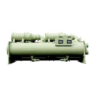
WSC and WMC-B Centrifugal Chillers
Reassembly of Knockdown Shipments
EVAPORATOR
Installation Manual
COMPRESSOR
SUPPORT
STARTER
OIL PUMP
UNIT
CONTROLLER
CONDENSER
IM 1128-2
Group: Chiller
Part Number: 331375601
Effective: July 2015
Supersedes: June 2013
REV: 02
Table of
Contents
Previous
Page
Next
Page
1
2
3
4
5
Advertisement
Table of Contents
Need help?
Do you have a question about the WMC-B 145S and is the answer not in the manual?
Ask a question
Questions and answers
Related Manuals for McQuay WMC-B 145S
Chiller McQuay Seasonpak ALR-035A Installation And Maintenance Data
Packaged air cooled water chiller (48 pages)
Chiller McQuay MVF 030 AR Manual
Vertical fan coil unit (47 pages)
Chiller McQuay WDC Product Manual
Distinction series (84 pages)
Chiller McQuay MCW200D Technical Manual
Ceiling concealed chilled water fan coil unit (19 pages)
Chiller McQuay MAC040A Installation And Maintenance Manual
Air cooled mini chiller (59 pages)
Chiller McQuay WMC Installation, Operation And Maintenance Manual
Magnitude series magnetic bearing centrifugal chillers (68 pages)
Chiller McQuay AGZXXXBS Series Installation, Operation And Maintenance Manual
Air-cooled scroll compressor chiller (106 pages)
Chiller McQuay AGZ 030A Installation And Operation Manual
Air-cooled global chiller (88 pages)
Chiller McQuay ALR 032E Installation Manual
Seasonpak packaged air-cooled water chiller (44 pages)
Chiller McQuay PEH050 Operating And Maintenance Data
Single compressor centrifugal chillers (24 pages)
Chiller McQuay MAC 030 C Installation And Maintenance Manual
Air-cooled mini chiller (52 pages)
Chiller McQuay AGS 120CS/H Installation And Maintenance Manual
Air-cooled screw compressor chiller 60 hertz, r-134a (88 pages)
Chiller McQuay AGR 070A Product Manual
Air-cooled reciprocating chiller, packaged chiller, remote evaporator, 70 to 100 tons, 245 to 350 kw, r-22, r-134a, 60 hertz (60 pages)
Chiller McQuay M5ACV 030 CR Information Manual
Air-cooled chiller (r410a inverter series) (99 pages)
This manual is also suitable for:
Wmc-b 145d
Wmc-b 290d
Wmc-b 400d
Wsc 087
Wsc 100
Wsc 113
...
Show all
Wsc 126
Wsc 063
Wsc 079
Wmc-b 150d
Wmc-b 250d
Table of Contents
Print
Rename the bookmark
Delete bookmark?
Delete from my manuals?
Login
Sign In
OR
Sign in with Facebook
Sign in with Google
Upload manual
Upload from disk
Upload from URL


Need help?
Do you have a question about the WMC-B 145S and is the answer not in the manual?
Questions and answers