Table of Contents
Advertisement
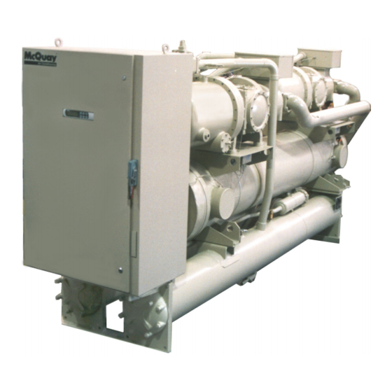
Water-Cooled Screw Compressor Chillers
WGS 130AW to WGS 190AW, Packaged Water-Cooled Chiller
WGS 130AA to WGS 190AA, Chiller with Remote Condenser
120 to 200 Tons, 420 to 700 kW
R-134a, 60 Hz
Software Version WGSD30101H
Operating Manual
OM WGS-5
Group: Chiller
Part Number: 331373701
Effective: November 2008
Supersedes: OM WGS-4
Advertisement
Table of Contents

Related Manuals for McQuay WGS130AA: WGS140AW


Summary of Contents for McQuay WGS130AA: WGS140AW
- Page 1 Operating Manual OM WGS-5 Group: Chiller Part Number: 331373701 Effective: November 2008 Supersedes: OM WGS-4 Water-Cooled Screw Compressor Chillers WGS 130AW to WGS 190AW, Packaged Water-Cooled Chiller WGS 130AA to WGS 190AA, Chiller with Remote Condenser 120 to 200 Tons, 420 to 700 kW R-134a, 60 Hz Software Version WGSD30101H...
-
Page 2: Table Of Contents
2008 McQuay International Illustrations and data cover McQuay International products at the time of publication and we reserve the right to make changes in design and construction at anytime without notice. The following are trademarks or registered trademarks of their respective companies: BACnet from ASHRAE;... -
Page 3: Introduction
Introduction General Description McQuay Model WGS water chillers are designed for indoor installations and are available with factory-mounted water-cooled condensers (Model WGS AW), or arranged for use with remote air-cooled or evaporative condensers (Model WGS AA). Each water-cooled unit (WGS-AW) is completely assembled and factory wired before factory evacuation, charging and testing. -
Page 4: Definitions
Definitions Active Setpoint The active setpoint is the setting in effect at any given moment. This variation occurs on setpoints that can be altered during normal operation. Resetting the chilled water leaving temperature setpoint by one of several methods, such as return water temperature, is an example. - Page 5 Evap Recirc Timer A timing function, with a 30-second default, that holds off any reading of chilled water for the duration of the timing setting. This delay allows the chilled water sensors (especially water temperatures) to take a more accurate reading of the chilled water system conditions. Electronic expansion valve, used to control the flow of refrigerant to the evaporator, controlled by the circuit microprocessor.
- Page 6 (up to 60 minutes). Setpoint Solid state starter as used on McQuay screw compressors. Suction Superheat Suction superheat is calculated for each circuit using the following equation: Suction Superheat = Suction Temperature –...
- Page 7 Stage Up/Down Accumulator The accumulator can be thought of as a bank storing occurrences that indicate the need for an additional fan. Stageup/Stagedown Delta-T Staging is the act of starting or stopping a compressor or fan when another is still operating. Startup and Stop is the act of starting the first compressor or fan and stopping the last compressor or fan.
-
Page 8: Wiring Diagrams
Wiring Diagrams Figure 1, WGS 130AW – 190AW Field Wiring Diagram (Optional Single Point Connection) UNIT MAIN DISCONNECT TERMINAL BLOCK (BY OTHERS) GND LUG 3 PHASE TO COMPRESSOR(S) POWER SUPPLY FUSED CONTROL CIRCUIT TRANSFORMER 120 VAC NOTE: ALL FIELD WIRING TO BE TB1-2 INSTALLED AS NEC CLASS 1 ALARM BELL... - Page 9 Figure 2, WGS 130AA – 190AA Field Wiring Diagram (Remote Air-cooled Condenser) UNIT MAIN DISCONNECT TERMINAL BLOCK (BY OTHERS) GND LUG 3 PHASE TO COMPRESSOR(S) POWER SUPPLY FUSED CONTROL CIRCUIT TRANSFORMER 120 VAC NOTE: ALL FIELD WIRING TO BE TB1-2 INSTALLED AS NEC CLASS 1 ALARM BELL (115 VAC)
-
Page 10: Control Panel Layout
Control Panel Layout Figure 3, Outer (Microprocessor) Panel T2, Unit Controller T13, Circ#1 Controller T14, Circ#1 Load Solenoid T15, Circ#1 EXV Power T23, Circ#2 Controller T24, Circ#2 Load Solenoid T25, Circ#2 EXV Power Unit Controller MHPR11 &12, Mechanical High Pressure Relay Circ#1 Controller Circuit Breaker &... - Page 11 Figure 4, Inner (Power) Panel (Optional Single-Point Power with Disconnect Switches Shown) Circ#1 Solid State Starter Circ#2 Solid State Starter SSS1 Bypass Contactor SSS2 Bypass Contactor Secondary Fuses External Disconnect Handle Circ#1 Circuit Breaker Circ#2 Circuit Breaker Unit Disconnect Switch W/ External Handle T1, Supply Voltage to 120V Transformer...
- Page 12 Figure 5, Circuit Breaker/Fuse Panel Open Location S1 Main Unit On-Off Switch CS2, Circuit#2 On-Off Switch CS1, Circuit#1 On-Off Switch CB11 Circ#1 Circuit Breaker CB12, Circ#1 Sump Heater Open Location CB21, Circ#2 Circuit CB22, Circ#2 Sump Heater Open Locations Location for Optional 115V Receptacle OUTER PANEL INNER PANEL...
-
Page 13: Microtech Ii Controller
MicroTech II Controller Software Version:WGSD30101E Bios: 3.62 BOOT: 3.0F System Architecture The WGS MicroTech distributed control system consists of multiple microprocessor- based controllers that provide monitoring and control functions required for the controlled, efficient operation of the chiller. The system consists of the following components: ... -
Page 14: General Description
General Description The MicroTech II controller’s design permits the chiller to run more efficiently, and it simplifies troubleshooting if a system failure occurs. Every MicroTech II controller is programmed and tested prior to shipment to assist in a trouble-free start-up. The MicroTech II controller can be used to cycle fans on remote air-cooled condensers for head pressure control when the setpoint Water Cooled=N is selected in one of the setpoint menu screens. - Page 15 Unit Enable Selection Enables unit operation from local keypad or digital input. Unit Mode Selection Selects standard cooling, ice, glycol, or test operation mode. Keypad/Display A 4-line by 20-character/line liquid crystal display and 6-key keypad is mounted on each controller. Its layout is shown below. Figure 6, Keypad and Display in MENU Mode Red Alarm Light Menu Key...
-
Page 16: Sequence Of Operation
Sequence of Operation Compressor Heaters With the control power on, 120V power is applied through the control circuit Fuse FU7 to the compressor oil separator heater (HTR-OIL SEP). Startup/Compressor Staging During Cool Mode the following must be true to start a circuit operating. The evaporator and condenser pump (WGS-AW only) outputs must be energized and flow must be established for a period of time defined by the evaporator recirculate setpoint. - Page 17 Low Ambient Start Logic Low pressure operation at start (due to low ambient air temperature)is allowed for every start regardless of the condenser saturated temperature at start or condenser configuration ( water-cooled or remote condenser). This is called Start Logic. START Logic is active for a time period determined by the unit Startup Timer setpoint.
- Page 18 Unit Controller Sequence of Operation Unit power up Unit in Off state The chiller may be disabled via the unit switch, the remote switch, the keypad enable setting, or the BAS network. In addition, the chiller will be disabled if both circuits are disabled, either because of an alarm or the circuit pumpdown switch on each circuit, or if there is a unit alarm.
- Page 19 If the unit is configured as watercooled, the condenser pump will need to be started. Otherwise, the unit can start the first circuit at this point. Is unit watercooled? If load is present, the condenser water pump output will be activated. Condenser pump output on Is flow present? The chiller will then wait for the condenser flow switch to close, during which time...
- Page 20 The second circuit will go through its start sequence at this point. A number of fans may be started with the compressor based on the OAT. Fan Start second circuit. stages will be added/removed as needed to control condenser pressure. The EXV will begin controlling at this point as well.
- Page 21 Circuit Controller Sequence of Operation Unit power up When the circuit is in the Off state the EXV is closed, compressor is off, and all fans are off. The oil heater will be on at this time as long as oil is detected in the separator.
- Page 22 When in the Run state, the compressor will load/unload as needed to satisfy the load. The compressor will also load/unload to load balance with the other compressor if it is running and not in a limited condition. However, it cannot load up until the discharge superheat has been over 22 F for at least 30 seconds.
-
Page 23: Start-Up And Shutdown
2%. Verify that adequate power supply and capacity is available to handle load. 11. Make sure all wiring and fuses are of the proper size. Also make sure that all interlock wiring is completed per McQuay diagrams. 12. Verify that all mechanical and electrical inspections by code authorities have been completed. -
Page 24: Weekend Or Temporary Shutdown
3. Verify that the compressor sump heaters have operated for at least 12 hours prior to start-up. Crankcase should be warm to the touch. 4. Check that the MicroTech II controller is set to the desired chilled water temperature. 5. Start the system auxiliary equipment for the installation by turning on the time clock, ambient thermostat and/or remote on/off switch and water pumps. -
Page 25: Start-Up After Extended Shutdown
Start-up after Extended Shutdown 1. Inspect all equipment to see that it is in satisfactory operating condition. 2. Remove all debris that has collected on the surface of the condenser coils (remote condenser models) or check the cooling tower, if present. 3. - Page 26 Figure 7, Evaporator Pressure Drop WGS 130 – WGS 190 Flow Rate (L/s) 38 44 50 57 63 WGS 130, 140 WGS 160, 170, 190 500 600 700 800 900 1000 2000 Flow Rate (GPM) Minimum Flow Nominal Flow Maximum Flow WGS Model Flow Rate Pressure Drop...
- Page 27 Figure 8, Condenser Pressure Drop WGS 130 – WGS 190 Flow Rate (L/s) 38 44 50 57 63 WGS 170, 190 with Manifold WGS 130, 140, 160 with Manifold WGS 170, 190 without Manifold WGS 130, 140, 160 without Manifold 500 600 700 800 900 1000 2000 Flow Rate (GPM)
-
Page 28: Unit Controller
Unit Controller Unit Inputs/Outputs Table 1, Analog Inputs Description Signal Source Range Condenser EWT or Outdoor Thermister (10k@25°C) -58 to 212°F Ambient Temp. Demand Limit 4-20 mA Current 0 to 100% limit 0 to 10 degrees Chilled Water Reset 4-20 mA Current 60F max. - Page 29 Toggle: Setpoints that have two choices, such as ON and OFF are toggled between the two settings using the Up or Down keys on the controller. NOTE: in some software versions the terms “inhibit” and “hold” are used interchangeably. Table 5, Unit Controller Setpoints Description Default Range...
- Page 30 Description Default Range Type Stage Up Delay 5 min 0 to 60 min Disc. Temp Sensor Type PT1000 NTC, PT1000 Alarms Low Evap Pressure-Unload 28 psi [0,26] to 45 psi Low Evap Pressure-Hold 30 psi [0,28] to 45 psi Low Oil Level Delay 120 sec 10-180 sec High Oil Press Diff Delay...
-
Page 31: Circuit Controller
Table 8, Low Evaporator Pressure Inhibit Mode Range Unit Mode = Cool 30 to 45 Psig Unit Mode = Cool w/Glycol, Ice w/ Glycol 15 to 45 Psig Table 9, Low Evaporator Pressure Unload Mode Range Unit Mode = Cool 28 to 45 Psig Unit Mode = Cool w/Glycol, Ice w/ Glycol 15 to 45 Psig... -
Page 32: Circuit Setpoint Table
Table 13, Digital Outputs Description Output OFF Output ON Fan 1 Contactor (air cooled only) Fan off Fan on Fan 2 Contactor (air cooled only) Fan off Fan on Fan 3 Contactor (air cooled only) Fan off Fan on Fan 4 Contactor (air cooled only) Fan off Fan on Fan 5 Contactor (air cooled only) - Page 33 Description Default Range EXV control Auto Auto, manual Manual EXV position 0-6386 Service Pumpdown No,Yes Preopen Timer (water cooled only) 20 to 120 seconds Sensors (NOTE 1) Evap pressure offset -10.0 to 10.0 psi Cond pressure offset -10.0 to 10.0 psi Suction temp offset -5.0 to 5.0 deg Discharge temp offset...
-
Page 34: Alarms And Events
Alarms and Events Situations may arise that require some action from the chiller or that should be logged for future reference. A condition that causes a shutdown and requires manual reset is known as a stop alarm. Other conditions can trigger what is known as an event, which may or may not require an action in response. - Page 35 The alarm will reset automatically when the condenser state is Run again. This means the alarm stays active while the unit waits for flow, then it goes through the recirculation process after flow is detected. Once the recirculation is complete, the condenser goes to the Run state which will clear the alarm.
-
Page 36: Unit Events
Unit Events The following unit events are logged in the event log with a time stamp. Entering Evaporator Water Temperature Sensor Fault Event description (as shown on screen): Evap EWT Sens Fault Trigger: Sensor shorted or open Action Taken: Return water reset cannot be used. Reset: Auto reset when sensor is back in range. - Page 37 High Lift Pressure Alarm description (as shown on screen): Lift Pressure High N Trigger: Condenser Saturated Temperature > Max Saturated Condenser Value for time > High Lift Delay set point Action Taken: Rapid stop circuit Reset: This alarm can be cleared manually via the Unit Controller keypad. Mechanical High Pressure Alarm description (as shown on screen): Mech High Pressure N Trigger: Mechanical High Pressure switch input is low...
-
Page 38: Circuit Events
No Pressure Change At Start Alarm description (as shown on screen): NoPressChgAtStart N Trigger: After start of compressor, at least a 1 psi drop in evaporator pressure or 5 psi rise in discharge pressure has not occurred after 15 seconds. Action Taken: Rapid stop circuit Reset: This alarm can be cleared manually via the Unit Controller keypad. -
Page 39: Alarm Logging
Reset: While still running, the event will be reset if saturated condenser temperature < (High Saturated Condenser - Unload Value – 10 F). The event is also reset if the unit mode is switched to Ice, or the compressor state is no longer Run. Oil Level Low Event description (as shown on screen): Oil Level Low Cir N Trigger: Oil Level Switch input is open for time greater than Low Oil Level Delay while... -
Page 40: Event Logging
A separate alarm log stores the last 25 alarms to occur. When an alarm occurs, it is put into the first slot in the alarm log and all others are moved down one, dropping the last alarm. In the alarm log, the date and time the alarm occurred are stored, as well as a list of other parameters. -
Page 41: Unit Enable
Unit Enable Enabling and disabling the chiller is controlled by the Unit Enable Setpoint with options of OFF and ON. Enabling allows the unit to start if there is a call for cooling and also starts the evaporator pump. This setpoint (in other words, enabling the unit to run) can be altered by the: ... -
Page 42: Unit Mode Selection
a. Switches source is used when there is no BAS interface used. This allows the unit switches to function as pumpdown and shut down switches for the circuit. This option is also used with applications using the remote start/stop input and not using a BAS interface. -
Page 43: Unit States
The Remote ICE Mode Switch (usually a time clock) is a field installed option and is used to switch from ice mode operation at night to cooling mode operation during the day. This requires that the Control Source be set to SWITCHES, which in this case refers to the Remote ICE Mode Switch. -
Page 44: Evaporator Pump Control
T3 – Transition from Pumpdown to Off Requires any of the following All circuits have finished pumpdown and are off A unit alarm is active Unit switch is “off” T4 – Transition from Auto to Off Requires any of the following ... -
Page 45: Leaving Water Temperature (Lwt) Reset
T3 – Transition from Run to Off Requires any of the following Unit state = Off AND LWT > Freeze setpoint Low OAT Lockout is active AND No compressors running AND LWT > 70°F T4 – Transition from Start to Off Requires any of the following ... - Page 46 Return Reset LWT set Point+Max Reset (54) Active Max Reset (10) LWT Set Point (44) Start Reset Delta T Evap Delta T ( The active setpoint is reset using the following parameters: 1. Cool LWT setpoint 2. Max Reset setpoint 3.
-
Page 47: Planned Unit Capacity Overrides
4-20 mA Reset - Cool Mode (54) Active Max Reset (10) Cool LWT Set Point (44) Reset Signal (mA) Reset Type – OAT This reset can only be used if the unit is configured as air-cooled. The Active Leaving Water variable is reset based on the outdoor ambient temperature. Parameters used: 1. -
Page 48: Condenser Pump And Tower Control
Soft Load – (ON/OFF) Begin Capacity Limit – (Unit %) Soft Load Ramp – (seconds) The Soft Load Unit Limit increases linearly from the Begin Capacity Limit setpoint to 100% over the amount of time specified by the Soft Load Ramp setpoint. If the option is turned off, the soft load limit is set to 100%. -
Page 49: Cooling Tower Control
Transitions: T1 – Transition from Off to Start Requires any of the following Unit state = Auto AND any circuit available AND LWT error > Startup Delta Cond Water Freeze Alarm T2 – Transition from Start to Run ... - Page 50 Additional stages can turn on (up to the number specified by the Tower Stages setpoint) when above conditions are met for the next stage. Down staging shall occur when the following conditions are met: The stage down timer completes ...
-
Page 51: Evaporative Condenser Control
It is acceptable to use WGS-A chillers (less condenser) with evaporative condensers. It is the installer's responsibility to provide the evaporative condenser control because this condenser type is not available from McQuay. The WGS-A software does not directly support evaporative-cooled applications since there is a variety of fan configurations and pumps available from the manufacturers of evaporative condensers. - Page 52 Use water treatment with evaporative condensers. Failure to prevent microbiology growth, scaling and corrosion can damage the unit. 10. Damage caused or contributed by improper water treatment may not be covered by McQuay’s warranty. WGS 130A to 190A OM WGS-5...
- Page 53 , BACnet or Modbus. Refer to the other McQuay brochures listed in ORKS this manual for a complete description of capabilities. As a general statement, the McQuay communication cards do NOT support the evaporative condenser. The desired interface points for the condenser must be provided by others and through the control system provided with the evaporative condenser.
-
Page 54: Circuit Controller Functions
Circuit Controller Functions Refrigerant Calculations Refrigerant Saturated Temperature Refrigerant saturated temperature is calculated from the pressure sensor readings for each circuit. The pressure will be fitted to a curve made up of 12 straight line segments. The points used to define these segments are shown in the following tables. Table 18, Evaporator Pressure Conversion: Pressure (PSI) Temperature (... -
Page 55: Compressor Control
Circuit Switch = OFF Technician password active Circuit Mode setpoint = TEST A test menu can then be selected to allow activation of the outputs. It is possible to switch each digital output ON or OFF and set the analog outputs to any value. Upon entering test mode, all outputs will always default to the off state. - Page 56 Starting A compressor will start (stage up): IF LWT is above the Active LWT Setpoint plus the Startup Delta-T SP AND no compressors are running OR all running compressors are at full load Stopping A compressor will stop (stage down); IF LWT is below the Active LWT Setpoint minus the Stop Delta-T SP AND other compressors are running or not;...
- Page 57 Every 12 seconds, the current LWT is subtracted from the value 12 seconds back. This value is added to a buffer containing values calculated at the last five intervals. The final result is a slope value that is an average over the past 60 seconds. Count In Load Balance Flag A circuit will be counted for load balancing only if all of the following are true: ...
-
Page 58: Internal Capacity Overrides
Internal Capacity Overrides The following conditions override the automatic slide control when the chiller is in COOL mode or ICE mode. These overrides keep the circuit from entering a condition in which it is not designed to run. Any compressor running with capacity limits because of these conditions is considered to be at full load in the compressor staging logic. -
Page 59: Slide Positioning
Unit Capacity Overrides Unit capacity limits override the automatic slide control when the chiller is in COOL mode only. The active capacity limit as well as the estimated unit capacity will be calculated in the unit controller and sent to all circuits. If the unit capacity is greater than the active capacity limit, then no circuit will increase slide position. - Page 60 Figure 9, Slide Indicator and Coils Load Coil Unload Coil Slide Indicator Calibration Procedure: 1. The circuit to be calibrated should be near normal operating temperatures. Note that the compressor requires sufficient oil pressure to unload the compressor while it is running, and may load up due to lack of oil feed pressure.
-
Page 61: Expansion Valve Control
Manual Slide Control Mode The slide position on each circuit can be controlled manually. A setting on the compressor setpoints screen in each circuit controller allows the operator to select manual slide control. On the same screen, a slide target can be selected, from 0% to 100%. Anytime a circuit is in manual slide control, it is considered to be at full load in the staging logic. - Page 62 Superheat Control In superheat control, suction superheat is controlled directly by the EXV. The superheat target varies linearly from 6 to 10 degrees F as discharge superheat changes from 30 degrees F to 22 degrees F. PID logic controls the superheat to the target value. When the EXV transitions to the superheat control state, the target will start at the current suction superheat value.
- Page 63 EXV State has been Preopen for a time greater than the preopen timer set point T3 – Transition from Pressure Control to Superheat Control Requires all of the following Suction Superheat > Superheat target Evap LWT <= 60 F ...
- Page 64 EXV State = Pressure AND Discharge Superheat >= 22 degrees F for at least 3 minutes Discharge Temperature <= 180F T3 – Transition from Superheat Control to Pressure Control Requires any of the following Evap LWT > 63F ...
-
Page 65: Oil Heater Control
Oil Heater Control The oil heater shall be on when the compressor is not running AND the oil level input is closed for 15 seconds. This output will turn off immediately when either the oil level switch opens or the compressor state is no longer off. Starter Communications The Modbus protocol is used to establish communications between the compressor starter and the circuit controller on the supervisor port, with the circuit controller acting as the... -
Page 66: Condenser Fan Control
The most recent fault code shall be stored in the alarm log parameter list. The fault reset signal is sent to the starter when the operator clears the active alarm on the unit controller. The starter fault codes and their corresponding alarms are shown in the table below: Table 21, Starter Fault Codes Fault Code Starter Fault Description... - Page 67 Remote evaporative condensers require their own self-contained, on-board, head pressure controls. See page 51. Fan Stages There are up to 6 stages of Fantrol available. See the table below: Table 22, Fantrol Staging Fantrol Stage Fans On 1,2,3 1,2,3,4 1,2,4,5,6 1,2,3,4,5,6 Staging Up The controller looks at high the discharge pressure is and how quickly it is rising by...
-
Page 68: Condenser Fan Vfd
The Stage Down Error Step is added to Stage Down Accumulator once every Stage Down Error Delay seconds. When the Stage Down Error Accumulator is greater than the Stage Down Error Setpoint, another stage of condenser fans turned off. When a stage down occurs or the saturated temperature rises back within the Stage Down deadband, the Stage Down Error Accumulator is reset to zero. -
Page 69: Using The Controller
Using the Controller 4x20 Display & Keypad Layout The 4-line by 20-character/line, liquid crystal display and 6-key keypad for both of the circuit controller and the unit controller is shown below. Figure 10, Display (in MENU mode) and Keypad Layout MENU Key Left Arrow Key and Red Alarm Light... - Page 70 setpoint values. The SCROLL mode allows the user to move about the matrix (from one menu to another, one at a time) by using the four ARROW keys. When in the MENU mode (as shown in Figure 10), pressing the LEFT ARROW key will select the ALARM menus, the RIGHT ARROW key will select the VIEW menus and the UP key the SET menus.
-
Page 71: Security
4. Press the DOWN key to scroll down through the setpoint menus to the third menu which contains Evap LWT=XX.XF. 5. Press the ENTER key to move the cursor down from the top line to the second line in order to make the change. 6. -
Page 72: Menu Descriptions
Menu Descriptions Unit Controller Various menus are shown in the controller display. Each menu screen shows specific information. In some cases menus are used only to view the status of the unit, in some cases they are used for checking and clearing alarms, and in some case they are used to set the setpoint values that can be changed. - Page 73 Unit Controller Menu Matrix When scrolling through the screens, the following matrix is used: “VIEW” SCREENS VIEW VIEW VIEW VIEW VIEW VIEW VIEW VIEW EVENT UNIT UNIT REFRG REFRG CIR 1 CIR 2 FANS TOWER STATUS TEMP CIR 1 CIR 2 VIEW VIEW VIEW...
- Page 74 ALARM menu: ALARM < ACTIVE < < < VIEW menu: Water-cooled Air-cooled VIEW < UNIT VIEW < UNIT < CIR STATUS < CIR STATUS <REFRIGERANT <REFRIGERANT < TOWER < FANS VIEW UNIT menu: VIEW < STATUS UNIT < TEMP < <...
- Page 75 Unit Status will display one of the following: Auto Off:Ice Mode Timer Off:All Cir Disabled Off:Unit Alarm Off:Keypad Disable Off:Remote Switch Off:BAS Disable Off:Unit Switch Off:Test Mode Auto:Wait for load Auto:Cond Recirc Auto:Evap Recirc Auto:Wait Cond Flow Auto:Wait Evap Flow Auto:Pumpdown Pump states include Off, Start, and Run.
- Page 76 View Circuit Status In the following VIEW CIR screens, the N field indicates which circuit (#1, #2) is being viewed. Certain screens located in the circuit controller are also displayed here on the unit controller for convenience. VIEW CIR N STATUS(1) {Circuit Status} Slide Pos= 000.0%...
- Page 77 VIEW REFRG CIR N (2) Sat Evap= XXX.XF Sat Cond= XXX.XF VIEW REFRG CIR N (3) Suct Temp = XXX.X F Disc Temp = XXX.X F VIEW REFRG CIR N (4) XXX.X F Suct SH= XXX.X F Disc SH= VIEW REFRG CIR N (5) Evap Approach=XX.XF Cond Approach=XX.XF EXV position = XXXX...
- Page 78 Screen Definitions – ALARM ALARM LOG: XX {Alarm Description} hh:mm mm/dd/yy {Parameters} The most recent 25 alarms, either shutdown or limit, are shown in this menu and subsequent menus located under it. The last alarm is shown first. ARROW DOWN from this menu will go to the next-to-last alarm, ARROW DOWN again will go to the second from last, and so on through the last 25 occurrences.
- Page 79 Screen Definitions – SET Unit Set Points SET UNIT SPs Enable=On Mode= COOL Source = KEYPAD Unit Enable settings can be OFF and ON as determined from the Unit Enable setpoint. Unit Enable is an external signal or a keypad setting that keeps the unit off when the setting is OFF and allows it to run if there is a call for cooling when the setting is ON.
- Page 80 SET UNIT SPs Max Pulldn=X.XF/min EvapRecTimer=XXX sec Evap Pump= #1 Only Water-cooled: Air-cooled: SET UNIT SPs (6) SET UNIT SPs Watercooled= Yes Watercooled= No CondRecTimer=XXX sec Cond Pump= #1 Only SET UNIT SPs Reset Type= none Max Reset = XX.XF StrtResetDT= XX.XF SET UNIT SPs Soft Load= Off...
- Page 81 Water-cooled: Air-cooled: SET UNIT SPs (12) SET UNIT SPs (12) Sensor Offset Sensor Offset Cond EWT= XX.XF OAT= XX.XF Cond LWT= XX.XF SET UNIT SPs (13) CLOCK mm/dd/yyyy hh:mm SET UNIT SPs (14) Units = F/psi Lang = ENGLISH After entering a valid manager password, selecting F/psi will provide IP units; selecting C/kPa will provide SI units.
- Page 82 SET COMP SPs Pumpdown Pressure= XX.X psi Time Limit= XXX sec SET COMP SPs Light Load Stage Down Point=XX% slide Stg Up Delay= XX min SET COMP SPs Discharge Temp Sensor Type=PT1000 Alarm Set Points SET ALARM LIMITS (1) Low Evap Pressure Hold=XX.Xpsi Unload=XX.Xpsi The LowEvPrHold (Low Evaporator Pressure Hold) and LowEvPrUnld (Low Evaporator...
- Page 83 Evap/Cond FlowProof is the flow switch interlock. Closing the flow switch, and therefore proving the existence of chilled water flow, resets this trip. It is recommended that these settings not be changed. SET ALARM LIMITS (5) Cond Freeze= XX.XF Cond Flow Proof=XXXs Set Alarm Limits (5) is accessible only if unit is configured as water-cooled.
- Page 84 SET TOWER SPs Tower Control=None Tower Stages= 2 When Tower Control is None, the control of condenser water temperature is not by the MicroTech II controller and assumed to be furnished elsewhere. Tower Stages is the number of tower fans to be staged by the controller, choices are 0, 1, or 2.
- Page 85 Increment = [(Error) * (Error Gain setpoint)] + [(Slope) * (Slope Gain setpoint)] Where: Error = ECWT – Valve Setpoint Slope = (Present CP) – (Previous CP) When the Error is > the Valve Deadband setpoint, the valve position analog output (% of full scale) is updated according to the following equation.
- Page 86 Operation After Start When the condenser pump is in the RUN state, the valve output shall be controlled in one of two modes as specified by the Valve/VFD Control setpoint. The controlled parameter shall be the condenser entering water temperature. When the desired output signal varies from 0 to 100%, the output voltage shall vary as shown below.
-
Page 87: Circuit Controller
Tower Fan 1= Off Tower Fan 2= Off TEST UNIT Tower Bypass= XXX.X Tower VFD Spd= XXX.X Circuit Controller The display on the circuit controller displays information about the circuit that it is controlling. Setpoint availability will be limited to setpoints that are unique to that circuit. Other set points are changed at the Unit Controller. - Page 88 VIEW < UNIT < CIR STATUS <REFRIGERANT < FANS Fan data is available only when unit is configured as air-cooled. Set menu: <COMPRESSOR SPs < EXV SPs < FAN SPs <SENSOR OFFSETS Fan setpoints are available only when unit is configured as air-cooled. Screen Definitions –...
- Page 89 VIEW CIR STATUS Hours = XXXXX Starts = XXXXX KW Hours= XXXXXXX A KW hours counter has been added to the Circuit control Circuit Status Screen. The KW Hours field will display up to 9,999,999 kW-Hours. VIEW CIR STATUS Current (amps) VIEW CIR STATUS Voltage L1-2 L2-3 L3-1...
- Page 90 Sat Evap = XXX.X F Sat Cond = XXX.X F VIEW REFRIGERANT (3) Suct Temp = XXX.X F Disc Temp = XXX.X F VIEW REFRIGERANT (4) XXX.X F Suct SH= XXX.X F Disc SH= VIEW REFRIGERANT (5) Evap Approach=XX.XF Cond Approach=XX.XF VIEW REFRIGERANT (6) MaxCondSatT= XXX.XF EXV Ctrl=Superheat...
- Page 91 Clear Cycle Tmr= no Comp Size= XXX Max Slide= XXX.X % SET COMP SPs Circuit Mode=Enable Slide Target= XXX.X% Slide Control=auto SET STARTER SPs Motor FLA= XXX amps Motor RLA= XXX amps The starter set points are stored in permanent memory on the starter and the Circuit control set points will be reset to the values stored on starter when the Circuit control is powered up.
- Page 92 Slide Pos= XXX.X% Fan Set Points SET FAN SPs Number of fans = X Fan VFD = Enable SET FAN SPs Stg On Deadband(F) Stg1=XX.X Stg2=XX.X Stg3=XX.X Stg4=XX.X SET FAN SPs Stg Off Deadband(F) Stg2=XX.X Stg3=XX.X Stg4=XX.X Stg5=XX.X SET FAN SPs VFD Min Speed= VFD Min Speed= XXX% SET FAN SPs...
-
Page 93: Editing Review
TEST CIRCUIT EXV Position=XXXX TEST CIRCUIT Condenser Fans: 1=Off 2=Off 3=Off 4=Off 5=Off 6=Off Editing Review Editing is be accomplished by pressing the ENTER key until the desired field is selected. This field shall be indicated by a blinking cursor under it. The arrow keys shall then operate as defined below. -
Page 94: Bas Interface
If an interface module was ordered, one of the following BAS interface installation manuals was shipped with the unit. Contact your local McQuay sales office for a replacement, if necessary or download from www.mcquay.com. -
Page 95: Unit Troubleshooting Chart
Unit Troubleshooting Chart WARNING Troubleshooting can cause severe personal injury or death. Troubleshooting must be performed by trained, experienced technicians only. PROBLEM POSSIBLE CAUSES POSSIBLE CORRECTIVE STEPS Main switch, circuit breakers open. Close switch Fuse blown. Check electrical circuits and motor winding for shorts or grounds. - Page 96 PROBLEM POSSIBLE CAUSES POSSIBLE CORRECTIVE STEPS Lack of refrigerant. Check for leaks. Repair and add charge. Evaporator dirty. Clean chemically. Clogged liquid line filter-drier. Replace cartridge(s). Expansion valve malfunctioning. Check and reset for proper superheat. Low Suction Replace if necessary. Pressure Condensing temperature too low.
- Page 98 All McQuay equipment is sold pursuant to McQuay’s Standard Terms and Conditions of Sale and Limited Product Warranty. Consult your local McQuay Representative for warranty details. Refer to form 933-430285Y-00-A (09/08). To find your local representative, go to www.mcquay.com This document contains the most current product information as of this printing. For the most up-to-date product information on this unit and others, please go to www.mcquay.com.
Need help?
Do you have a question about the WGS130AA: WGS140AW and is the answer not in the manual?
Questions and answers