Table of Contents

Related Manuals for McQuay WMC


Summary of Contents for McQuay WMC
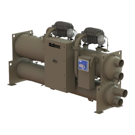
- Page 1 Installation, Operation, IOM 1210-1 and Maintenance Manual Group: Chiller Part Number: IOM1210-1 Date: August 2014 Magnitude ® Magnetic Bearing Centrifugal Chillers Model WMC, C Vintage 125 to 400 Tons (440 to 1400 kW) HFC-134a Refrigerant 50/60 Hz...
-
Page 2: Table Of Contents
©2014 Daikin Applied. Illustrations and data cover the Daikin Applied product at the time of publication and we reserve the right to make changes in design and construction at any time without notice. IOM 1210-1 • MAGNITUDE MODEL WMC CHILLERS www.DaikinApplied.com ®... - Page 3 Document Attached: Final Order Acknowledgement Notes: The most common problems delaying start-up and affecting unit reliability are: Field installed compressor motor power supply leads too small. Questions: Contact the local McQuay International sales representative. State size, number and type of conductors and conduits installed:...
-
Page 5: Introduction
This manual provides installation, operation, and maintenance information for McQuay WMC Magnitude centrifugal chillers with ® the MicroTech II controller. ® WARNING Electric shock hazard. Improper handling of this equipment can cause personal injury or equipment damage. This equipment must be properly grounded. -
Page 6: General Description
® are equipped with a single evaporator and a single condenser All McQuay International centrifugal chillers must be along with either one or two compressors depending on the commissioned by a factory-trained McQuay International model. service technician. Failure to follow this startup procedure can... -
Page 7: The Control System
LCD can display most of the same information as the OITS and can be used to operate the chiller independently of the OITS. “The Controller” section on page 48 for information. www.DaikinApplied.com IOM 1210-1 • MAGNITUDE MODEL WMC CHILLERS ®... -
Page 8: Installation
(Models WMC150D, 275D, 290D, 400D) Minimum 3’ Clearance Minimum 4’ Clearance in front of control boxes and electrical panels NOTE: Hinged type waterboxes may require more clearance. Consult a McQuay International sales representative for details. IOM 1210-1 • MAGNITUDE MODEL WMC CHILLERS www.DaikinApplied.com... -
Page 9: Unit Dimensions And Shipping Weight
E3012 / C2612 168.5 (4280) 55.2 (1402) 94.3 (2395) 11574 (5250) Width is based on unit without optional harmonic filters. ** Shipping weight is based on unit with standard tube configuration. www.DaikinApplied.com IOM 1210-1 • MAGNITUDE MODEL WMC CHILLERS ®... -
Page 10: Mounting
The water heads can be interchanged (end for end) so that the water connections can be made at either end of the unit. If this is done, use new head gaskets and relocate the control sensors. IOM 1210-1 • MAGNITUDE MODEL WMC CHILLERS www.DaikinApplied.com ®... -
Page 11: Condenser Water Temperature Control
Speed adjustments may be required during the initial temperatures are either too high or too low. The WMC chiller chiller startup as determined by the service technician. provides several options to assist the chiller plant designer in NOTE: Not using the MicroTech ®... -
Page 12: Relief Valves
“Front Seated Position” and all refrigerant will flow through the back outlet port, as shown in Figure 9. When the stem of IOM 1210-1 • MAGNITUDE MODEL WMC CHILLERS www.DaikinApplied.com ®... -
Page 13: Field Insulation
E2612 122 (11.3) CAUTION 290D E2612 122 (11.3) Do not use power factor correction capacitors with WMC 400D E3012 141 (13.1) chillers. Doing so can cause harmful electrical resonance in the system. Correction capacitors are not necessary since VFDs inherently maintain high power factors. - Page 14 Figure 12: Wiring Index IOM 1210-1 • MAGNITUDE MODEL WMC CHILLERS www.DaikinApplied.com ®...
- Page 15 IOM 1210-1 • MAGNITUDE MODEL WMC CHILLERS ®...
- Page 16 Figure 13: Controller Box Wiring IOM 1210-1 • MAGNITUDE MODEL WMC CHILLERS www.DaikinApplied.com ®...
- Page 17 IOM 1210-1 • MAGNITUDE MODEL WMC CHILLERS ®...
- Page 18 Figure 14: Power Box Single and Multi Point Wiring IOM 1210-1 • MAGNITUDE MODEL WMC CHILLERS www.DaikinApplied.com ®...
- Page 19 IOM 1210-1 • MAGNITUDE MODEL WMC CHILLERS ®...
-
Page 20: Communication Setup For Multiple Chillers
If trying to If the temperature of where the chiller is located is expected to connect WMC A vintage chillers to eachother or to B exceed 104°C (40°C), then the refrigerant must be removed. or C vintage chillers, consult a McQuay International For additional tasks required, contact McQuay International service representative. -
Page 21: Pre-Start Checklist
Document Attached: Final Order Acknowledgement Notes: The most common problems delaying start-up and affecting unit reliability are: Field installed compressor motor power supply leads too small. Questions: Contact the local McQuay International sales representative. State size, number and type of conductors and conduits installed:... -
Page 22: Operation
During speed until the minimum speed limit has been reached. the initial startup of the chiller, the McQuay International If further unloading is required, the IGV assemblies will technician will be available to answer any questions and close as required to satisfy the load. -
Page 23: Operator Interface Touch Screen (Oits)
This method of disabling will cause the chiller to act in a similar manner as when it is disabled using the Unit Switch in the “Switches” or “BAS” mode. www.DaikinApplied.com IOM 1210-1 • MAGNITUDE MODEL WMC CHILLERS ®... - Page 24 • COMPRESSOR STATUS, shown for both compressor #1 and #2, is MODE followed by STATE followed by the SOURCE that is the device or signal that created the STATE. The possible combinations are shown in Table IOM 1210-1 • MAGNITUDE MODEL WMC CHILLERS www.DaikinApplied.com ®...
- Page 25 Figure 18: Compressor State Information • SET button: Toggles between the Setpoint Screens (descriptions start on page 26) that are used for changing setpoints and the Service Screen (Figure 47 on page 40). www.DaikinApplied.com IOM 1210-1 • MAGNITUDE MODEL WMC CHILLERS ®...
- Page 26 23. Note that operation of the condenser and evaporator water pumps and operation of the tower constitute most of the data flow. An illuminated block indicates that either an input or output signal exists. IOM 1210-1 • MAGNITUDE MODEL WMC CHILLERS www.DaikinApplied.com ®...
- Page 27 Detail View Screen. Reference the Information figures in the "Detail View Screen" section starting on page 23 more details. www.DaikinApplied.com IOM 1210-1 • MAGNITUDE MODEL WMC CHILLERS ®...
- Page 28 When in any Setpoint setpoints.) Appropriate setpoints are factory set and checked Screen, pressing the SET button again will toggle to the by a McQuay International service representative during Service Screen, shown in Figure 47 on page 40.
- Page 29 (the background will turn blue). The Numeric Keypad and Action buttons in the lower left-hand corner of the screen will become active (the background will turn green). www.DaikinApplied.com IOM 1210-1 • MAGNITUDE MODEL WMC CHILLERS ®...
- Page 30 • O = Operator Level (the password number for operator level is 100) • M = Manager Level (the password number for manager level is 2001) • T = Technician Level (the password number for technician level is only provided to McQuay International technicians) IOM 1210-1 • MAGNITUDE MODEL WMC CHILLERS www.DaikinApplied.com...
- Page 31 20 to 45 psi Min evap pressure – inhibit loading NOTE: The setpoints listed in Table 6 should only be changed by a McQuay International technician. Contact a McQuay International service representative for more information. www.DaikinApplied.com IOM 1210-1 • MAGNITUDE MODEL WMC CHILLERS ®...
- Page 32 Setpoints 1 and 2 in Table 8 on page 31. The setpoints listed in Table 7 should only be changed by a McQuay International technician. Contact a McQuay International service representative for more information. IOM 1210-1 • MAGNITUDE MODEL WMC CHILLERS www.DaikinApplied.com ®...
- Page 33 Valve Setpoint/VFD Stage: Both valve and VFD None: No tower fan control Temperature: Fan and valve controlled by EWT Cooling Tower Control None None, Temperature, Lift Lift: Fan and valve controlled by lift pressure www.DaikinApplied.com IOM 1210-1 • MAGNITUDE MODEL WMC CHILLERS ®...
- Page 34 (I), plus a tower bypass valve is controlled to provide a minimum condenser EWT. There is no interconnection between the fan control and the valve control. See Figure 34 Figure IOM 1210-1 • MAGNITUDE MODEL WMC CHILLERS www.DaikinApplied.com ®...
- Page 35 Figure shows that the default temperature at which the valve opens completely is 65°F. This temperature is the Valve SP and is adjustable. Temperature (°F) 4 Fan Stages 1 Fan Stage www.DaikinApplied.com IOM 1210-1 • MAGNITUDE MODEL WMC CHILLERS ®...
- Page 36 II would recommend for ® B. VALVE Setpoint Screen proper head control on the WMC unit. The third Analog Output 1. SP1. Select NC or NO depending if valve is normally (Tower Reset) is only configurable from the MicroTech ®...
- Page 37 To avoid possible equipment damage, these setpoints should be set by personnel experienced with setting up this type of control. www.DaikinApplied.com IOM 1210-1 • MAGNITUDE MODEL WMC CHILLERS ®...
- Page 38 Demand Limit Enable OFF, ON signal OFF – signal is ignored NOTE: Setpoints that have a technician level password (T) should only be changed by a McQuay International technician. Contact a McQuay International service representative for more information. CAUTION * Chiller Nameplate RLA MUST match chiller dataplate per compressor.
- Page 39 The maximum rate at which the leaving water temperature can drop (chiller mode = COOL) is limited at all times by the Maximum Rate setpoint. If the rate exceeds this setpoint, capacity increases are inhibited. www.DaikinApplied.com IOM 1210-1 • MAGNITUDE MODEL WMC CHILLERS ®...
- Page 40 LWT NOTES: 1. If both compressors have the same sequence number, they will automatically balance starts and run-hours. 2. Setpoints 11 through 14 display compressor staging strategy. IOM 1210-1 • MAGNITUDE MODEL WMC CHILLERS www.DaikinApplied.com ®...
- Page 41 Shutdown Delta T 3.0°F 0.0 to 3.0 °F Degrees below setpoint for chiller to stop Leaving Water Temp - Cool 44.0°F 40.0 to 80.0 °F Evaporator LWT setpoint in COOL mode www.DaikinApplied.com IOM 1210-1 • MAGNITUDE MODEL WMC CHILLERS ®...
- Page 42 The pLAN Comm button and the LOAD UCM button (lower left of the screen) are used for setting up multiple chillers at startup Figure 46: LWT Reset (Cool Mode) by a McQuay International startup technician. Pressing the Date/Time button on the right side of the Service (54.0°F)
- Page 43 OITS PC was off. Trend history is not affected if only the OITS screen (not the OITS PC) is off or in sleep mode. For details on how to download the trend history, reference the "Alarm History Screen" section starting on page www.DaikinApplied.com IOM 1210-1 • MAGNITUDE MODEL WMC CHILLERS ®...
- Page 44 USB is complete. • Repeat this process for each desired day of trend history. Each day must be downloaded individually. It is not possible to download multiple days of trend history at once. IOM 1210-1 • MAGNITUDE MODEL WMC CHILLERS www.DaikinApplied.com ®...
- Page 45 Active Alarms Screen. (In this manual, the red ALARM button is displayed as an example Figure 16 on page 22.) Figure 52: Active Alarms Screen www.DaikinApplied.com IOM 1210-1 • MAGNITUDE MODEL WMC CHILLERS ®...
- Page 46 Auto-clears Check Valve Fault 1 CHILLER STOP - Check Valve Failure Locked off (requires local reset) Check Valve Fault 2 CHILLER STOP - Check Valve Failure Locked off (requires local reset) IOM 1210-1 • MAGNITUDE MODEL WMC CHILLERS www.DaikinApplied.com ®...
- Page 47 Locked off if Tripped 3x in 50 min COMPR STOP - Compressor Fault Starter Fault Compressor 1 Reset is dependent on specific alarm (previously used for WMC general compressor fault) COMPR STOP - Compressor Fault Starter Fault Compressor 2 Reset is dependent on specific alarm...
- Page 48 Table 16: Compressor Warning Alarms Description OITS Alarm Message Alarm Reset Repower After Power Loss 1 COMPR STOP - Line Voltage Low Auto-clears Repower After Power Loss 2 COMPR STOP - Line Voltage Low Auto-clears IOM 1210-1 • MAGNITUDE MODEL WMC CHILLERS www.DaikinApplied.com ®...
- Page 49 COMPR STOP - Compressor Fault Auto-clears Drive Fault 2 COMPR STOP - Compressor Fault Auto-clears Internal Control Fault 1 COMPR STOP - Compressor Fault Auto-clears Internal Control Fault 2 COMPR STOP - Compressor Fault Auto-clears www.DaikinApplied.com IOM 1210-1 • MAGNITUDE MODEL WMC CHILLERS ®...
-
Page 50: The Controller
SET as shown in Figure 53. COMMISSION Figure 53: Controller Keypad is normally displayed under SET and is used by McQuay International technicians at chiller startup. Red Alarm Light Behind For more information on commissioning, contact a MENU Key McQuay International service representative. - Page 51 COMPRESSOR” section of the Menu Matrix (see Table 19 on page 50). The left screen is the data for Compressor 1 while the right screen is the data for Compressor 2. www.DaikinApplied.com IOM 1210-1 • MAGNITUDE MODEL WMC CHILLERS ®...
- Page 52 Comp Alarm = nnnnn Comp Alarm = nnnnn Un-Balance Fr=+nnnn Un-Balance Fr=+nnnn Ax=+nnnn Rr=+nnnn Ax=+nnnn Rr=+nnnn VIEWCOMP(18) BMCC VIEWCOMP#2(18) BMCC BMC3.0.xxxx 01Sep13 BMC3.0.xxxx 01Sep13 CC 3.0.xxxx `HH:MM:SS CC 3.0.xxxx `HH:MM:SS Sr#nnnnn-nnnnn-nnnnn Sr#nnnnn-nnnnn-nnnnn IOM 1210-1 • MAGNITUDE MODEL WMC CHILLERS www.DaikinApplied.com ®...
- Page 53 Lang = English SET UNIT SPs (14) Protocol = MODBUS Id #= 001 Units =IP Baud Rate = 19200 SET UNIT SPs (15)Exv EXV Gain=078 Md078 Offset=0700 Md0700 Prs Ctrl DOut10.0°F www.DaikinApplied.com IOM 1210-1 • MAGNITUDE MODEL WMC CHILLERS ®...
- Page 54 “Exit” will cause that prior screen to be levels of access to changeable parameters (the technician displayed. If the SET PASSWORD screen was initally level password is only available to McQuay International accessed via scroll navigation, “Exit” will go to the VIEW technicians): UNIT STATUS (1) screen.
-
Page 55: Clearing Alarms
NOTE: The Alarm Log does not clear when the alarms are chiller. For more information on these switches and cleared. Also, alarms cleared from the controller will unit enabling, see "Unit Enabling/Disabling" on page not be cleared from the OITS panel. www.DaikinApplied.com IOM 1210-1 • MAGNITUDE MODEL WMC CHILLERS ®... -
Page 56: Controller Inputs And Outputs
% Unit Load 0 to 10 VDC 0 to 125% (8V = 100%) NOTE: “Sensor Range” in Table 22 indicates the range of the output, NOT the operating range of the chiller. IOM 1210-1 • MAGNITUDE MODEL WMC CHILLERS www.DaikinApplied.com ®... - Page 57 O = Operator (the password number for operator level is 100) M = Manager (the password number for manager level is 2001) T = Technician (the password number for technician level is only provided to McQuay International technicians) Table 24: Controller Setpoints...
- Page 58 Minimum Start Position 0 to 100% Minimum Position @ 60 °F 0 to 100 °F Maximum Start Position 100% 0 to 100% Maximum Position @ 90 °F 0 to 100 °F IOM 1210-1 • MAGNITUDE MODEL WMC CHILLERS www.DaikinApplied.com ®...
- Page 59 0 to 999 sec Dead Band (DB) 0 to 9.9 UOM Update Period (TC) 500 ms 0 to 9999 ms Additional WMC Tower Reset Tower Reset (Temp) 10 psi 0 to 20.0 psi Tower Reset (Lift) 5.0 °F 0 to 10.0 °F...
-
Page 60: Building Automation Systems (Bas)
Proper transfer from stand-by generator power back to grid Modbus or BACnet ® ® power is essential to avoid compressor damage. McQuay International unit controllers strictly conform to the interoperability guidelines of the LonMark Interoperability ® WARNING Association and BACnet International. -
Page 61: Maintenance
Applied is not responsible for damage or faulty operation from Daikin Applied offers a variety of maintenance services through untreated or improperly treated water. the local McQuay International service office and can tailor these services to suit the needs of the building owner. Most Seasonal Shutdown popular among these services is the McQuay International Comprehensive Maintenance Contract. -
Page 62: Maintenance Schedule
A. Check and record line voltage B. Inspect power components for signs of overheating C. Check and tighten unit electrical components Key: O = Performed by in-house personnel X = Performed by qualified service personnel IOM 1210-1 • MAGNITUDE MODEL WMC CHILLERS www.DaikinApplied.com ®... -
Page 63: Appendix
ELWT Slope The default setting for Lenient Flow logic in the WMC code is On. Turning it off converts the flow loss alarms, to timer based. The ELWT slope is an indication of the trend of the chilled Evap flow loss is adjustable from 12 down to 3s (default 12s), water temperature. - Page 64 This logic has been introduced to reduce the time the chiller needs to recover from a power loss event. The chiller’s run status is continuously stored in battery backed RAM. When IOM 1210-1 • MAGNITUDE MODEL WMC CHILLERS www.DaikinApplied.com ®...
- Page 65 Suction Superheat = Suction Temperature – Evaporator Saturated Temperature Volts, Direct Current; sometimes noted as vdc. Variable Frequency Drive, a device located on the compressor used to vary the compressor speed. www.DaikinApplied.com IOM 1210-1 • MAGNITUDE MODEL WMC CHILLERS ®...
-
Page 66: Temperature / Pressure Chart
71.1 146.3 262.8 27.8 74.0 151.1 270.0 29.5 77.1 155.9 277.3 31.3 80.2 160.9 284.7 33.1 83.4 166.0 292.2 35.0 86.7 171.1 299.9 37.0 90.0 176.4 307.8 39.0 93.5 181.8 315.8 IOM 1210-1 • MAGNITUDE MODEL WMC CHILLERS www.DaikinApplied.com ®... - Page 68 Daikin Applied Training and Development Now that you have made an investment in modern, efficient McQuay International equipment, its care should be a high priority. For training information on all McQuay International HVAC products, please visit us at www.DaikinApplied.com and click on Training, or call 540-248-9646 and ask for the Training Department.
Need help?
Do you have a question about the WMC and is the answer not in the manual?
Questions and answers