Advertisement
Table of Contents
- 1 Table of Contents
- 2 Nomenclature System
- 3 Features
- 4 General Specification
- 5 Specifications
- 6 Performance Characteristics
- 7 Technical Data
- 8 Outlines and Dimensions
- 9 Wiring Diagrams
- 10 Special Precautions for R407C
- 11 Installation
- 12 Servicing and Maintenance
- 13 Troubleshooting
- 14 Troubleshooting with Microprocessor
- 15 Schematic Diagram
- 16 Parts List and Exploded View
- Download this manual
Advertisement
Table of Contents
Troubleshooting

Related Manuals for McQuay MAC040A


Summary of Contents for McQuay MAC040A
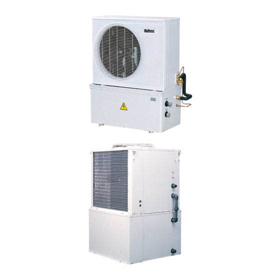
- Page 1 MAC - 2004 Air Cooled Mini Chiller Models: MAC/M4AC 040-058A/AR MAC 075-125B/BR M4AC 040-058AE/ARE M4AC 075-125BE/BRE...
-
Page 2: Table Of Contents
"McQuay" is a registered trademark of McQuay International. All rights reserved throughout the world. 2003 McQuay International "Bulletin illustrations cover the general appearance of McQuay International products at the time of publication and we reserve the right to make changes in design and construction at any time without notice."... -
Page 3: Nomenclature System
Features General The MCQUAY Mini Air Cooled Chillers have been designed to satisfy the most demanding reliability, safety and flexibility required by our customers. The new slim and compact design is available in six sizes, capacity range of 30,000 Btu/h to 125,000 Btu/h. -
Page 4: General Specification
General Specifications Air-Cooler Condenser The air cooled condenser coil is consist of staggered rows of 3/8’’ OD seamless copper tube, mechanically expanded onto die formed aluminum fins to ensure optimum heat exchange capability. Condenser Fan Motor To achieve the high air change requirement, the unit is equip with the high air flow propeller fan which is made of acryl styrene resin. - Page 5 Antifreeze Protection The antifreeze heater is activated if the water leaving temperature falls below 2 C (without glycol) in order to prevent heat exchanger from freezing up. Standard Factory Setting Min Entering Max. Entering Entering Water Temp. C Cooling Mode Heating Mode Antifreeze Electronic Controller Setting...
- Page 6 Microprocessor (For Carel Controller Only) Compact µchiller is a versatile electronic controller as compact as a standard thermostat. M4AC040AE/ARE, M4AC050AE/ARE, M4AC058AE/ARE, M4AC075BE/BRE, M4AC100BE/BRE, M4AC125BE/BRE Only Main Functions Control of water temperature at evaporator inlet (inlet water) Time-based and/or temperature-based defrosting cycles Control of fan speed Full alarm management Can be linked up to serial line for supervisory telemaintenance control...
- Page 7 Alarm Table Display Type Comp. pump Resist. valve alarm high pressure low pressure overload flow detector E1, E2, E3 probe automatic timer eeprom run zero crossing defrosting ON defrosting error antifreeze low ambient temperature low supply voltage high supply voltage eeprom boot discon.
- Page 8 shows the code of the USER parameter that can be modified. Pressing the buttons allows to scroll all USER parameters. Press SEL again to display the required USER parameters and modify its value (with the buttons). Press PRG to store the modified parameters and exit the procedure, while the SEL button allows to return to the USER parameters menu.
- Page 9 Setting DEFAULT PARAMETERS Press the PRG button at chiller start-up to set default parameters. Default parameters are based on FACTORY-set parameters and refer to DIRECT and USER parameters only. When the procedure is over, the display will show dF to confirm the operation. Button Status of the unit Effect after pressing the button...
-
Page 10: Specifications
Specifications Air Cooled Mini Chiller MODEL MAC040A MAC050A MAC058A Btu/hr 30,000 40,000 50,000 NOMINAL COOLING CAPACITY kcal/hr 7,560 10,080 12,600 Watt 8,790 11,720 14,650 MATERIAL Electro-galvanised Mild Steel CASING FINISH Polyester Powder THICKNESS 1,342 (52.8) TOTAL HEIGHT (H) mm (in) 1,032 (40.6) - Page 11 Air Cooled Reverse Cycle Mini Chiller MODEL MAC040AR MAC050AR MAC058AR Btu/hr 30,000 40,000 48,000 NOMINAL COOLING CAPACITY kcal/hr 7,560 10,080 12,100 Watt 8,790 11,720 14,060 Btu/hr 32,000 43,000 50,000 NOMINAL HEATING CAPACITY kcal/hr 8,060 10,840 12,600 Watt 9,380 12,600 14,650 Electro-galvanised Mild Steel MATERIAL CASING...
- Page 12 Air Cooled Mini Chiller MODEL MAC075B MAC100B MAC125B Btu/hr 80,000 100,000 125,000 NOMINAL COOLING CAPACITY kcal/hr 20,160 25,200 31,500 Watt 23,440 29,300 36,630 MATERIAL Electro-galvanised Mild Steel CASING FINISH Polyester Powder THICKNESS TOTAL HEIGHT (H) mm (in) 1,739 (68.5) 1,089 (42.9) UNIT WIDTH (W) mm (in)
- Page 13 Air Cooled Reverse Cycle Mini Chiller MODEL MAC075BR MAC100BR MAC125BR Btu/hr 80,000 94,000 125,000 NOMINAL COOLING CAPACITY kcal/hr 20,160 23,690 31,500 Watt 23,440 27,540 36,630 Btu/hr 93,000 100,000 145,000 NOMINAL HEATING CAPACITY kcal/hr 23,440 25,200 36,540 Watt 27,250 29,300 42,490 Electro-galvanised Mild Steel MATERIAL CASING...
- Page 14 Air Cooled Mini Chiller (R407C) MODEL M4AC040A M4AC050A M4AC058A Btu/hr 30,000 40,000 48,000 NOMINAL COOLING CAPACITY kcal/hr 7,560 10,080 12,100 Watt 8,792 11,723 14,068 MATERIAL Electro-galvanised Mild Steel CASING FINISH Polyester Powder THICKNESS 1,342 (52.8) TOTAL HEIGHT (H) mm (in) UNIT WIDTH (W) mm (in)
- Page 15 Air Cooled Reverse Cycle Mini Chiller (R407C) MODEL M4AC040AR M4AC050AR M4AC058AR Btu/hr 30,000 40,000 48,000 NOMINAL COOLING CAPACITY kcal/hr 7,560 10,080 12,120 Watt 8,790 11,720 14,060 Btu/hr 33,000 43,000 50,000 NOMINAL HEATING CAPACITY kcal/hr 8,320 10,840 12,600 Watt 9,670 12,600 14,650 Electro-galvanised Mild Steel MATERIAL...
- Page 16 Air Cooled Chiller MODEL M4AC040AE M4AC050AE M4AC058AE Btu/hr 30,000 40,000 48,000 NOMINAL COOLING CAPACITY kcal/hr 7,560 10,080 12,100 Watt 8,792 11,723 12,068 Electro-galvanised Mild Steel MATERIAL CASING FINISH Polyester Powder THICKNESS 1,342 (52.8) TOTAL HEIGHT (H) mm (in) UNIT WIDTH (W) mm (in) 1,032 (40.6) 558 (22.0)
- Page 17 Air Cooled Chiller MODEL M4AC075BE M4AC100BE M4AC125BE btu/hr 76000 95000 118750 NOMINAL COOLING CAPACITY kcal/hr 19152 23940 29925 watt 22268 27835 34793 MATERIAL Electro-galvanized Mild Steel CASING FINISH Polyester Powder THICKNESS HEIGHT (H) 1739(1036*) DIMENSION WIDTH (W) 1089(1010*) DEPTH (D) 1288(1187*) WEIGHT NOISE LEVEL...
- Page 18 Air Cooled Chiller MODEL M4AC040ARE M4AC050ARE M4AC058ARE Btu/hr 30000/33000 40000/43000 48000/50000 NOMINAL CAPACITY (COOLING/HEATING) kcal/hr 7560/8316 10080/10836 12100/12600 Watt 8792/9669 11723/12600 12068/14650 Electro-galvanised Mild Steel MATERIAL CASING Polyester Powder FINISH THICKNESS TOTAL HEIGHT (H) mm (in) 1,342 (52.8) UNIT WIDTH (W) mm (in) 1,032 (40.6) 558 (22.0)
- Page 19 Air Cooled Chiller MODEL M4AC075BRE M4AC100BRE M4AC125BRE btu/hr 68240/71652 85300/95536 105772/114302 NOMINALCAPACITY (COOLING / HEATING) kcal/hr 17197/18057 21496/24076 26656/28810 watt 20000/21000 25000/28000 31000/33500 MATERIAL Electro-galvanized Mild Steel CASING FINISH Polyester Powder THICKNESS HEIGHT (H) 1739(1036*) DIMENSION WIDTH (W) 1089(1010*) DEPTH (D) 1288(1187*) WEIGHT NOISE LEVEL...
-
Page 20: Performance Characteristics
7.80 3.45 7.03 3.65 6.42 3.84 10.55 11.05 2.88 3.07 9.72 3.27 8.79 3.41 8.14 3.60 7.33 3.78 6.97 3.97 MAC040A 10.94 11.45 2.96 3.19 10.06 3.40 9.80 3.54 8.52 3.72 7.50 3.86 7.24 4.12 11.29 11.78 3.05 3.28 11.24 3.53... - Page 21 Cooling Heat Pump Version AMBIENT TEMPERATURE ON CONDENSER (°C) MODEL POWER POWER POWER POWER POWER POWER POWER COOL COOL COOL COOL COOL COOL COOL INPUT INPUT INPUT INPUT INPUT INPUT INPUT CAP. CAP. CAP. CAP. CAP. CAP. CAP. 9.40 2.26 8.90 2.41 8.76...
- Page 22 Heating Heat Pump Version AMBIENT TEMPERATURE ON CONDENSER (°C) MODEL HEAT POWER HEAT POWER HEAT POWER HEAT POWER HEAT POWER HEAT POWER HEAT POWER HEAT POWER CAP. INPUT CAP. INPUT CAP. INPUT CAP. INPUT CAP. INPUT CAP. INPUT CAP. INPUT CAP.
- Page 23 Cooling Version AMBIENT TEMPERATURE ON CONDENSER (°C) MODEL COOL POWER COOL POWER COOL POWER COOL POWER COOL POWER COOL POWER COOL POWER CAP. CAP. CAP. CAP. CAP. CAP. CAP. INPUT INPUT INPUT INPUT INPUT INPUT INPUT 23.60 4.63 22.78 5.21 21.55 5.47 21.11...
- Page 24 Cooling In Heat Pump Version AMBIENT TEMPERATURE ON CONDENSER (°C) MODEL COOL POWER COOL POWER COOL POWER COOL POWER COOL POWER COOL POWER COOL POWER CAP. CAP. CAP. CAP. CAP. CAP. CAP. INPUT INPUT INPUT INPUT INPUT INPUT INPUT 25.03 5.83 22.91 5.92...
- Page 25 Heating In Heat Pump Version AMBIENT TEMPERATURE ON CONDENSER (°C) MODEL HEAT POWER HEAT POWER HEAT POWER HEAT POWER HEAT POWER HEAT POWER HEAT POWER HEAT POWER CAP. INPUT CAP. INPUT CAP. INPUT CAP. INPUT CAP. INPUT CAP. INPUT CAP. INPUT CAP.
- Page 26 Cooling Version AMBIENT TEMPERATURE ON CONDENSER (°C) MODEL COOL POWER COOL POWER COOL POWER COOL POWER COOL POWER COOL POWER COOL POWER CAP. CAP. CAP. CAP. CAP. CAP. CAP. INPUT INPUT INPUT INPUT INPUT INPUT INPUT 10.11 2.86 9.50 3.05 8.65 3.24 7.74...
- Page 27 Cooling In Heat Pump Version AMBIENT TEMPERATURE ON CONDENSER (°C) MODEL COOL POWER COOL POWER COOL POWER COOL POWER COOL POWER COOL POWER COOL POWER CAP. INPUT CAP. INPUT CAP. INPUT CAP. INPUT CAP. INPUT CAP. INPUT CAP. INPUT 9.12 2.42 8.63 2.58...
- Page 28 Heating In Heat Pump Version AMBIENT TEMPERATURE ON CONDENSER (°C) M ODE L HEAT POWER HEAT POWER HEAT POWER HEAT POWER HEAT POWER HEAT POWER HEAT POWER HEAT POWER CAP. INPUT CAP. INPUT CAP. INPUT CAP. INPUT CAP. INPUT CAP. INPUT CAP.
- Page 29 Cooling Version AMBIENT TEMPERATURE ON CONDENSER (°C) MODEL COOL POWER COOL POWER COOL POWER COOL POWER COOL POWER COOL POWER COOL POWER CAP. INPUT CAP. INPUT CAP. INPUT CAP. INPUT CAP. INPUT CAP. INPUT CAP. INPUT 22.92 4.95 22.10 5.57 20.90 5.85 20.48...
- Page 30 Cooling Heat Pump Version AMBIENT TEMPERATURE ON CONDENSER (°C) MODEL COOL COOL COOL COOL COOL COOL COOL POWER POWER POWER POWER POWER POWER POWER CAP. INPUT CAP. INPUT CAP. INPUT CAP. INPUT CAP. INPUT CAP. INPUT CAP. INPUT 24.28 6.24 22.22 6.33 21.31...
- Page 31 Heating In Heat Pump Version AMBIENT TEMPERATURE ON CONDENSER (°C) MODEL HEAT POWER HEAT POWER HEAT POWER HEAT POWER HEAT POWER HEAT POWER HEAT POWER HEAT POWER CAP. INPUT CAP. INPUT CAP. INPUT CAP. INPUT CAP. INPUT CAP. INPUT CAP. INPUT CAP.
-
Page 32: Technical Data
Technical Data Evaporator pressure drop and Hydraulic lift MAC/ M4AC040A/AR MAC/ M4AC050A/AR MAC/ M4AC058A/AR M4AC040AE/ARE M4AC050AE/ARE M4AC058AE/ARE Flowrate Pressure drop Hydraulic lift Flowrate Pressure drop Hydraulic lift Flowrate Pressure drop Hydraulic lift (m3/hr) kPa (*) (m3/hr) kPa (*) (m3/hr) kPa (*) 0.72 0.86 1.15... -
Page 33: Outlines And Dimensions
Outlines and Dimensions Model : MAC040 / 050 / 058A/AR, M4AC040 / 050 / 058A/AR Bottom Compartment... - Page 34 Model : MAC075 / 100 / 125B/BR...
- Page 35 Top Compartment Bottom Compartment...
-
Page 36: Wiring Diagrams
Wiring Diagrams Model : MAC040 / 050 A, M4AC040 / 050A (Cooling Only) SYMBOL DESCRIPTION PRINTED CIRCUIT BOARD FLOW SWITCH SWITCH AHTR ANTIFREEZE HEATER WIRE FAN MOTOR COMP COMPRESSOR EARTH Model : MAC058A , M4AC058A (Cooling Only) SYMBOL DESCRIPTION PRINTED CIRCUIT BOARD FLOW SWITCH SWITCH AHTR... - Page 37 Model : MAC040 / 050 / 058AR , M4AC040 / 050 / 058AR (Heat Pump) SYMBOL DESCRIPTION PRINTED CIRCUIT BOARD FLOW SWITCH AHTR ANTIFREEZE HEATER WIRE SWITCH RELAY COMP COMPRESSOR Model : MAC075 / 100 / 125B (Cooling Only) SYMBOL DESCRIPTION COMP.
- Page 38 Model : MAC075 / 100 / 125BR (Heat Pump) SYMBOL DESCRIPTION COMP. COMPRESSOR OUTDOOR FAN 4 WAY VALVE PRINTED CIRCUIT BOARD NOTE : COMP O/L COMPRESSOR OVERLOAD PROTECTOR FOR MAC00B/BR & 125B/BR OF O/L OUTDOOR FAN OVERLOAD PROTECTOR ONLY PUMP O/L PUMP OVERLOAD PROTECTOR HIGH PRESSURE SWITCH PROTECTION LOW PRESSURE SWITCH PROTECTION...
- Page 39 Model : MAC075 / 100 / 125BR (Heat Pump) SYMBOL DESCRIPTION COMP. COMPRESSOR OUTDOOR FAN 4 WAY VALVE NOTE : PRINTED CIRCUIT BOARD FOR MAC100B/BR & 125B/BR COMP O/L COMPRESSOR OVERLOAD PROTECTOR ONLY OF O/L OUTDOOR FAN OVERLOAD PROTECTOR PUMP O/L PUMP OVERLOAD PROTECTOR HIGH PRESSURE SWITCH PROTECTION LOW PRESSURE SWITCH PROTECTION...
- Page 40 Model : M4AC040 / 050 / 058AE SYMBOL DESCRIPTION CAREL CTRL CAREL CONTROLLER FLOW SWITCH SWITCH AHTR ANTIFREEZE HEATER WIRE TRANSFORMER PUMP O/L PUMP OVERLOAD PROTECTOR E.WATER ENTERING WATER SENSOR L.WATER LEAVING WATER / ANTIFREEZE SENSOR COIL TEMPERATURE SENSOR C.TEMP (DEFROST SENSOR) ALARM Model : M4AC040 / 050 / 058ARE...
- Page 41 Model : M4AC075 / 100 / 125BE SYMBOL DESCRIPTION SYMBOL DESCRIPTION COMP. COMPRESSOR FLOW SWITCH NOTE : OUTDOOR FAN SWITCH FOR MAC125BE ONLY CAREL CTRL CAREL CONTROLLER AHTR ANTIFREEZE HEATER WIRE COMP O/L COMPRESSOR OVERLOAD PROTECTOR PHASE PROTECTOR RELAY 240V E.WATER ENTERING WATER SENSOR PUMP O/L...
-
Page 42: Special Precautions For R407C
Special Precautions for R407C Special Precautions When Dealing With Refrigerant R407C Unit 1) What is new refrigerant R407C? R407C is a zeotropic refrigerant mixture which has Zero Ozone Depletion Potential (ODP = 0) and thus conformed to the Montreal Protocol regulation. It requires Polyol-ester oil (POE) oil for its compressor's lubricant. - Page 43 c) Ensure that the compressor is not expose to open air for more than the recommended time specified by its manufacturer (typically less than 10 minutes). Removed the seal-plugs only when the compressor is about to be brazed. d) The system should be thoroughly vacuumed to 1.0 Pa (-700mmHg) or lower. This vacuuming level is more stringent than R22 system so as to ensure no incompressible gas and moisture in the system.
-
Page 44: Installation
Installation Location for Installation In order to achieve maximum cooling capacity, the location selection should fulfill the following requirements: a) Install the chiller in such a way that the hot air discharge cannot be drawn in again. b) Ensure that there is no obstruction to air flow into or out of the unit. Remove obstacles which blocking intake or discharge air. - Page 45 d) Choose a place which can rigidly support the weight of the unit, this will help to minimize vibration and noise. e) The location must not be susceptible to dust or oil to avoid condenser coil being choke by the contaminant.
- Page 46 Installation Clearance It is advised to have sufficient clearance around the unit for proper condenser air flow and to facilitate access for maintenance. (see clearance shown in figure below ) Model MAC040 – 058A 950mm 900mm 900mm MAC040 – 058AR Remarks: Minimum vertical clearance required above the unit is side clearance (A=950mm) should be doubled if two units are installed side by side, or when there are obstructions such as walls.
-
Page 47: Servicing And Maintenance
Servicing and Maintenance Servicing Servicing or maintenance of these unit must be carried out by experienced personnel with specific training in refrigeration. Repeated check the safety devices and continuous cycling of control components must be analyzed and corrected before being reset. The simple design of the refrigeration circuit totally eliminates potential problems during normal unit operation. -
Page 48: Troubleshooting
Troubleshooting When any malfunction is occurred, immediately switch off the power supply to the unit, and contact the local dealer, if necessary. Some simple trouble shooting tips are given below. SYMPTOMS POSSIBLE CAUSES REMEDIAL ACTION 1. Compressor does not start No power supply. -
Page 49: Troubleshooting With Microprocessor
Troubleshooting with Microprocessor (Not Include Carel Controller) Symptoms Possible Causes Remedial Action Compressor thermal relay tripped Reset the thermal relay and carefully monitor unit operation when it is 1. PCB display ‘CO’ restarted Terminal loose Tighten terminal screws. Pump thermal relay tripped Reset the thermal relay and carefully monitor unit operation when it is 2. -
Page 50: Schematic Diagram
Schematic Diagram Refrigerant and Hydraulic Circuit Diagram Cooling Version Model : MAC040 ~ 058A M4AC040 ~ 058AE 1. COMPRESSOR 8. FLOW SWITH 2. HEAT EXCHANGER (CONDENSER) 9. WATER PUMP 3. MOTOR FAN 10. WATER STORAGE TANK 4. THREE WAY VALVES WITH FLARE JOINT 11. - Page 51 Refrigerant and Hydraulic Circuit Diagram Heat Pump Version Model : MAC040 ~ 058AR M4AC040 ~ 058ARE 9. BRAZED PLATE HEAT EXCHANGER 1. COMPRESSOR 2. HEAT EXCHANGER (CONDENSER) 10. FLOW SWITCH 3. MOTOR FAN 11. WATER PUMP 4. THERMOSTATIC EXPANSION VALVE 12.
- Page 52 Cooling (Schematic Diagram) (MAC075B ~ 125B) 1. SCROLL COMPRESSOR 8. CHILLED WATER OUT 2. OUTDOOR HEAT EXCHANGER 9. CHILLED WATER IN 3. FAN MOTOR 10. PUMP 4. FILTER DRIER 11. WATER STORAGE TANK 5. SIGHTGLASS 12. EXPANSION TANK 6. THERMOSTATIC EXPANSION VALVE 13.
- Page 53 Heat Pump (Schematic Diagram) (MAC075 ~ 125BR) 1. SCROLL COMPRESSOR 9. SUCTION ACCUMULATOR 2. 4 WAY VALVE 10. BPHE 3. HEAT EXCHANGER 11. CHILLER WATER OUT 4. FAN MOTOR 12. CHILLER WATER IN 5. FILTER DRIER 13. PUMP 6. CHECK VALVE 14.
- Page 54 Refrigerant Circuit Diagram Model : M4AC075BRE, 100BRE, 125BRE...
-
Page 55: Parts List And Exploded View
Parts List and Exploded View Model : MAC/ M4AC040 ~ 058A/AR (Top Compartment) 1. BASE PAN ASSY. 8. FAN BLADE 2. ACCESS/SERVICE PANEL 9. FRONT PANEL ASSY. 3. CONDENSER COIL ASSY. 10. SIDE PANEL LEFT 4. COMPRESSOR 11. TERMINAL BOX ASSY. 5. - Page 56 (Bottom Compartment) 1. BASE PAN ASSY. 8. WATER STORAGE TANK 2. BPHE BRACKET 9. SIDE PANEL RIGHT 3. BPHE CLAMP 10. SIDE PANEL LEFT 4. BRAZED PLATE HEAT EXCHANGER 11. FRONT PANEL 5. WATER PUMP 12. REAR PANEL 6. TERMINAL BOX ASSY. 13.
- Page 57 Model : MAC/ M4AC075 ~ 125B/BR 1. ASSY. BASE PAN 13. ASSY. STRUCTURE BACK RIGHT 2. SCROLL COMPRESSOR 14. PLATE. ORIFICE 3. BRACKET BPHE 15. FAN MOTOR 4. ASSY. BPHE 16. BRACKET FAN MOTOR 6. CLAMP TUBE 17. FAN BLADE 7.
- Page 58 1. ASSY. BASE PAN H 6. ASSY. PANEL SIDE LEFT H 2. ASSY. WATER STORAGE TANK 7. PANEL. FRONT SIDE H 3. ASSY. SUPPORT PILAR H 8. PANEL REAR H 4. ASSY. MAIN STRUCT. FRONT RIGHT 9. PANEL TOP H 5.
- Page 59 REGISTERED ISO 9002 ©2004 McQuay International +1 (800) 432-1342 www.mcquay.com...
Need help?
Do you have a question about the MAC040A and is the answer not in the manual?
Questions and answers