Table of Contents
Advertisement
Quick Links
- 1 Connect the Distributed Modular I/O Master Block
- 2 M12 Network Port
- 3 Tell the Controller about the Device
- 4 Using Electronic Data Sheet (Eds) Files
- 5 Troubleshooting Tips
- 6 Confirm Communication Is Established
- 7 Configure Io-Link Ports for Distributed Modular I/O
- 8 Io-Link Ports – Output Data
- Download this manual
Advertisement
Table of Contents

Related Manuals for Balluff BNI004A


Summary of Contents for Balluff BNI004A
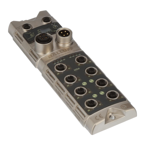
- Page 1 Distributed Modular I/O Quick Start Guide for 4 port IO-Link Master BNI004A BNI EIP-502-105-Z015 Discrete Power Quick Start Guide RFID or Discrete Analog Valve Manifold Specialty Control Devices...
- Page 2 Connect the Distributed Modular I/O Master Block 1. Using an M12 D-coded EtherNet/IP cable, connect the block to the Ethernet network. 2. Power up the block using 24VDC and a 7/8" 4pole connector wired according to the below diagram. 3. Set the IP address of the block using the pushbutton display. For instructions on operating the display, see the manual. M12 Network Port Function Description...
- Page 3 Data length: how much data to expect at this location, these are 8bit, 1byte short integers. For controllers that read in 2byte words or in individual bit counts, please see the Balluff website for the data assistance spreadsheet. The EDS file in RSLogix5000 Ver 20...
- Page 4 Confirm Communication is Established It is important to confirm the device is talking to the controller; this can be done by verifying status lights on the block just below the aux power ports and just above the first M12 I/O ports. Functional Depending on which Solid green at 100Mbps, off if using 10Mbps...
- Page 5 Configure IO-Link Ports for Distributed Modular I/O Once communication is established you now need to tell the device how it will be used for Distributed Modular I/O. Every port can be used for standard I/O and is defaulted to this configuration. To tell the master block to look for an IO-Link device, there are some configuration bytes that must be setup.
- Page 6 Reading the Process Data – Inputs It is important to note that every standard I/O on the block Standard Input Data (bytes of data in the input buffer of the master block) is setup as a freely configurable port. If the controller is Description Byte Bit (block pin #)
- Page 7 Reading the Process Data – Outputs It is important to note that every standard I/O on the block is setup as a freely configurable port. If the controller is programmed to look for an input and there is an input wired there, it will be an input. If the controller is programmed to fire an output, it will be an output there. There are diagnostic inputs available that will indicate an overload on an output from the master block.
Need help?
Do you have a question about the BNI004A and is the answer not in the manual?
Questions and answers