Table of Contents
Advertisement
Quick Links
Advertisement
Table of Contents

Related Manuals for Balluff BNI EIP-104-005-E002


Summary of Contents for Balluff BNI EIP-104-005-E002
- Page 1 BNI EIP-104-005-E002 BNI EIP-302-005-E002 EtherNet/IP IP69 Modules User's Guide...
-
Page 2: Table Of Contents
Rockwell Automation products that are compatible with QuickConnect Example with Rockwell Components PLC Program Fault State Enable/Disable Fault State Fault State Action Process data Data Configuration BNI EIP-302-005-E002 7.1. Process Data Inputs BNI EIP-302-005-E002 7.2. Process Data Outputs BNI EIP-302-005-E002 www.balluff.com... - Page 3 Balluff Network Interface EtherNet/IP™ Data Configuration BNI EIP-104-005-E002 7.3. Process Data Inputs BNI EIP-104-005-E002 7.4. Process Data Outputs BNI EIP-104-005-E002 Web Server 8.1. General Information 8.2. Navigation / Info 8.3. Login/Logout 8.4. "Home" dialog 8.5. "Config" dialog 8.6. "Log" dialog Appendix 9.1.
-
Page 4: General Information
Cross-references indicate where additional information on the topic can be found. 1.3. Symbols Note This symbol indicates general notes. Attention! This symbol indicates a security notice which must be observed. 1.4. Abbreviations Balluff Network Interface Standard input port EtherNet/IP™ Electromagnetic compatibility Function ground Standard output port 1.5. Deviating views Product views and illustrations in this user's guide may differ from the actual product. -
Page 5: Safety
Before maintenance, disconnect the device from the power supply. Note In the interests of product improvement, Balluff GmbH reserves the right to change the technical data of the product and the content of this manual at any time without notice. -
Page 6: First Steps
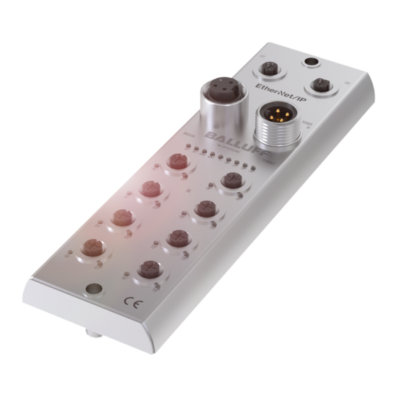
Power IN Port 04 / 05 Status LED: communication / module Port 02 / 03 Port 08 / 09 Port 00 / 01 Pin/port LED: signal status Power OUT Port 10 / 11 EtherNet/IP™ port 1 Port 12 / 13 www.balluff.com... -
Page 7: Mechanical Connection
Balluff Network Interface EtherNet/IP™ First Steps 3.2. Mechanical The module is secured by means of two M6 screws and two washers. Connection Insulation support is available separately. 3.3. Electrical Connection Power Supply Function Description +24 V Actuator supply +24 V Module / sensor supply 7/8”, male... -
Page 8: I/O Port
For the digital sensor inputs, refer to guideline on inputs EN 61131-2, Type 2. Note Each output receives a maximum current of 2 A. The total current of the module must not exceed 9 A. Note Unused I/O ports must be provided with cover caps to comply with degree of protection IP69. www.balluff.com... -
Page 9: Technical Data
Balluff Network Interface EtherNet/IP™ Technical Data 4.1. Dimensions 4.2. Mechanical Data Housing material Stainless steel (V4A) Enclosure rating per IEC 60529 IP 69 (only when plugged-in and threaded-in) Dimensions (W x H x D in mm) 70 x 228 x 44.1... -
Page 10: Ethernet
I/O status The status of the input or output pins is 0 Yellow I/O status The status of the input or output pins is 1 Red, Short-circuit Short-circuit between pin 1 and 3 flashing Short-circuit Short-circuit at dedicated pin www.balluff.com... -
Page 11: Integration
Balluff Network Interface EtherNet/IP™ Integration 5.1. Integration in Here you see an example of how the module can be integrated into a Rockwell RS Logix Rockwell RS 5000: Logix 5000 First go offline Right-click Ethernet (on the correct scanner card) Select a new module www.balluff.com... - Page 12 Integration Then select the general Ethernet module as the ETHERNET module in the communication path Now enter a user-defined tag name to select the Data-SINT general format, enter the IP address of the module and the correct connection parameters. www.balluff.com...
- Page 13 Balluff Network Interface EtherNet/IP™ Integration The new module and corresponding controller tags are generated automatically. Then download the configuration www.balluff.com...
-
Page 14: Address Specifications
Make sure you select the correct tag name, which you configured beforehand. The input, output and configuration data for this is described on the following pages. You can use these tags for the programming, too. 5.2. Address These settings are factory-set. Specifications IP-Adresse: 192.168.1.1 Subnetmaske: 255.255.255.0 Gatewayadresse: 192.168.1.1 www.balluff.com... -
Page 15: Configuration Via Explicit Messages
Balluff Network Interface EtherNet/IP™ Configuration via Explicit Messages QuickConnect The modules BNI EIP-302-005-E002 and BNI EIP-104-005-E002 can be started up and incorporated faster using the QuickConnect function. Enabling QuickConnect automatically takes over all necessary port properties on the module: •... -
Page 16: Rockwell Automation Products That Are Compatible With Quickconnect
Configuration via Explicit Messages Rockwell Automation products that are compatible with QuickConnect Source: Allen-Bradley Ethernet/IP QuickConnect Application Technique Page 13 www.balluff.com... -
Page 17: Example With Rockwell Components
Balluff Network Interface EtherNet/IP™ Configuration via Explicit Messages Example with Rockwell Components Source: Allen-Bradley Ethernet/IP QuickConnect Application Technique, Page 12 Please also note the following: • Direct connection between PLC and QuickConnect slave with crossover cable • Slave-to-slave connection using patch cable •... -
Page 18: Plc Program
Configuration via Explicit Messages PLC Program Source: Allen-Bradley Ethernet/IP QuickConnect Application Technique, Page 29 www.balluff.com... - Page 19 Balluff Network Interface EtherNet/IP™ Configuration via Explicit Messages Source: Allen-Bradley Ethernet/IP QuickConnect Application Technique, Page 30 www.balluff.com...
- Page 20 Configuration via Explicit Messages Source: Allen-Bradley Ethernet/IP QuickConnect Application Technique, Page 31 www.balluff.com...
-
Page 21: Fault State
Balluff Network Interface EtherNet/IP™ Configuration via Explicit Messages Source: Allen-Bradley Ethernet/IP QuickConnect Application Technique, Page 32 Fault State A safe state that the port is to take on in the case of a loss of bus communication can be predefined for each output on the port pins. -
Page 22: Process Data
Output data Output on Port 0, Pin 4 Restart Restart of the output after a short- circuit is detected Reserved Display control DL: Display disabled / PLC disable GO: Green display LED on RO: Red display LED on www.balluff.com... -
Page 23: Data Configuration
Balluff Network Interface EtherNet/IP™ Process data Data Please enter the following values in the control system. These describe the data size for Configuration input/output and configuration data. BNI EIP-104-005- E002 Instance ID Data length INPUT OUTPUT 7.3. Process Data The input data size is 6 bytes. Take a look at the tables below for the allocation of the Inputs process data inputs. -
Page 24: Web Server
For open a connection with the web server, enter the IP address of the module in the address line of the browser. The homepage then appears with the essential device information. www.balluff.com... -
Page 25: Navigation / Info
The navigation bar is located in the upper area of the window, which allows you to switch between the various dialogs of the web interface. To do this click on the corresponding icon. When the "Info" tab is selected the following overview appears: The "BALLUFF" logo at upper right links to the international Balluff homepage. www.balluff.com... -
Page 26: Login/Logout
Webserver the user is automatically logged out. Note For security reasons the fieldbus module shows only one login at a time with configuration access. Reading (without logging in) is however possible from multiple PCs at the same time on the fieldbus module. www.balluff.com... -
Page 27: Home" Dialog
Balluff Network Interface EtherNet/IP™ Web Server 8.4. "Home" dialog Under "Home" you are given the essential information about the fieldbus itself and its network activity. You are also shown whether the configuration block was enabled by the controller (PLC). Information is also shown about the current process data and the status of the module via the corresponding LEDs. - Page 28 Web Server PNT: EIP: www.balluff.com...
-
Page 29: Config" Dialog
Balluff Network Interface EtherNet/IP™ Web Server 8.5. "Config" dialog The configuration page enables configuration of the module. You can change the module information texts and the (for EIP) IP-Configuration. PNT / ECT: www.balluff.com... - Page 30 The "Reboot" button reboots the device as if the power to the module had been turned off and on again. Clicking on "Factory Reset" deletes the configuration and log files saved in the device and then performs a reboot, so that the device is restored to the default factory configuration as on delivery. www.balluff.com...
-
Page 31: Log" Dialog
After a reset, reboot or loss of power the time begins to run again from the year 2000. Clicking on "Update Log” refreshes the display, and "Clear Log” deletes all entries. The log entries are stored in a ring buffer. www.balluff.com... -
Page 32: Appendix
Appendix 9.1. Order number BNI EIP-xxx-005-E002 Balluff network interface Ethernet IP Functions 302 = IP 69 Input/Output Module 104 = IP 69 Input Module Variants 005 = 2-Port-Switch Mechanical Version E002 = stainless steel housing V4A Data transmission: 2 x M12x1 internal thread Power supply: 7/8"... -
Page 33: Notes
Notes www.balluff.com... - Page 34 Balluff GmbH Schurwaldstrasse 9 73765 Neuhausen a.d.F. Germany Tel. +49 7158 173-0 Fax +49 7158 5010 www.balluff.com balluff@balluff.de...
Need help?
Do you have a question about the BNI EIP-104-005-E002 and is the answer not in the manual?
Questions and answers