Table of Contents
Advertisement
Advertisement
Table of Contents

Related Manuals for Balluff BNI IOL-719-002-Z012


Summary of Contents for Balluff BNI IOL-719-002-Z012
- Page 1 BNI IOL-719-002-Z012 User´s Guide...
-
Page 2: Table Of Contents
3.10. Dimensioned data format IO-Link Interface 4.1. IO-Link Data 4.2. Prozess data / Input data BNI IOL-719-002-Z012 4.3. Process data / Output data BNI IOL-719-002-Z012 4.4. Parameter data / Request data Setting the serial number 54hex Process data alignment 59hex... - Page 3 Balluff Network Interface / IO-Link BNI IOL-719-002-Z012 5.4. Operating conditions 5.5. LED indicators Status LEDs LED I-Ports Standard Appendix 6.1. Product ordering code 6.2. Order information Included material www.balluff.com...
-
Page 4: Notes For The User
Cross references indicate where additional information on the topic can be found. 1.3. Symbols Attention! This symbol indicates a security notice which must be observed. Note This symbol indicates general notes. 1.4. Abbreviations Balluff Network Interface Direct Parameter Page Electromagnetic Compatibility Function Earth IO-Link ISDU Index Service Data Unit Most significant bit 1.5. -
Page 5: Safety
Safety 2.1. Intended use This guide describes the Balluff Network Interface BNI IOL-719-002-Z012 for the application as peripheral analog input module to establish connection of analog sensors, RTDs and thermocouple sensors. Hereby it is about an IO-Link device which communicates by means of IO-Link protocol with the superordinate IO-Link master assembly. -
Page 6: Getting Started
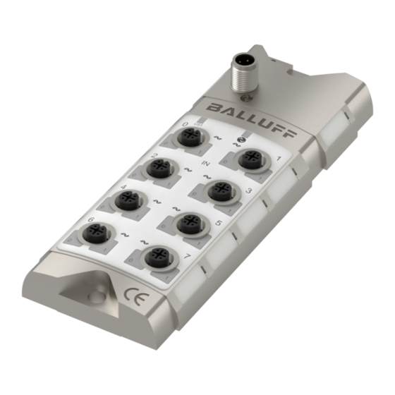
Getting Started 3.1. Connection overview Fig. 3-1: BNI IOL-719-002-Z012 1 Mounting hole 9 Pin/Port LED: Signalstatus 2 Label 10 Analog port 6 3 Status LED: Communication 11 Analog port 4 4 Analog port 1 12 Analog port 2 5 Analog port 3... -
Page 7: Mechanical Connection
Balluff Network Interface / IO-Link BNI IOL-719-002-Z012 Getting Started 3.2. Mechanical The BNI IOL-719-002-Z012 modules are attached by using 2 M6 screws and 2 spacers. connection 3.3. Electrical The BNI IOL-719-002-Z012 modules require no separate supply voltage connection. Power connection is provided through the IO-Link interface by the host IO-Link Master. -
Page 8: Functionality
Getting Started 3.4. Functionality The BNI IOL-719-002-Z012 module has eight free configurable analog port. The ports can be configured independently to accept voltage signal, current signal, Pt sensor or thermocouples. Input type Nominal range Voltage 0 V - 10 V... -
Page 9: Sensor Interface
The short circuit error is latched and it can be reset with the output process data. Note In case of current input, the BNI IOL-719-002-Z012 works only with 3-wire sensors. www.balluff.com... - Page 10 Getting Started PT100 BNI IOL-719-002-Z012 Sensor Interface 2-wire 3-wire 4-wire Attention! A care must be taken during wiring. The inputs are protected against wrong wiring, but in some special cases damage can be occurred. Be sure to connect the wiring properly before turning power supply on.
-
Page 11: Input Signal Range
(grounded) 3.7. Data formats The signal on the input port of the BNI IOL-719-002-Z012 will be digitalized and sent as a process data over IO-Link. There are 16 bits reserved in the process data for each port. The digitalized value can be represented in different formats (signed, unsigned or dimensioned), in different resolution (16, 14, 12 or 10 bit), with different alignment (left or right aligned). -
Page 12: Signed Data Format
0, so it is a positive number. In this case the voltage can be calculated with the following formula: 10.5�� Input voltage [ V ] = PortValue ∗ = 4660 ∗ = 5,974�� ( N−1 ) − 1 ( 14−1 ) − 1 www.balluff.com... -
Page 13: Unsigned Data Format
(FFFF in case of 16 bit resolution). The input signal on the BNI IOL-719-002-Z012 can be calculated from the digital value with the following formulas: Voltage input (0V-10V, 5V – 10V, -10V - +10V, 0V - 5V, -5V - +5V): −... - Page 14 The resolution is 16 bit The digitalized value read over IO-Link is 4567hex = 17767 −T 1200°��− ( −100°�� ) Temperature [ °C ] = PortValue ∗ = 17767 ∗ + ( −100°C ) = 252.44 °�� −1 −1 www.balluff.com...
-
Page 15: Dimensioned Data Format
Balluff Network Interface / IO-Link BNI IOL-719-002-Z012 Getting Started 3.10. Dimensioned In case of dimensioned format, the measured voltage, current or temperature will be data format converted to mV, uA or °C (in 0.1 °C step), and this value will be sent as a process data. In this case the resolution and process data alignment settings do not influence the data. - Page 16 The analog mode is set to TypJ Thermocouple. The digitalized value read over IO-Link is 06F1hex = 1777 In case of Thermocouple input, the dimensioned value has the dimension of 0.1 °C PortValue 1777 Temperature [ °C ] = = 177.7 °�� www.balluff.com...
-
Page 17: Io-Link Interface
Process data cycle time* 55 ms 1320 ms * by min. cycle time Note It is recommended to use the BNI IOL-719-002-Z012 with an IO-Link 1.1 master. In case of IO-Link 1.0 master, the process data cycle time will be extreme high. www.balluff.com... -
Page 18: Prozess Data / Input Data
The switch point bits show a switch point overrun. The switch point can be configured by parameter. (see "Switch Point Enable", "Switch Point 1" and "Switch Point 2") Byte Analog value Port 0 Byte Analog value Port 1 Byte Analog value Port 2 Byte Analog value Port 3 www.balluff.com... - Page 19 Balluff Network Interface / IO-Link BNI IOL-719-002-Z012 IO-Link Interface Byte Analog value Port 4 Byte Analog value Port 5 Byte Analog value Port 6 Byte Analog value Port 7 www.balluff.com...
-
Page 20: Process Data / Output Data
The short circuit error is latched and it can be reset with a 0 -> 1 transition on the corresponding bit in the output process data. www.balluff.com... -
Page 21: Parameter Data / Request Data
Balluff Network Interface / IO-Link BNI IOL-719-002-Z012 IO-Link Interface 4.4. Parameter data ISDU / Request data Object name Length Range Default value Sub- Index Index Index Vendor ID 2 bytes 0378 Device ID 3 bytes 050204 Vendor name 7 bytes... -
Page 22: Setting The Serial Number 54Hex
In case of 10, 12 or 14 bit resolution the analog value is padded with zeros in order to fill the 16 bit in the process data. The justification of the 10, 12 or 14 bit value can be set in Process data alignment ISDU register. 0 = Left justified 1 = Right justified www.balluff.com... - Page 23 Balluff Network Interface / IO-Link BNI IOL-719-002-Z012 IO-Link Interface Analog values in process data in case of left justification for different resolutions. Byte 10 bit analog value 12 bit analog value 14 bit analog value 16 bit analog value Analog values in process data in case of right justification for different resolutions.
-
Page 24: Analog Mode F0Hex
Changing the analog mode of the port to voltage or current input, +24V will be switched between pin1 and pin 3, in order to supply the analog sensor. Be sure, that no Pt100 or Pt1000 sensor is connected to the analog port. The +24V supply voltage can damage the RTD sensor. www.balluff.com... -
Page 25: Resolution F1Hex
Balluff Network Interface / IO-Link BNI IOL-719-002-Z012 IO-Link Interface Resolution The resolution of the analog value can be set with this ISDU register. Accessing the ISDU register through the subindex 0, the resolution for all ports can be read/written. Accessing the ISDU register through subindex 1-8, the resolution for the... -
Page 26: Pt100/Pt1000 Mode F3Hex
Byte Wire break In case of Pt 100, Pt1000, Typ J and Typ K the BNI IOL-719-002-Z012 can detect wire break disable F4 condition. In some cases with a calibrator unit, the wire break detection will be activated. In order to be able to use calibrator to calibrate the module, the wire break detection can be disabled. -
Page 27: Switch Point 1, F6Hex Switch Point 2, F7Hex
Balluff Network Interface / IO-Link BNI IOL-719-002-Z012 IO-Link Interface Switch point Two switch points can be set for each port. When the analog value is greater than the value of 1, F6 the switch point, the corresponding bit in the process data will be set. -
Page 28: Hex
Wire break detected on some port IO-Link Revision 1.1 Event Code Description 0x5111 Low supply voltage (US1) 0x7710 Short circuit on pin1 (on at least one of the ports) 0x8C20 Measurement value is out of range 0x7700 Wire break detected on some port www.balluff.com... -
Page 29: Technical Data
Balluff Network Interface / IO-Link BNI IOL-719-002-Z012 Technical Data 5.1. Dimensions 5.2. Mechanical Housing material Die-cast zinc housing Data IO-Link-Port M12, A-coded, male, Analog Ports M12, female, 5-poles Enclosure rating per IEC 60529 IP67 (only when plugged in and threaded in) Weight ca. -
Page 30: Led Indicators
Indicator Function Port LED Standard Port is switched off Yellow static (LED0) Port is switched on, input signal is in range Red (LED0) Input signal is out of range Red (LED0, LED1) Pin1 short circuit or wirebreak on port www.balluff.com... -
Page 31: Appendix
Balluff Network Interface / IO-Link BNI IOL-719-002-Z012 Appendix 6.1. Product BNI IOL-719-002-Z012 ordering code Balluff Network Interface IO-Link Interface Functions 719 = 8 analog inputs Versions 002 = Base version, IO-Link V1.1 Mechanical design Z012 = Die-cast zinc housing, matte nickel plated... - Page 32 Balluff GmbH Schurwaldstrasse 9 73765 Neuhausen a.d.F. Germany Tel. +49 7158 173-0 Fax +49 7158 5010 www.balluff.com balluff@balluff.de...
Need help?
Do you have a question about the BNI IOL-719-002-Z012 and is the answer not in the manual?
Questions and answers