Table of Contents
Advertisement
Quick Links
Advertisement
Table of Contents

Related Manuals for Balluff BNI00E7


Summary of Contents for Balluff BNI00E7
- Page 1 BNI CIB-508-105-Z015 CC-Link IE Field Basic IO-Link-Master User's Guide...
-
Page 3: Table Of Contents
Table of contents Table of contents General Structure of the guide Typographical conventions Enumerations Actions Syntax Cross-references Symbols Abbreviations Deviating views Safety Intended use Installation and startup General safety notes Resistance to aggressive substances Dangerous voltage First steps Module overview Port Mechanical connection Electrical connection... - Page 4 Error codes for Processing parameter Troubleshooting Indicator LEDs Display in the process data Error list Technical data Dimensions Mechanical data Operating conditions Electrical data CC-Link IE Field Basic Function indicators Module status Port LED Appendix Scope of delivery Order code Ordering information Notes www.balluff.com...
-
Page 5: General
Balluff Network Interface CC-Link IE Field Basic General Structure of the This guide is arranged so that one section builds upon the other. guide Chapter 2: Basic safety instructions Chapter 3: First steps ….… Typographical The following typographical conventions are used in this manual. -
Page 6: Safety
Before working on the device, switch off its power supply. Note In the interest of continuous improvement of the product, Balluff GmbH reserves the right to change the technical data of the product and the content of these instructions at any time without notice. -
Page 7: First Steps
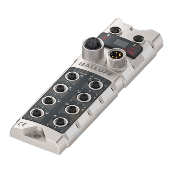
Balluff Network Interface CC-Link IE Field Basic First steps Module overview 1 Ground connection 10 Mounting hole 2 CC-Link IE Field Basic Port 1(L/A1) 11 CC-Link IE Field Basic Port 2 (L/A2) 3 Display 12 Labels 4 Power Out 13 Power In... -
Page 8: Port
► Therefore always use separately protected voltage supplies for sensors and actuators. Also be sure to sufficiently dimension the voltage supply of the device in order to cover startup and peak currents. Design the fusing concept accordingly. www.balluff.com... -
Page 9: Function Ground
Balluff Network Interface CC-Link IE Field Basic First steps Function ground Note The FE-connection from the housing to the machine must have low impedance and be as short as possible. We recommend using the included ground strap for the FE connection. -
Page 10: Display
10 seconds of inactivity. • Display: When interacting using the keys, the respective menu point is displayed. Inactivity causes the standard view to be shown and the set station number displayed. Start-up Module name Hard- and firmware version Station address/IP address www.balluff.com... -
Page 11: Main Menu
Balluff Network Interface CC-Link IE Field Basic Display Main menu Standard view: Station address/IP address display Menu: Network configuration Menu: Module info Menu: Number of occupied stations Menu: Factory setting • Press the Set key briefly to scroll through the main menu. -
Page 12: Menu Point: Number Of Occupied Stations
(Display Locked) to block Edit mode. • Menu point: Hold down the Set key for min. 3 seconds. • Factory Confirm the security prompt by briefly pressing the settings Set key. • The module was reset to its factory default settings. www.balluff.com... -
Page 13: Integration
Balluff Network Interface CC-Link IE Field Basic Integration General The module is used as a remote I/O module and/or IO-Link module for connecting to a CC- Link IE Field Basic network. In the following an example is used to explain how the module can be incorporated into a network with a Mitsubishi Master Station. -
Page 14: Network Configuration Settings
After configuration is complete, the setting must still be saved. Click on "Close with Reflecting Setting" and in the settings window click on "End" to apply the settings there as well. Adjust Refresh Parameters" accordingly. Then load the configuration into the controller. The controller must then be restarted. www.balluff.com... -
Page 15: Csp+-File (Network Configuration Settings)
Balluff Network Interface CC-Link IE Field Basic Integration CSP+-file To start up the CIB module, all that is (network needed is the general profile of an configuration Intelligent Device Station from the module settings) list. If however you wish to use custom... -
Page 16: Cc-Link Ie Field Basic
Ethernet cable 100Base-T Standard: Category 5e or higher Connection cable (double shielded recommended) Maximum distance between 100m max. (ANSI/TIA/EIA-568-B, Category 5e) stations Total cable length Star: Depends on system configuration CIB module Element Specification Maximum number of occupied stations www.balluff.com... -
Page 17: Pin-Port Numbering And Addressing
Balluff Network Interface CC-Link IE Field Basic CC-Link IE Field Basic Pin-port The following table provides information about the association of the labeling on the module numbering and (port and label) and the specific assignment for pin and process data (Register). -
Page 18: State Machine
There is no IO-Link of IO process data communication here. The "Operation condition setting completion“ flag is set to "1". This indicates that reconfiguration is finished. Resetting the "Operation condition setting request“ flag to "0" causes the IO-Link gateway to start communication using the new configuration. www.balluff.com... -
Page 19: Cyclical Transmission
Balluff Network Interface CC-Link IE Field Basic Cyclical transmission General Cyclic data transmission is divided into a bit and a word area. CC-Link IE Field Basic is based on stations, whereby each station incorporates 64 bits and 32 words. The BNI CIB module can be configured for between 2 and 5 stations and thereby offers various process data sizes of 8 to 32 bytes. - Page 20 IO-Link Port 6 Data Valid RY(m+1)06 IO-Link Port 6 Byte Swap Flag RX(m+1)07 IO-Link Port 7 Data Valid RY(m+1)07 IO-Link Port 7 Byte Swap Flag – – RX(m+1)08 RY(m+1)08 Reserved Reserved RX(m+1)3F RY(m+1)3F m = assigned module station number www.balluff.com...
-
Page 21: Details
Balluff Network Interface CC-Link IE Field Basic Cyclical transmission Details Signal name Description Direction: Slave Master (CIB PLC) Input X 0-F (port 0-7, Digital input signal for the corresponding pin (high active, active if 1, pin 2/4) inactive if 0) -
Page 22: Word Range Rwr And Rww
Input process data RWw(m+1)14 Output process data RWr(m+1)1B IO-Link port 6 RWw(m+1)1B IO-Link port 6 – – RWr(m+1)1C Input process data RWw(m+1)1C Output process data RWr(m+2)03 IO-Link port 7 RWw(m+2)03 IO-Link port 7 m = assigned module station number www.balluff.com... - Page 23 Balluff Network Interface CC-Link IE Field Basic Cyclical transmission 4 assigned Register Register Slave Master Master Slave stations – – RWrm00 Status Area RWwm00 Operation Area (24 bytes per RWrm03 RWwm03 channel) – – RWrm04 Input process data RWw04 Output process data...
-
Page 24: Details: Module Status Area
If Byte Swap is disabled, the process data are represented as follows: Word Address High Byte Low Byte RWwm00 IOL PD Byte 1 IOL PD Byte 0 RWwm01 IOL PD Byte 3 IOL PD Byte 2 RWwm02 IOL PD Byte 5 IOL PD Byte 4 … … … www.balluff.com... - Page 25 Balluff Network Interface CC-Link IE Field Basic Cyclical transmission Initializing The CIB module starts up with an "Initial processing" mechanism. This initialization is normally handled by function blocks. If there are no function blocks, the following procedure should be followed: Settings for the IO-Link master can be made directly in the process data.
- Page 26 While the Operation Condition Request flag is set no IO-Link communication takes place. Outputs are disabled and inputs are not read. Settings can be made just as is possible during the Initial Processing phase. The operation condition setting completion flag indicates that the configuration was successfully applied. www.balluff.com...
- Page 27 Balluff Network Interface CC-Link IE Field Basic Cyclical transmission Error/warning Errors or warnings are indicated by the status bits "Error status" and "Warning status". When an handling error occurs, "Ready" is reset. Once the error has been remedied and cleared, the module uses "Ready"...
- Page 28 The CIB module supports "Parameter Processing of Slave Station“. This uses the acyclical part Parameter Processing of the SLMP specification. (Not to be confused with stand-alone SLMP devices.) Entry is the same as in 5.2. Network Parameters. Now select "Network Configuration Settings". Right-click on the device previously detected using "Detect Now". www.balluff.com...
- Page 29 Balluff Network Interface CC-Link IE Field Basic Parameter Processing Now select Online → Parameter Processing of Slave Station. The following window should open: Use the drop-down menu "Method Selection" to select whether you want to read or write parameters. Clicking on the "Execute" button either reads or writes all the selected parameters.
- Page 30 CIB module gives you the turn-off time. gives you the tolerance of the processing time of the CIB module. Or in this example from the illustration approx. 100ms * 3 ~ 300ms. These times are freely selectable for the up to four groups in the CC-Link IE Field Basic network. www.balluff.com...
- Page 31 Balluff Network Interface CC-Link IE Field Basic Parameter Processing Initial Operation Setting: In the default device setting the CIB module always starts in "Initial Operation" mode, i.e. the configuration state. If you want to have all the configuration data loaded from the process data image (e.g.
- Page 32 The following parameters are used for identification of the IO-Link devices (also shown in the parameter image): • Vendor ID: (2 bytes) Vendor-specific identification number, for example for Balluff IO-Link devices 0x0378 Can be read from the IO-Link device using the DPP (Direct Parameter Page) Index range: 0x07-0x08 •...
- Page 33 Balluff Network Interface CC-Link IE Field Basic Parameter Processing Each IO-Link port/channel has a structure with Device Validation. In this case the parameter groups: • Device Validation Port 0 • Device Validation Port 1 • Device Validation Port 2 •...
- Page 34 Cause: parameters were written simultaneously from more than one Engineering Tool, or there was an error in the Engineering Tool • SLMP_ERROR_WRONG_DATA: The received data are incorrect, such as wrong port number. For example a value is read/ written for port 9 even though no such port exists. www.balluff.com...
- Page 35 Balluff Network Interface CC-Link IE Field Basic Troubleshooting Indicator LEDs The LEDs on the module indicate the status of the module and its ports. The following situations may occur: Error indicator Description / Procedure There is undervoltage on the US/UA supply.
- Page 36 0xD529 Gateway Major Internal SW error. 0xD52B Gateway Major MAC initialization failed 0xE243 Gateway Moderate IO-Link port is wrong Incorrect parameter value in the SLMP 0xE119 Gateway Moderate telegram 0xE118 Gateway Moderate Incorrect Device Validation type www.balluff.com...
- Page 37 Balluff Network Interface CC-Link IE Field Basic Technical data Dimensions Mechanical data Housing material Zinc die-casting, matte nickel-plated Enclosure rating per IEC 60529 IP 67 (only in plugged-in and screwed-down state) Supply voltage 7/8", 5-pin, male and female Input ports / output ports...
- Page 38 Technology Ethernet Basic Connection M12, D-coded IEEE 802.3 100 Base-T and ANSI/TIA/EIA- Cable type 568-B (Category 5e) 4 pairs of shielded cable. Double-shielded cable recommended. Data transfer rate 100 Mbps Max. cable length between stations Up to 100 m www.balluff.com...
- Page 39 Balluff Network Interface CC-Link IE Field Basic Technical data Function indicators Status LEDs Port LEDs Module status Status Function No supply voltage Green Sensor supply OK Sensor supply less than 18 V No supply voltage Green Actuator supply OK Red, flashing...
- Page 40 508 = IP 67 SIO + IOL module, max. 16 in-/outputs, max. 8 IO-Link connections Variants 105 = Display version Mechanical version Z015 = Die-cast zinc housing Material: 1. Balluff housing version Bus: 2 x M12x1 internal thread Power port: 7/8" external thread I/O ports: 8 x M12x1 internal thread Ordering...
- Page 41 Balluff Network Interface CC-Link IE Field Basic Notes www.balluff.com...
- Page 42 Balluff GmbH Schurwaldstrasse 9 73765 Neuhausen a.d.F. Germany Tel. +49 7158 173-0 Fax +49 7158 5010 www.balluff.com balluff@balluff.de...
Need help?
Do you have a question about the BNI00E7 and is the answer not in the manual?
Questions and answers