Raymarine gs series Installation Instructions Manual
Hide thumbs
Also See for gs series:
- Installation and operation instructions manual (438 pages) ,
- Installation and operation instructions manual (208 pages)

Related Manuals for Raymarine gs series


Summary of Contents for Raymarine gs series
-
Page 1: Installation Instructions
Installation instructions Date: 05-2015 Document number: 87248-1-EN © 2015 Raymarine UK Limited... - Page 3 Trademark and patents notice Raymarine, Tacktick, Clear Pulse, Truzoom, HSB, SeaTalk, SeaTalk , SeaTalk , Micronet, Raytech, Gear Up, Marine Shield, Seahawk, Autohelm, Automagic, and Visionality are registered or claimed trademarks of Raymarine Belgium. FLIR, DownVision, SideVision, Dragonfly, Instalert, Infrared Everywhere, and The World’s Sixth Sense are registered or claimed trademarks of FLIR Systems, Inc.
-
Page 5: Table Of Contents
4.27 Fusion NMEA 2000 connection ......52 Warranty registration..........10 4.28 Media player connection ........53 IMO and SOLAS............10 4.29 Raymarine mobile app connection....... 53 Technical accuracy ............ 10 4.30 Bluetooth remote control connection....54 Chapter 2 Document and product Chapter 5 Mounting.......... - Page 6 11.1 Raymarine customer support......120 11.2 Learning resources........... 120 11.3 Third-party support ........... 121 Chapter 12 Spares and accessories ....123 12.1 gS Series accessories ........124 12.2 gS Series spares..........124 12.3 Network hardware ..........125 12.4 Network cable connector types......125 12.5 RayNet to RayNet cables and connectors...
-
Page 7: Chapter 1 Important Information
Raymarine approved installer. A certified installation qualifies for enhanced product warranty benefits. • SWITCH OFF the sonar if divers are Contact your Raymarine dealer for further details, likely to be within 7.6 m (25 ft) of the and refer to the separate warranty document packed transducer. -
Page 8: Power Over Ethernet (Poe)
10.33 W • Sun covers must be removed when 14.17 W travelling at high speed, whether in 16.82 W water or when the vessel is being towed. 12.95 W 16.79 W 19.44 W gS Series installation instructions... -
Page 9: Tft Displays
1. Reorient or relocate the receiving antenna. (as applicable). 2. Increase the separation between the equipment Raymarine does not warrant that this product is and receiver. error-free or that it is compatible with products 3. Connect the equipment into an outlet on a... -
Page 10: Industry Canada (Français)
Declaration of conformity between the product and this document. Please check the Raymarine website (www.raymarine.com) Raymarine UK Ltd. declares that this product is to ensure you have the most up-to-date version(s) of compliant with the essential requirements of R&TTE the documentation for your product. -
Page 11: Chapter 2 Document And Product Information
Chapter 2: Document and product information Chapter contents • 2.1 Document information on page 12 • 2.2 Product documentation on page 12 • 2.3 Document illustrations on page 13 • 2.4 Product overview on page 13 Document and product information... -
Page 12: Document Information
2.1 Document information 2.2 Product documentation This document contains important information The following documentation is applicable to your related to the installation of your Raymarine product. product: The document includes information to help you: Documentation • plan your installation and ensure you have all the... -
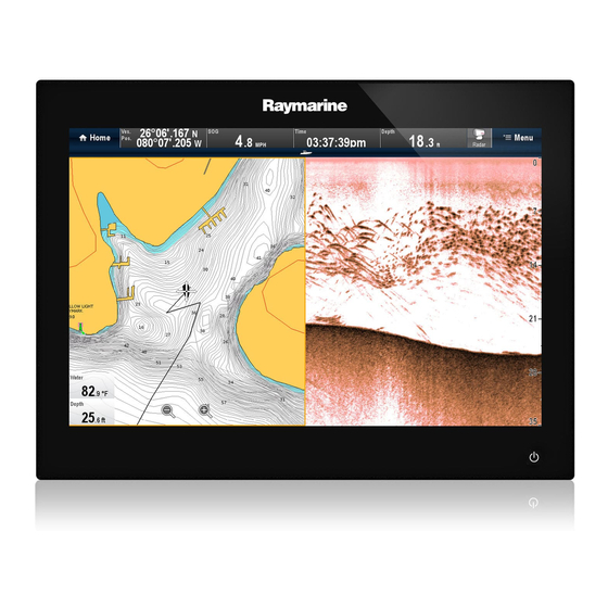
Page 13: Document Illustrations
Products may differ slightly from those shown in the Product information illustrations in this document, depending on product gS Series Multifunction Displays (MFDs) are variant and date of manufacture. touchscreen displays which have HybridTouch The illustration shown below is used throughout functionality when paired with a remote keypad. - Page 14 Series installation instructions...
-
Page 15: Chapter 3 Planning The Installation
Chapter 3: Planning the installation Chapter contents • 3.1 System integration on page 16 • 3.2 Installation checklist on page 22 • 3.3 Multiple data sources (MDS) overview on page 22 • 3.4 Identifying your display variant on page 23 •... -
Page 16: System Integration
Navionics Marine app: • Apple iPhone or iPad • Android-compatible smartphone or tablet For media player control (Touchscreen MFDs only): • Any Bluetooth-enabled device that supports Bluetooth 2.1+ EDR power class 1.5 (supported profile: AVRCP 1.0) gS Series installation instructions... - Page 17 • 1 x bait / fish. GNSS Receiver Any combination of the following: SeaTalk, SeaTalk ng® , or NMEA (external) — 0183 • RS130 GPS Raymarine ® • Raystar125 GPS • Raystar125+GPS (via optional ng® SeaTalk to SeaTalk converter) Instruments — As determined by SeaTalk ng®...
- Page 18 BNC connectors a9x / a12x / e7 / e7D source c Series = 1 e9x / e12x / e165 = 2 eS Series = 1 gS Series = 2 IP camera Multiple • CAM200IP Via SeaTalk network Note: Whilst third-party...
- Page 19 • Any 600 watt / 1Kw compatible transducer (via optional E66066 adaptor cable) ; OR: • Any Minn Kota transducer (via optional A62363 adaptor cable) Connection via external Raymarine ® Sonar Module: • Any sonar module-compatible transducer DownVision ™ Direct connection to internal...
- Page 20 Thermal camera — • T200 Series SeaTalk (for control), BNC Raymarine ® connector (for video) • T300 Series • T400 Series • T800 Series • T900 Series Remote keypad Multiple • RMK-9 SeaTalk gS Series installation instructions...
- Page 21 Fusion 700 series entertainment SeaTalk systems systems: • MS-IP700 • MS-AV700 PC / laptop Windows-compatible PC or laptop SeaTalk running Raymarine ® Voyage Planner software. Note: Raymarine ® cannot guarantee the compatibility of any third-party devices listed above. Planning the installation...
-
Page 22: Installation Checklist
NOT compliant. It may be necessary to upgrade the software for these non-compliant products to make them compliant. Visit the Raymarine website (www.raymarine.com) to obtain the latest software for your products. If MDS-compliant software is not available and you do... -
Page 23: Identifying Your Display Variant
• All networked aa Series, c Series and e Series displays must contain LightHouse software release V4.32 or later. • All networked gS Series displays must contain LightHouse software release V7.43 or later. • All networked eS Series displays must contain LightHouse software release V14.xx or later. -
Page 24: System Protocols
NMEA 0183, most notably in speed and connectivity. Up to 50 units can simultaneously transmit and receive on a single physical bus at any one time, with each node being physically addressable. The standard was specifically intended to allow for gS Series installation instructions... -
Page 25: Data Master
3.7 Data master a whole network of marine electronics from any manufacturer to communicate on a common bus via Any system containing more than one networked standardized message types and formats. multifunction display must have a designated data master. SeaTalk The data master is the display which serves as a SeaTalk is a protocol which enables compatible primary source of data for all displays, it also handles... -
Page 26: Parts Supplied
M5 Wavy washer (for additional grounding strap) 1.5 m (4.9 ft) Power / Data cable 2 m (6.6 ft) Video / Alarm cable Display mounting gasket 2 m (6.6 ft) RayNet cable Auxiliary alarm 1m (3.28 ft) SeaTalk spur cable gS Series installation instructions... -
Page 27: Tools Required For Installation
3.9 Tools required for installation 3.10 Selecting a location Warning: Potential ignition source This product is NOT approved for use in hazardous/flammable atmospheres. Do NOT install in a hazardous/flammable atmosphere (such as in an engine room or near fuel tanks). General location requirements When selecting a location for your product it is important to consider a number of factors. - Page 28 700 mm (27.5 in.) Left-hand side 250 mm (9.84 in.) D11537-2 This location provides optimal GPS performance (above decks). In this location, GPS performance may be less effective. This location is NOT recommended for GPS antenna. gS Series installation instructions...
- Page 29 LCDs can be orientated in 2 directions: For optimum EMC performance we recommend that wherever possible: • Raymarine equipment and cables connected to it are: – At least 1 m (3 ft) from any equipment transmitting or cables carrying radio signals e.g.
-
Page 30: Product Dimensions
(7.8 in) (7.8 in) (7.8 in) (7.8 in) Card reader dimensions D12725-1 55 mm (2.17 in) 55 mm (2.17 in) 8.5 mm (0.33 in) 36 mm (1.4 in) 39.2 mm (1.5 in) 90 mm (3.5 in) gS Series installation instructions... -
Page 31: Chapter 4 Cables And Connections
4.26 Fusion network connection on page 52 • 4.27 Fusion NMEA 2000 connection on page 52 • 4.28 Media player connection on page 53 • 4.29 Raymarine mobile app connection on page 53 • 4.30 Bluetooth remote control connection on page 54 Cables and connections... -
Page 32: General Cabling Guidance
Raymarine. Ensure that all data cables are properly shielded • Ensure that any non-Raymarine cables are of the that the cable shielding is intact (e.g. hasn’t been correct quality and gauge. For example, longer scraped off by being squeezed through a tight area). -
Page 33: Gs95 / Gs125 / Gs165 Connections Overview
4.2 gS95 / gS125 / gS165 Connections 4.3 gS195 connections overview overview Details of the connections available on the gS195 are shown below. Details of the connections available on the multifunction display are shown below. D13044-3 D12700-1 SeaTalk connection SeaTalk HDMI Output HDMI PoE / RayNet SeaTalk... -
Page 34: Power And Data (Combined) Connection
NOT cover every scenario. If you are unsure how to provide the correct level of protection, please consult an authorized Raymarine dealer or a suitably qualified professional marine electrician. Implementation — direct connection to battery •... - Page 35 2-wire cable from the unit to the vessel's battery or wire then it should be connected directly to the battery’s distribution panel. negative terminal. • Raymarine recommends a minimum wire gauge of 18AWG (0.82 mm ) for any length of cable Implementation — connection to distribution extension.
-
Page 36: Power Over Ethernet (Poe)
Note: A class 0 device shall be assigned the same power allocation as a class 3 device. Note: If a PoE device is connected that will take the total assigned power over 20 W the device will not be powered. gS Series installation instructions... -
Page 37: Auxiliary Alarm Connection
Chapter 12 Spares and accessories. SeaTalk power requirements The SeaTalk bus requires a 12 V power supply. Power may be provided from: • Raymarine equipment with a regulated 12 V power supply (for example, a SmartPilot SPX course computer); or: Cables and connections... -
Page 38: Nmea 2000 Connection
3. NMEA 2000 device 4. SeaTalk ng® to DeviceNet adaptor cable Connecting the display to an existing NMEA 2000 (DeviceNet) backbone D12175-3 1. MFD 2. SeaTalk ng® to DeviceNet adaptor cable 3. DeviceNet backbone 4. NMEA 2000 equipment gS Series installation instructions... -
Page 39: Seatalk Connection
4.10 SeaTalk connection 4.11 NMEA 0183 connection — Power/NMEA/Video cable You can connect SeaTalk devices to your MFD using the optional SeaTalk to SeaTalk ng® converter. NMEA 0183 devices can be connected directly to MFDs with a combined Power/NMEAVideo cable. Refer to the Connection Overview section to establish the NMEA 0183 connection method for your MFD. -
Page 40: Gigabit Networking
Data cable extension Total length (max) Cable Up to 5 m High quality data cable: • 2 x twisted pair with overall shield. • 50 to 75 pF/m capacitance core to core. gS Series installation instructions... -
Page 41: Sonar Module Connection
External sonar modules can be connected directly to Note: For software downloads and instructions the display’s network connection or can be connected on how to update the software for your product(s), to the SeaTalk network, via a Raymarine ® network visit www.raymarine.com/software. switch. -
Page 42: Radar Network Connection
2. Raymarine network switch 3. MFD 4. SeaTalk crossover coupler 4. RayNet Radar cable 5. VCM (Voltage Converter Module) — (required for Open Arrays) 6. Power connection Radar connected directly to the display D12253-3 1. Radar scanner gS Series installation instructions... - Page 43 Cable Part number variety of lengths. RayNet 5 m (16.4 ft) Power A80227 Raymarine network switch to Network cables, available in and data digital cable multifunction display. a variety of cable lengths. RayNet 10 m (32.8 ft) Power...
-
Page 44: Gnss / Gps Connection
GNSS / GPS receiver. An NMEA 0183 GNSS / GPS receiver can be connected to the MFD by following the details provided in section 4.11 NMEA 0183 connection — Power/NMEA/Video cable and the installation instructions provided with the unit. gS Series installation instructions... -
Page 45: Ais Connection
NMEA 0183. The compass is connected to the course computer and calibrated via the pilot control head; or: • A Raymarine or third-party fastheading sensor connected to the multifunction display via NMEA 0183. Note: Please contact your dealer or Raymarine technical support for more information. -
Page 46: Keypad Network Connection
For information on connecting an SR50 using D12694-3 SeaTalk please refer to 82257 – SR50 operation 1. MFD which can be downloaded from the Raymarine website: www.raymarine.com. 2. Network connection to MFD or Raymarine ® network switch (RayNet cable) For further information regarding weather receiver installation (including power connection and 3. -
Page 47: Video Connection - Composite
4.20 Video connection — composite 4.21 Camera (Video/Alarm) connection Analog cameras can be connected directly to MFDs A camera or a video device can be connected that have a composite video input connection. directly your MFD using the dedicated Video / alarm connector. -
Page 48: Hdmi Video Output
D12916-2 1. MFD D12592-5 1. MFD 2. External display (See note below) 2. CAM200IP 3. Raymarine 5 m (16.4 ft) HDMI video output cable 3. RayNet to RJ45 SeaTalk adaptor cable (A80219) 4. Ethernet coupler (R32142) Note: IP camera network connection 1. -
Page 49: Hd-Sdi Connection (Gs195)
IP camera guidance display’s Camera application. Raymarine ® MFDs are capable of displaying IP camera feeds. Whilst third-party IP cameras may work, Raymarine ® highly recommends only using Raymarine ® IP cameras such as the CAM200IP. As guidance any third-party IP camera must conform to the following: •... -
Page 50: Thermal Camera Connection
2 connections are required: • Network connection — required to control the thermal camera via a compatible Raymarine ® MFD or optional Joystick Control Unit (JCU). • Video connection — transmits the composite video signal to a compatible Raymarine ®... - Page 51 4. Raymarine ® network switch Raymarine recommends the use of a BNC terminated RG59 75ohm (or better) coaxial cable. 5. Video cable 6. RayNet to RJ45 SeaTalk adaptor cables 7. PoE (Power over Ethernet) injector (only required if using the optional JCU) 8.
-
Page 52: Fusion Network Connection
For further installation information, refer to the installation instructions supplied with the unit. Compatible Fusion units The table below details the Fusion entertainment systems that are compatible with Raymarine ® LightHouse powered MFDs. NMEA 2000... -
Page 53: Media Player Connection
The media player must be compatible with the Bluetooth 2.1+ EDR power class 1.5 (supported Raymarine apps allow you to stream and / or control, profile: AVRCP 1.0) or higher. remotely what you see on your multifunction display to a compatible device, using a Wi-Fi connection. -
Page 54: Bluetooth Remote Control Connection
4.30 Bluetooth remote control connection You can control the multifunction display wirelessly 1. Select Set-up. using a Raymarine remote control unit. 2. Select System Settings. The remote control uses a Bluetooth wireless 3. Select Wireless Connections. connection. 4. Select Bluetooth > On. -
Page 55: Remote Control Functions
Remote control functions Buttons Arrow buttons Shortcut button Range Pair Select D12051-3 Button Application where function available: Radar Weather Home- Default functions: Chart Fishfinder screen Range / zoom. • Press UP or DOWN arrow for momentary response. • Hold UP or DOWN arrow for continuous response. - Page 56 On your multifunction display, with the homescreen displayed: 1. Select Set-up. 2. Select System Settings. 3. Select External Devices. 4. Select Remote Control. 5. Select Customize shortcut key. 6. Select the function that you want to assign to the SHORTCUT key. gS Series installation instructions...
-
Page 57: Chapter 5 Mounting
Chapter 5: Mounting Chapter contents • 5.1 Bracket mounting hole locations on page 58 • 5.2 Mounting surface requirements on page 58 • 5.3 Flush mounting the display on page 59 • 5.4 Flush mounting the card reader on page 60 •... -
Page 58: Bracket Mounting Hole Locations
• If in doubt, refer to a professional marine equipment installer for further guidance. D12727-1 gS165 and gS195 bracket mounting hole locations gS125 bracket mounting hole locations gS95 bracket mounting hole locations gS Series installation instructions... -
Page 59: Flush Mounting The Display
5.3 Flush mounting the display For flush mounting you must rebate the mounting surface. D12723-2 Note: Refer to the 5.1 Bracket mounting hole locations section for details of the location of the bracket mounting holes on the rear of your display. D12706-1 11. -
Page 60: Flush Mounting The Card Reader
The gasket should be used in all installations. It may also be necessary to use a marine-grade sealant if the mounting surface or binnacle is not entirely flat and stiff or has a rough surface finish. gS Series installation instructions... -
Page 61: Surface Mounting The Display
5.5 Surface mounting the display 1. Check the selected location for the unit. A clear, flat area with suitable clearance behind the panel is required. 2. Before modifying the mounting surface, refer to the dimensions supplied in this document to ensure there is enough space for the display and all cables. -
Page 62: Surface Mounting The Card Reader
The gasket should be used in all installations. It may also be necessary to use a marine-grade sealant if the mounting surface or binnacle is not entirely flat and stiff or has a rough surface finish. gS Series installation instructions... -
Page 63: Chapter 6 Getting Started
Chapter 6: Getting started Chapter contents • 6.1 Switching the unit on and off on page 64 • 6.2 Controls on page 65 • 6.3 Basic touchscreen operations on page 66 • 6.4 Multi-Touch gestures on page 67 • 6.5 Touch icons on page 67 •... -
Page 64: Switching The Unit On And Off
Power button multiple times. head and the autopilot is engaged. Adjusting the display brightness Attention A gS Series MFD in PowerSave mode 1. Press the POWER button once. will continue to consume some power from your vessel’s batteries. The unit could drain your batteries The Shortcuts menu is displayed. -
Page 65: Controls
MicroSD card. There are 2 card slots (labelled 1 and 2), used for electronic Note: * Only applicable to gS Series displays. charts and archiving waypoint, route, track a Series, c Series and e Series displays cannot and settings data. -
Page 66: Basic Touchscreen Operations
1. Select the Set-up icon. datapages in the data application. 2. Select Touch-Lock so that Off is highlighted. 3. OK button — push the end of the joystick to The touchscreen is now unlocked. confirm a selection or entry. gS Series installation instructions... -
Page 67: Multi-Touch Gestures
6.4 Multi-Touch gestures 6.5 Touch icons Touchscreen multifunction displays can use Raymarine a Series and gS Series multifunction the BACK and CLOSE icons to move between displays support multi-touch. the different levels of menus available in each Multi-touch means that the display is capable of application. -
Page 68: Homescreen Overview - Touch Only Displays
GPS, AIS, radar, sonar and autopilot Power steering active. units. Accessing the homescreen Wind Vane mode is active. The homescreen can be accessed from any application. To access the homescreen follow the steps below: 1. Select the homescreen icon on-screen. gS Series installation instructions... - Page 69 Radar scanner status symbols Symbol Description The radar scanner power mode status is indicated AIS unit is connected and switched in the databar. on, but has active alarms. Radar power AIS unit is connected and switched Symbol mode Description on, but the dangerous and lost alarm is disabled.
-
Page 70: Pages
Save. • Choose page — The page you select will be Moving a page on the homescreen displayed after power-up With the homescreen displayed: 1. Select the Customize icon. 2. Select Homescreen. 3. Select Swap Page. gS Series installation instructions... -
Page 71: Applications
6.8 Applications 4. Select the page icon that you want to move. 5. Select the page icon that you want to swap Chart application — provides a 2D or positions with. 3D graphical view of your charts to help The page icon is moved to the new position. you navigate. -
Page 72: Splitscreen Controls
With a page featuring multiple applications displayed: 1. Press the Switch Active button. The active pane pop up is displayed: 2. Press the Switch Active Pane button or use the Rotary control to cycle the active application. gS Series installation instructions... -
Page 73: Screen Overview
6.10 Screen overview 3. Use the Range in or Range out controls to switch the active application between splitscreen and fullscreen views. Switching the active pane or display using the keypad The Switch Active button is used to switch the active pane on a multi application page and / or to switch the active display. - Page 74 On or Off. Shortcuts page Dialogs A number of useful functions can be accessed from Dialogs are fullscreen menus that enable you to the Shortcuts page. manage data items such as waypoints and routes. D12277-2 D13004-1 gS Series installation instructions...
- Page 75 4. Select the àèò key to enter the character. Decrease display brightness Increase display brightness Numeric menu items Power up / Power down Radar Numeric menu items display numeric data and enables you to either select a predefined value or to Radar standby / Radar transmit increase and decrease the value as required.
-
Page 76: Initial Set Up Procedures
As both of these factors are outside of Raymarine’s control; Screen item Description Raymarine will not be held liable for Status — provides status information for the any damage, physical or otherwise, connected equipment. For example, the Pilot resulting from the use of the automatic... - Page 77 i.e.: Minimum Safe Depth = Maximum Vessel Draft + Safety Margin. D1322-1 1. Port safety margin D13159-1 2. Maximum Vessel Width (Beam) 1. Waterline 3. Starboard safety margin 2. Maximum Vessel Draft 3. Safety Margin Important: The information below is provided for guidance only and is not exhaustive.
- Page 78 SeaTalk, NMEA and any other data connections are made, it then bridges the data to the SeaTalk network and any compatible repeat displays. Information shared by the data master includes: gS Series installation instructions...
-
Page 79: Pairing The Keypad
6.12 Pairing the keypad 6.13 Enabling autopilot control The keypad can control 1 or more multifunction Enabling the autopilot control function — displays. Multiple keypads can be connected to a SeaTalk and SPX SeaTalk autopilots system. Each keypad can be paired with up to 4 To enable control of your SeaTalk or SPX SeaTalk multifunction displays. -
Page 80: Engine Identification
• Run the Engine identification wizard to ensure that your engines are displayed in the correct order in the Data application. gS Series installation instructions... - Page 81 The wizard will now listen for data and assign For engines with a NMEA 2000 CAN bus it may the engine instance as the port engine. be possible to connect to a Raymarine MFD via a SeaTalk system without the use of a Raymarine iii.
-
Page 82: Enabling Ais Functions
• Date Format • Time Format • Local Time (UTC) offset System Preferences • Bearing mode • Variation (manual) • Language Data application • Max RPM range • RPM red zone • RPM red zone value gS Series installation instructions... -
Page 83: Memory Cards And Chart Cards
System Setup Menu. time. Chart cards provide additional or upgraded cartography. Note: Raymarine recommends that you do NOT use the simulator mode whilst navigating. It is recommended that your data is backed up to a memory card on a regular basis. Do NOT save data Note: The simulator will NOT display any real to a memory card containing cartography. -
Page 84: Memory Cards And Chart Cards
6. Use your fingers to pull the card clear of the card When archiving data or creating an electronic chart slot, using the edge of the card. card, Raymarine recommends the use of quality branded memory cards. Some brands of memory card may not work in your unit. Please contact customer support for a list of recommended cards. -
Page 85: System Software Updates
2. Compare the latest available software against the software version of your Raymarine ® products. Raymarine regularly issues software updates for 3. If the software on the website is newer than the its products that can provide new and enhanced software on your products download the relevant features and improved performance and usability. -
Page 86: Learning Resources
9. Remove the MicroSD card from the card reader. Training courses Raymarine regularly runs a range of in-depth training Note: Turning on a display whilst it has a memory courses to help you make the most of your products. -
Page 87: Chapter 7 System Checks
Chapter 7: System checks Chapter contents • 7.1 GPS Check on page 88 • 7.2 GNSS Status on page 88 • 7.3 Radar check on page 89 • 7.4 Sonar check on page 90 • 7.5 Thermal camera setup and checks on page 92 System checks... -
Page 88: Gps Check
Sky view is a visual representation that shows the position of navigation satellites and their type. Note: Raymarine recommends that you check the Satellite types are: displayed vessel position in the chart application against your actual proximity to a known charted •... -
Page 89: Radar Check
7.3 Radar check • Horizontal Dilution of Precision (HDOP) — HDOP is a measure of satellite navigation accuracy, calculated from a number of factors Warning: Radar scanner safety including satellite geometry, system errors in Before rotating the radar scanner, ensure the data transmission and system errors in the all personnel are clear. -
Page 90: Sonar Check
Description transducers. Target object (such as a buoy) dead ahead. • All variants allow the connection of a Raymarine Target displayed on the radar display is not sonar transducer via a compatible external sonar aligned with the Ship's Heading Marker (SHM). - Page 91 4. Select Speed Transducer. A list of transducers is displayed. 5. Select your speed transducer from the list. Checking the sonar Sonar checks are made using the fishfinder application. 1. Select a fishfinder page from the Homescreen. D9343--2 Waterline offset Transducer / Zero offset Keel offset If an offset is not applied, displayed depth readings...
-
Page 92: Thermal Camera Setup And Checks
In some circumstances it may be better to use just the UniControl's rotary and joystick controls to manipulate the thermal camera view. For example, this method is ideal for finer control over the camera and is particularly useful in rough sea conditions. gS Series installation instructions... -
Page 93: Chapter 8 Maintaining Your Display
Chapter 8: Maintaining your display Chapter contents • 8.1 Service and maintenance on page 94 • 8.2 Product cleaning on page 94 Maintaining your display... -
Page 94: Service And Maintenance
Best cleaning practices. components. Please refer all maintenance When cleaning products: and repair to authorized Raymarine dealers. Unauthorized repair may affect your warranty. • If your product includes a display screen, do NOT wipe the screen with a dry cloth, as this could Routine equipment checks scratch the screen coating. -
Page 95: Chapter 9 Troubleshooting
Chapter 9: Troubleshooting Chapter contents • 9.1 Troubleshooting on page 96 • 9.2 Power up troubleshooting on page 97 • 9.3 Radar troubleshooting on page 98 • 9.4 GPS troubleshooting on page 99 • 9.5 Sonar troubleshooting on page 100 •... -
Page 96: Troubleshooting
All Raymarine products are, prior to packing and shipping, subjected to comprehensive test and quality assurance programs. However, if you experience problems with the operation of your... -
Page 97: Power Up Troubleshooting
Software corruption In the unlikely event that the products software has become corrupted please try re-flashing the latest software from the Raymarine website. On display products, as a last resort, you can try to perform a ‘Power on Reset’, however this will delete all settings/presets and user data (such as waypoints and tracks) and revert the unit back to factory defaults. -
Page 98: Radar Troubleshooting
Check that the Scanner is correctly connected to a problem Raymarine network switch or SeaTalk crossover coupler (as applicable). Check the status of the Raymarine network switch. Check that SeaTalk / RayNet cables are free from damage. Software mismatch between Contact Raymarine technical support. -
Page 99: Gps Troubleshooting
9.4 GPS troubleshooting Problems with the GPS and their possible causes and solutions are described here. Problem Possible causes Possible solutions “No Fix” GPS status icon is Geographic location or prevailing Check periodically to see if a fix is obtained in better displayed. -
Page 100: Sonar Troubleshooting
/ RayNet network problem. • Check that the unit is correctly connected to the multifunction display or Raymarine network switch. If a crossover coupler or other coupler cable / adapter is used, check all connections ensuring connections are secure, clean and free from corrosion, replace if necessary. - Page 101 Possible causes Possible solutions With the product under load, using a multi-meter, check for high voltage drop across all connectors/fuses etc (this can cause the Fishfinder applications to stop scrolling or the unit to reset/turn off), replace if necessary. Vessel speed too high Slow vessel speed and recheck.
- Page 102 Possible solutions Transducer does not have a speed element Install transducer with speed element to enable speed readings. Incorrect transducer selected (no speed Select a transducer that supports speed measurement from the Transducer displayed) Set-Up menu. gS Series installation instructions...
-
Page 103: Sonar Crosstalk Interference
• Adjust the Interference Rejection Filter. The you may experience some operating in overlapping default setting for all Raymarine MFDs is “Auto”. minor crosstalk interference frequency ranges, you may Changing this setting to “High” might help to... - Page 104 Being able to easily identify the way in which interference is displayed in the Fishfinder application can sometimes be the best and easiest route to dealing with it. gS Series installation instructions...
-
Page 105: Thermal Camera Troubleshooting
VIS / IR switching. image . VIS / IR cable not connected. Ensure that the VIS / IR cable is connected from the camera to the Raymarine system. (The IR-only cable does not support switching). Noisy image. Poor quality or faulty video Ensure that the video cable is no longer than necessary. - Page 106 FFC, a small green square will appear in the upper left corner of the screen. Image is inverted (upside down). Camera “Ball down” setting is Ensure that the Ball down setting within the thermal incorrect. camera system setup menu is set correctly. gS Series installation instructions...
-
Page 107: System Data Troubleshooting
Network problem. Check that all required equipment is connected to the is missing from some but not all network. displays. Check the status of the Raymarine network Switch. Check that SeaTalk / RayNet cables are free from damage. Software mismatch between Contact Raymarine technical support. -
Page 108: Video Troubleshooting
Problems with the video inputs and their possible causes and solutions are described here. Problem Possible causes Possible solutions No signal message on screen Cable or connection fault Check that the connections are sound and free from (video image not displayed) corrosion. gS Series installation instructions... -
Page 109: Wi-Fi Troubleshooting
Ensure that the “Wi-Fi” option is enabled on the iPhone (available from the phone's Settings menu). Ensure that the Raymarine connection is selected as the Wi-Fi network. If a passcode has been specified for the multifunction display's Wi-Fi connection ensure that the same passcode is entered into the iPhone when prompted. -
Page 110: Bluetooth Troubleshooting
Multiple wireless devices running simultaneously (such signal. devices in the vicinity. as laptops, phones, and other wireless devices) can sometimes cause wireless signal conflicts. Temporarily disable each wireless device in turn until you have identified the device causing the interference. gS Series installation instructions... -
Page 111: Touchscreen Troubleshooting
9.12 Touchscreen troubleshooting Problems with the touchscreen and their possible causes and solutions are described here. Problem Possible causes Possible solutions Touchscreen does not operate Touch lock is enabled. Use the Joystick to turn off the touch lock on the home as expected. -
Page 112: Touchscreen Alignment
8. If the operation was unsuccessful at any point during the alignment exercise, an “Incorrect touch detected" message is displayed, the alignment exercise is repeated. 9. After 2 failed alignment exercises you may be asked to perform a precision alignment exercise. gS Series installation instructions... -
Page 113: Miscellaneous Troubleshooting
Check that the power source is of the correct voltage and erratic behavior. sufficient current. Software mismatch on system Go to www.raymarine.com and click on support for the (upgrade required). latest software downloads. Corrupt data / other unknown Perform a factory reset. - Page 114 Series installation instructions...
-
Page 115: Chapter 10 Technical Specification
Chapter 10: Technical specification Chapter contents • 10.1 Technical specification on page 116 Technical specification... -
Page 116: Technical Specification
• PowerSave mode: 12.4 W Operating temperature -25 ºC to +55 ºC (-13 ºF to 131 ºF) • Standby: 5 W Max Storage temperature -30 ºC to +70 ºC (-22 ºF to 158 ºF) gS Series installation instructions... - Page 117 24–bit Color depth (excluding e165) Resolution 1280 x 800 pixels 1280 x 1024 pixels e165 266.6 minutes 6 GB (WVGA) (SXGA) gS Series 14 GB 622.2 minutes Aspect Ratio 16:9 eS Series 6 GB 266.6 minutes Maximum allowable Note: wrongly •...
- Page 118 Compatible • C-MAP Essentials Jeppesen • C-MAP 4D MAX cartography • C-MAP 4D MAX+ Note: Refer to the Raymarine website (www.rayma- rine.com) for the latest list of supported charts. Conformance specification Conformance certification applies to all display variants Conformance • NMEA 2000 certification •...
-
Page 119: Chapter 11 Technical Support
Chapter 11: Technical support Chapter contents • 11.1 Raymarine customer support on page 120 • 11.2 Learning resources on page 120 • 11.3 Third-party support on page 121 Technical support... -
Page 120: Raymarine Customer Support
If you need to request service, please have the following information to hand: Training courses • Product name. Raymarine regularly runs a range of in-depth training courses to help you make the most of your products. • Product identity. Visit the Training section of the Raymarine website •... -
Page 121: Third-Party Support
11.3 Third-party support Contact and support details for third-party suppliers can be found on the appropriate websites. Fusion www.fusionelectronics.com Navionics www.navionics.com Sirius www.sirius.com Technical support... - Page 122 Series installation instructions...
-
Page 123: Chapter 12 Spares And Accessories
Chapter 12: Spares and accessories Chapter contents • 12.1 gS Series accessories on page 124 • 12.2 gS Series spares on page 124 • 12.3 Network hardware on page 125 • 12.4 Network cable connector types on page 125 •... -
Page 124: Gs Series Accessories
5 m (16.4 ft gS Series Video out A80219 gS165 suncover R70182 cable (HDMI) gS195 suncover R70290 2 m 6.6 ft) gS Series Video In / A80235 gS195 BNC (HD-SDI) protective R70292 Alarm Out cable boot kit 1.5 m (4.9 ft) Straight power and... -
Page 125: Network Hardware
— used for HS5 RayNet A80007 5–port switch for network connecting SeaTalk devices to network switch connection of multiple a Raymarine network switch via devices featuring RayNet SeaTalk cables. connectors. Equipment with RayNet connector — used for RJ45 SeaTalk... -
Page 126: Raynet To Raynet Cables And Connectors
This adapter features a RayNet (female) socket at one end, and a RayNet (male) plug at the other end. Adapter cable with a RayNet (male) Suitable for joining (female) RayNet cables together for plug on both ends. longer cable runs. gS Series installation instructions... - Page 127 • E55051 (10 m). • A62135 (15 m). • E55052 (20 m). Adapter cable with a RayNet (female) Directly connect a Raymarine radar scanner with an RJ45 socket on one end, and a waterproof SeaTalk (male) cable to a RayNet network switch (e.g.
-
Page 128: Network Cable Types
Spurs from the backbone are lengths) – Thermal camera via PoE injector. used to connect SeaTalk devices. – Additional Raymarine network switch. T-piece connector Used to make junctions in the – PC or laptop using Voyage Planner software. backbone to which devices •... -
Page 129: Seatalk Ng Cables And Accessories
12.8 SeaTalk cables and accessories Description Part No Notes SeaTalk cables and accessories for use with SeaTalk Power A06049 compatible products. cable Description Part No Notes SeaTalk A06031 Terminator SeaTalk starter kit T70134 Includes: SeaTalk T-piece A06028 Provides 1 x spur •... -
Page 130: Seatalk Accessories
3 m (9.8 ft) SeaTalk D285 extension cable 5 m (16.4 ft) D286 SeaTalk extension cable 9 m (29.5 ft) D287 SeaTalk extension cable 12 m (39.4 ft) E25051 SeaTalk extension cable 20 m (65.6 ft) D288 SeaTalk extension cable gS Series installation instructions... -
Page 131: Appendix A Connectors And Pinouts
• Video: No power required Not connected Not connected Not connected for interface. Foil Shield Isolated from 0V Power, data and video cable cores and colors Note: Use only Raymarine RayNet cables when connecting SeaTalk devices. Signal Color BATT+ SeaTalk connector BATT-... -
Page 132: Appendix B Nmea 0183 Sentences
Tracked target message ● ● Water speed and heading ● ● Distance travelled through the water ● ● Course over ground and ground speed ● ● Cross track error measured sentence ● Time and date ● ● gS Series installation instructions... -
Page 133: Appendix C Nmea Data Bridging
An example of NMEA data bridging is in a system that includes a third-party GPS receiver connected to the NMEA 0183 Input of a Raymarine display. The GPS data messages transmitted by the GPS receiver are repeated to any appropriate devices connected to the display's NMEA 2000 bus. -
Page 134: Appendix D Nmea 2000 Sentences
Time and date ● 129038 AIS Class A position report ● 129039 AIS Class B position report ● 129040 AIS Class B extended position report ● 129041 AIS Aids to Navigation (AToN) report ● ● ● 129044 Datum gS Series installation instructions... - Page 135 Bridged to Message number Message description Transmit Receive NMEA 0183 ● ● ● 129283 Cross track error ● ● ● 129284 Navigation data ● ● ● 129291 Set and drift, rapid update ● 129301 Time to or from mark ● 129539 GNSS DOPs ●...
- Page 136 EGR System Throttle Position Sensor Engine Emergency Stop Mode Warning Level 1 Warning Level 2 Power Reduction Maintenance Needed Engine Comm Error Sub or Secondary Throttle Neutral Start Protect Engine Shutting Down unknown error gS Series installation instructions...
- Page 138 www.raymarine.com...
Need help?
Do you have a question about the gs series and is the answer not in the manual?
Questions and answers