Table of Contents
Advertisement
Quick Links
Advertisement
Table of Contents

Related Manuals for ASL INTERCOM ENCHORUS ENC 1202


Summary of Contents for ASL INTERCOM ENCHORUS ENC 1202
-
Page 1: Operating Instructions
Operating Instructions ENCHORUS ENC 1202 Version 1.0... - Page 2 The contents of this document are the intellectual property of ASL Intercom BV and protected by copyright. All rights reserved for the product, the word mark and the design mark. ASL Intercom BV reserves the right to take legal action in the event of infringements.
-
Page 3: Table Of Contents
Table of Contents Table of Contents Introduction ........................5 General Considerations ....................5 1.1.1 ENC 1202 Features ....................5 About this Manual ......................6 Warranty and Copyright ....................6 Safety Precautions ......................7 General Warnings ......................7 Electric Hazards ......................... 7 Notes Regarding the Device’s Location ................ -
Page 4: Enc 1202 Version 1.0
Table of Contents Enchorus ENC 1202 Specifications ................. 49 Block Diagram ........................50 Pin Wiring .........................51 Index ..........................52 ENC 1202 Page 4 Version 1.0... -
Page 5: Introduction
General Considerations Introduction General Considerations Thank you for choosing an Enchorus ENC 1202 audio interface. The devices of the Enchorus series allow you to create a professional and flexibly scalable Dante™ network for live applications, recording studios and installations. These Dante™ format converters meet the most demanding audio requirements. They can be positioned close to the sources and destinations and do away with the need for separate DI boxes. -
Page 6: About This Manual
Introduction About this Manual About this Manual This manual is intended to get you up and running with the ENC 1202’s comprehensive feature set. It also contains important instructions for a safe use of your ENC 1202. For questions that are not answered in this document, feel free to contact your local ASL distributor or ASL directly. -
Page 7: Safety Precautions
Safety Precautions General Warnings Safety Precautions General Warnings Be sure to only use this unit in places that meet the environmental conditions. See „ “Ambient Conditions” on page 50. Never allow children to operate this device unsupervised. Children are not aware of „... -
Page 8: Notes Regarding The Device's Location
Safety Precautions Notes Regarding the Device’s Location Notes Regarding the Device’s Location WARNING Material damage due to improper handling. Do not expose the unit to temperature extremes. „ Avoid placing it in direct sunlight or near devices that radiate „ heat. Be sure to leave enough space on the sides to allow the air to „... -
Page 9: Setting Up
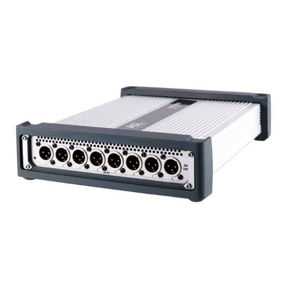
Setting Up ENC 1202 Panels Setting Up ENC 1202 Panels Front Panel 8 XLR connectors—Line Outputs 1~8 Rear Panel PRIMARY Dante port SECONDARY Dante port RJ45 port (Line In 1~4) Cooling fan. Never obstruct this area. POWER 1 connector POWER 2 connector Grounding screw ENC 1202 Page 9... -
Page 10: Connecting And Setting Up
Setting Up Connecting and Setting Up Connecting and Setting Up 3.2.1 General Considerations The ENC 1202 can be used as a desktop device, or installed in a 19” rack using one of the optional rackmount kits (see p. 44). 3.2.2 Connections Proceed as follows to connect the ENC 1202: 1. -
Page 11: The Enc 1202'S Address
Setting Up The ENC 1202’s address 5. If necessary, set the ENC 1202’s audio and network parameters. This requires the use of a computer whose Ethernet port is connected to the primary Dante network (or temporarily to the ENC 1202’s PRIMARY port). This configuration routine may only be necessary once, because the settings can be stored. - Page 12 Setting Up The ENC 1202’s address Note: • After logging in, you can open the web interface of other connected ENCHORUS-series’ devices by clicking an entry in the “NAME” column on the ENC 1202’s “Browse Network” tab (see p. 42). What if the ENC 1202’s IP Address is not displayed? If Dante Controller fails to display the IP address of a connected ENC-series device, pro- ceed as follows: 1.
-
Page 13: Application Examples
Expandable Fixed Installation and Power Amp Rack The Enchorus ENC 1202 provides a Delay function for each of the 8 line outputs, with a delay time of up to 2.7 seconds. So does the ENC 1101 (for its AES3 outputs). This can be used to correct timing differences just before the power amplifiers, without the need for an additional delay line controller, etc. - Page 14 Setting Up Application Examples For mono outputs, you can use two of the 8 internal mixers to prepare the desired mix for the left and right channels respectively. That signal could be transmitted to a second Enchorus ENC 1101 or ENC 1202 via Dante to feed additional outputs. This allows you to feed the entire power amp rack via Dante, reducing the cable count to just a single CAT-5 (or two for a redundant setup).
-
Page 15: Configuring The Unit Via Its Web Interface
Configuring the Unit via its Web Interface Operation Basics Configuring the Unit via its Web Interface This device can be configured using one of the following internet browsers: Chrome, Firefox, Internet Explorer (6.0 or newer) or Safari. Operation Basics See “The ENC 1202’s address” (p. 11) for how to access the web interface. The ENC 1202’s web interface has three sections: [1] Navigation bar The navigation bar shows the model and device names. -
Page 16: Function Bar
Configuring the Unit via its Web Interface Function Bar Function Bar 4.2.1 Left Part of the Function Bar Save Config Any changes you make to the parameters need to be saved if you want the ENC 1202 to recall them whenever it is (re)booted. All available settings of the ENC 1202 are called a “configuration”. -
Page 17: Right Part Of The Function Bar
Configuring the Unit via its Web Interface Function Bar 4.2.2 Right Part of the Function Bar Factory Reset This function allows you to restore the ENC 1202’s factory settings (also called “initializ- ing”). Careful: • Restoring the factory settings overwrites the configuration stored inside the unit. We recom- mend backing up the ENC 1202’s current configuration settings to your computer (see “Down- load Config”, p. 16) before initializing it. - Page 18 Configuring the Unit via its Web Interface Function Bar Note: • Feel free to change the password to something else using the “Password” (p. 23) parameter. If you think a password is unnecessary for your application, you can erase the current one. If you do, [Login] and [Logout] are no longer displayed.
-
Page 19: Status
Configuring the Unit via its Web Interface Status Status Click [Status] on the navigation bar to display the following page. It lists basic information about the ENC 1202. Note that none of the settings displayed here can be changed (the associated parameters are located in different panes). - Page 20 Configuring the Unit via its Web Interface Status DEVICE INFO The “Device Info” section lists basic information about the ENC 1202. Device Name Shows the device’s name. Dante Redundancy The ENC 1202’s two LAN ports can be used in Switched or Redundant mode.
- Page 21 Configuring the Unit via its Web Interface Status XML Configuration The ENC 1202 allows you to save your configuration settings as an XML file. See “Save Config” (p. 16). Some updates for the ENC 1202 also change the XML structure. All configuration files you save specify the XML version number they use.
-
Page 22: System
Configuring the Unit via its Web Interface System System Click [System] on the navigation bar to display the following page. As its name implies, this page allows you to edit system-related parameters. There are 3 sections that can be selected using the tabs below the menu bar: General, Dante Network and Updates. - Page 23 Configuring the Unit via its Web Interface System Password By default, the ENC 1202’s password is “password”. To avoid tampering by unauthorized users, we recommend specifying a different password. Be sure to write it down some- where in case you forget it. In scenarios where speed is of the essence, you may want to skip the password stage for logging into the unit.
- Page 24 Configuring the Unit via its Web Interface System DANTE SETTINGS This section is dedicated to Dante-related settings. Dante Redundancy This line indicates whether the two network adapters are used in Switched or Redundant mode. See below for how to change this setting. Redundant The ENC 1202 duplicates Dante audio traffic to both Ethernet ports, allowing the implementation of a redundant network via the SECONDARY port.
- Page 25 Configuring the Unit via its Web Interface System Dante Channels Per Flow Dante uses so-called “flows” for transmitting data to other Dante devices. By default, each flow contains 4 channels. The reason for using flows is that this makes it easier to opti- mize network traffic.
-
Page 26: System > Dante Network
Configuring the Unit via its Web Interface System 4.4.2 System > Dante Network DANTE NETWORK PRIMARY Clock State Displays the current status of the local clock. The following states may be displayed: MASTER The ENC 1202 acts as Master Clock source for the Dante network. SLAVE Another Dante device is being used as Master Clock source. - Page 27 Configuring the Unit via its Web Interface System DHCP after Reboot This is where you can select the mode the ENC 1202 will use after rebooting: After rebooting, the ENC 1202 will use a static IP address that you need to enter your- self (see below).
-
Page 28: System > Update
Configuring the Unit via its Web Interface System 4.4.3 System > Update This pane allows you to update the ENC 1202’s software and firmware. To update the software, proceed as follows: 1. Download the software update file from our website (www.asl-inter.com). 2. Click the [Select ENCHORUS update file] button at the left. A dialog window is displayed. -
Page 29: Receivers (Inputs)
Configuring the Unit via its Web Interface Receivers (Inputs) Receivers (Inputs) The “Receivers” menu allows you to view and edit all of the ENC 1202’s inputs. The drop- down menu is used to navigate the following 3 panes: General, Metering and Labels. 4.5.1 Receivers (Inputs) > General The “General”... - Page 30 Configuring the Unit via its Web Interface Receivers (Inputs) Full Scale Reference This fader icon allows you to set the analog reference level for 0dBFS (digital full-scale level, i.e. the highest digital level before clipping occurs). Depending on the console(s) used and on the requirements of the organization or client one is working for, this refer- ence may have to be +15dBu= 0dBFS, +24dBu= 0dBFS, or something else.
- Page 31 Configuring the Unit via its Web Interface Receivers (Inputs) 2. The cutoff frequency (Freq) can be set with the knob icon: click it and hold down the mouse button to select the desired frequency (20Hz~20kHz). You can also set the frequency by clicking and dragging the gray area in the curve section.
-
Page 32: Receivers (Inputs) > Metering
Configuring the Unit via its Web Interface Receivers (Inputs) 4.5.2 Receivers (Inputs) > Metering This is where the current peak levels are displayed for all of the ENC 1202’s inputs. Use the tabs to switch between the “Dante 1–8” and “Line 1–4” groups. The tabs allow you to view the levels (–126dBFS~0dBFS) of the corresponding input chan- nels. - Page 33 Configuring the Unit via its Web Interface Receivers (Inputs) Label The text field displays the channel’s current name. To edit a label, click the field, enter the desired name and press the ENTER key on the computer keyboard. ENC 1202 Page 33 Version 1.0...
-
Page 34: Transmitters (Outputs)
Configuring the Unit via its Web Interface Transmitters (Outputs) Transmitters (Outputs) The “Transmitters” menu structure is very similar to that of the “Receivers” menu. This is where you can view and edit the ENC 1202’s outputs. The dropdown menu provides access to three sections: General, Metering and Labels. 4.6.1 Transmitters (Outputs) > General This pane allows you to edit basic settings for the outputs. -
Page 35: Transmitters (Outputs) > Metering
Configuring the Unit via its Web Interface Transmitters (Outputs) Double-click the fader to set it to the minimum value. Hold down the Shift key while dou- ble-clicking the fader to reset the fader to the default value. Note: • In Transparent mode, “Trim” and “Delay” are not displayed, because these functions are bypassed. -
Page 36: Transmitters (Outputs) > Labels
Configuring the Unit via its Web Interface Transmitters (Outputs) 4.6.3 Transmitters (Outputs) > Labels By default, all output channels have names based on their types, like “01 DANTE TX” for the first Dante output. This pane allows you to assign more meaningful names. The channels are grouped by type and displayed on separate tabs. Be sure to check whether you have selected the correct tab before changing any labels. -
Page 37: Routing
Configuring the Unit via its Web Interface Routing Routing The “Routing” menu allows you to view and edit the ENC 1202’s channel assignments. 4.7.1 Routing > Dante The “Dante” submenu is used to change the routing settings within the Dante network. This is where you can establish the desired connections (Subscriptions) in the virtual Dante matrix. - Page 38 Configuring the Unit via its Web Interface Routing Establishing and Clearing a Subscription Establishing or Changing a Connection To establish a subscription or change an existing one, proceed as follows: 1. Click the right plug symbol ( A dialog appears where you can add/edit a subscription. All Dante devices discovered on the network are displayed. 2.
- Page 39 Configuring the Unit via its Web Interface Routing Status Shows the connection status: NONE This input on the ENC 1202 is not connected to any Dante output. No subscription available. DYNAMIC This input is connected and in use. “Dynamic” is the default setting for point-to-point subscriptions.
-
Page 40: Routing > I/O
Configuring the Unit via its Web Interface Routing 4.7.2 Routing > I/O The “I/O” submenu is used to change the routing settings of the ENC 1202. The settings are displayed and can be edited on the “Dante 1~8”, “Line” and “Mixer” tabs. The structure is more or less the same for all tabs: each has 3 columns. -
Page 41: Mixer
Configuring the Unit via its Web Interface Mixer Mixer The “Mixer” pane is where you can edit the mixer settings. The ENC 1202 provides 8 stereo mixers. Their settings are displayed and can be edited on the “Mix 1”~“Mix 8” tabs. All tabs use the same structure and provide the same functions. Parameters of the Selected Mixer Mute Allows you to mute (ON, orange) or activate (OFF) the selected mixer (Mixer 1 in our... -
Page 42: Browse Network
Configuring the Unit via its Web Interface Browse Network LEVEL The source level can be changed in steps of 0.5dB using the fader. The setting range is –91dB~24dB. The signal level can be lowered or boosted. The value field to the right of the fader allows you to enter more precise values (in steps of 0.1dB). -
Page 43: Error Messages
Configuring the Unit via its Web Interface Error Messages 4.10 Error Messages The following error messages may be displayed: Invalid Firmware version detected You need to install a new ENCHORUS firmware version. See “Update” (p. 28). Software Update Failed! The software could not be updated. Please try again. If that doesn’t work, download the update file again. -
Page 44: Appendix
Appendix Optional 19” Rackmount Kit for One Device (RM ENC 1202) Appendix Optional 19” Rackmount Kit for One Device (RM ENC 1202) An optional 19” rackmount kit is available for the ENC 1202. It offers the added convenience of providing separate XLR sockets for the four XLR line inputs (assigned to an RJ45 socket on the unit itself). -
Page 45: Optional 19" Rackmount Kit For Two Enchorus Devices (Rm Enc Dual)
Appendix Optional 19” Rackmount Kit for Two ENCHORUS Devices (RM ENC DUAL) 3. Remove the rubber bumper from the ENCHORUS’s front panel. 4. Using two cylinder-head screws, attach the long front blind (3) to the right edge of the ENC 1202’s front panel. 5. - Page 46 Appendix Optional 19” Rackmount Kit for Two ENCHORUS Devices (RM ENC DUAL) 3. Using two cylinder-head screws, attach the front connecting blind to the right edge of the ENCHORUS’s front panel. 4. Using two cylinder-head screws, attach the left front blind to the left edge of the ENCHORUS’s front panel.
- Page 47 Appendix Optional 19” Rackmount Kit for Two ENCHORUS Devices (RM ENC DUAL) 7. Retighten the two cylinder-head screws on the left side of the ENCHORUS’s rear panel. 8. Using two cylinder-head screws, secure the connecting blind affixed to the rear panel of the first ENCHORUS to the right side of the second ENCHORUS’s rear panel.
-
Page 48: Eu Declaration Of Conformity
Appendix EU Declaration of Conformity ??? EU Declaration of Conformity ??? Amerikanische Declaration of Conformity??? ENC 1202 Page 48 Version 1.0... -
Page 49: Enchorus Enc 1202 Specifications
Enchorus ENC 1202 Specifications Enchorus ENC 1202 Specifications Dimensions Width [mm] Length [mm] Height [mm] Weight [kg] ±1.7 Electrical Specifications Supply voltage 100~240 V AC Dante Sample rate 44,1 kHz / 48,0 kHz / 88,2 kHz / 96 kHz / 176,4 kHz / 192 kHz Word length (sample depth) -
Page 50: Block Diagram
Enchorus ENC 1202 Specifications Block Diagram Frequency response (0dBu, Fs=96kHz) @15dBu: 20Hz~40kHz (+0.0dB, –0.18dB) @24dBu: 20Hz~40kHz (+0.0dB, –0.2dB) Signal-to-noise ratio (A-weighted) @15dBu: >115dB @24dBu: > 120dB THD+N (–1dBFS 1kHz Sine, @15dBu: < –97dB (<0.0014%) BW= 20Hz~20kHz) @24dBu: < –100dB (<0.001%) Crosstalk (output to input leakage) @15dBu: >... -
Page 51: Pin Wiring
Enchorus ENC 1202 Specifications Pin Wiring Pin Wiring EtherCon (RJ45) Pin Wiring ENC 1202 Page 51 Version 1.0... -
Page 52: Index
Index Index Accessories, 49 Gain, 31 Rackmount, 44 AES67 Gateway, 27 Reboot, 17 Multicast prefix, 25 Grounding screw, 9 Receivers, 29 Settings, 25 Redundancy, 20 Support, 25 Redundant, 24 Ambient conditions, 49 High-shelf, 31 Restore Config, 16 Application example, 13 Routing, 37 Rx util, 26 I/O, 40... - Page 53 ASL Intercom B.V. Zonnebaan 42 3542 EG Utrecht Netherlands E-Mail: info@asl-inter.com www.asl-inter.com...
Need help?
Do you have a question about the ENCHORUS ENC 1202 and is the answer not in the manual?
Questions and answers