
Related Manuals for Contec GCOM-2C2-PCI


Summary of Contents for Contec GCOM-2C2-PCI
- Page 1 PC-HELPER RS-232C Serial I/O Board for PCI 2-ch GCOM-2C2-PCI 4-ch GCOM-4C2-PCI 8-ch GCOM-8C2-PCI User’s Guide CONTEC CO.,LTD.
- Page 2 Check Your Package Thank you for purchasing the CONTEC product. The product consists of the items listed below. Check, with the following list, that your package is complete. If you discover damaged or missing items, contact your retailer. Product Configuration List...
-
Page 3: Trademarks
No part of this document may be copied or reproduced in any form by any means without prior written consent of CONTEC Co., LTD. CONTEC Co., LTD. makes no commitment to update or keep current the information contained in this document. The information in this document is subject to change without notice. -
Page 4: Table Of Contents
The check method of the completion of hardware installation ..........17 Step 3 Initializing the Software ......................18 For use under Windows XP, Windows 2000 ................18 Step 4 Checking Operations with the Diagnosis Program ............... 19 GCOM-2C2-PCI, GCOM-4C2-PCI, GCOM-8C2-PCI... - Page 5 Setup Troubleshooting........................22 If you have some problem ......................22 EXTERNAL CONNECTION In the case of GCOM-2C2-PCI ......................24 Connecting directly to the port connector ................. 24 In the case of GCOM-4C2-PCI ......................25 Converting the Interface Connector to 9-pin D-SUB, Male Connectors ......... 25 Converting the Interface Connector to 25-pin D-SUB, Male Connectors .......
-
Page 6: Before Using The Product
This board is a PCI bus interface board for performing RS-232C serial communications with external devices. The <GCOM-2C2-PCI> has two serial ports per board. The <GCOM-4C2-PCI> has four serial ports per board. The <GCOM-8C2-PCI> has eight serial ports per board. -
Page 7: Support Software
Standard COM Driver Software DRV-COM(WDM) The purpose of this software is to allow the CONTEC serial communication boards to be used under Windows in the same way as the standard COM ports on the PC. By installing additional boards, you can use COM ports in the range COM1 - COM256. -
Page 8: Cable & Connector (Option)
Set of five 78-pin D-SUB (male) connectors CN5-D78M Accessories (Option) Connection Conversion Unit for RS-232C(78P→25P x 8) CCU-78F/25M *1 *1 The option cable RSS-78M or RSS-78M/37M is needed. Check the CONTEC’s Web site for more information on these options. GCOM-2C2-PCI, GCOM-4C2-PCI, GCOM-8C2-PCI... -
Page 9: Customer Support
You can download updated driver software and differential files as well as sample programs available in several languages. Note! For product information Contact your retailer if you have any technical question about a CONTEC product or need its price, delivery time, or estimate information. Limited Three-Years Warranty CONTEC Interface boards are warranted by CONTEC Co., LTD. -
Page 10: Safety Precautions
WARNING indicates a potentially hazardous situation which, if not avoided, could WARNING result in death or serious injury. CAUTION indicates a potentially hazardous situation which, if not avoided, may CAUTION result in minor or moderate injury or in property damage. GCOM-2C2-PCI, GCOM-4C2-PCI, GCOM-8C2-PCI... -
Page 11: Handling Precautions
Even when using the product continuously, be sure to read the manual and understand the contents. Do not modify the product. CONTEC will bear no responsibility for any problems, etc., resulting from modifying this product. Regardless of the foregoing statements, CONTEC is not liable for any damages whatsoever (including damages for loss of business profits) arising out of the use or inability to use this CONTEC product or the information contained herein. -
Page 12: Environment
(3) Store the package at room temperature at a place free from direct sunlight, moisture, shock, vibration, magnetism, and static electricity. Disposal When disposing of the product, follow the disposal procedures stipulated under the relevant laws and municipal ordinances. GCOM-2C2-PCI, GCOM-4C2-PCI, GCOM-8C2-PCI... - Page 13 1. Before Using the Product GCOM-2C2-PCI, GCOM-4C2-PCI, GCOM-8C2-PCI...
-
Page 14: Setup
Step 4 Checking Operations with the Diagnosis Program On the CD-ROM, refer to the installation instructions files for each OS located in the \DRVCOM\Pci\InstDoc If Setup fails to be performed normally, see the “Setup Troubleshooting” section at the end of this chapter. GCOM-2C2-PCI, GCOM-4C2-PCI, GCOM-8C2-PCI... -
Page 15: Step 1 Setting The Hardware
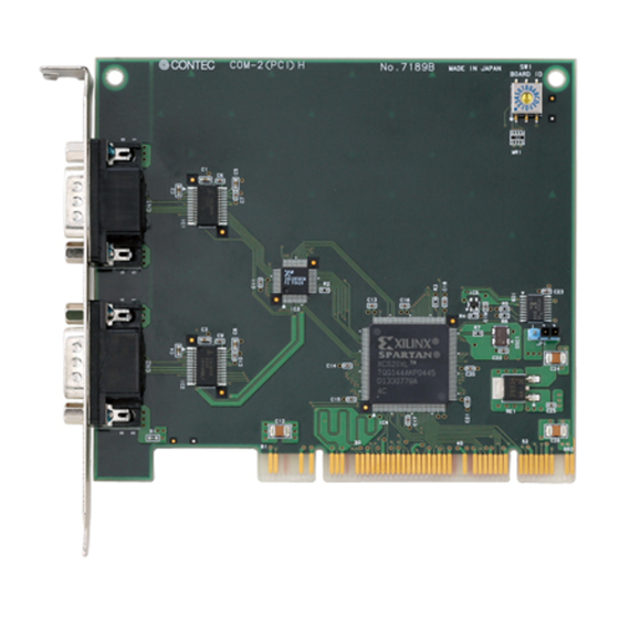
Note that the switch setting shown below is the factory default. GCOM-2C2-PCI - Interface connector GCOM-2C2-PCI COM-2(PCI)H (CN1, CN2) - BOARD ID Setting Switch BOARD ID (SW1) BOARD ID - PCI bus slot power voltage setting jumper 1 2 3 Figure 2.1. Component Locations < GCOM-2C2-PCI > GCOM-2C2-PCI, GCOM-4C2-PCI, GCOM-8C2-PCI... - Page 16 Figure 2.2. Component Locations < GCOM-4C2-PCI > GCOM-8C2-PCI - Interface connector COM-8(PCI)H GCOM-8C2-PCI - BOARD ID Setting Switch (CN1) BOARD ID (SW1) BOARD ID - PCI bus slot power voltage setting jumper 1 2 3 Figure 2.3. Component Locations < GCOM-8C2-PCI > GCOM-2C2-PCI, GCOM-4C2-PCI, GCOM-8C2-PCI...
-
Page 17: Setting The Board Id
When 5 V power is supplied, set the JP1 to the 2-3 connected state (factory default). If 5 V power is not supplied, set the JP1 to the 1-2 connected state. If outputting 5V power supply If not outputting 5V power supply 1 2 3 1 2 3 (Factory setting) (Factory setting) Figure 2.5. Setting the Supply Voltage GCOM-2C2-PCI, GCOM-4C2-PCI, GCOM-8C2-PCI... -
Page 18: Plugging The Board
Doing so could cause trouble. Be sure that the personal computer or the I/O expansion unit power is turned off. Make sure that your PC or expansion unit can supply ample power to all the boards installed. Insufficiently energized boards could malfunction, overheat, or cause a failure. GCOM-2C2-PCI, GCOM-4C2-PCI, GCOM-8C2-PCI... -
Page 19: Step 2 Installing The Hardware
If you remove two or more boards that have already been installed and then remount one of them on the computer, it is unknown that which one of the sets of resources previously assigned to the two boards is assigned to the remounted board. In this case, you must check the resource settings. GCOM-2C2-PCI, GCOM-4C2-PCI, GCOM-8C2-PCI... -
Page 20: Setting With The Add New Hardware Wizard
(1) The “Add New Hardware Wizard” will be started. Select “Install from a list or specific location”, then click on the [Next] button. (2) Specify that folder on the CD-ROM which contains the setup information (INF) file to register the board. Source folder \INF\WDM\Com DRVCOM\Pci\ComDrv GCOM-2C2-PCI, GCOM-4C2-PCI, GCOM-8C2-PCI... - Page 21 (3) Installation of the "Communication Port" starts next. If prompted for a file by the OS, specify the location of the setup information (INF) file, as described above. * The name of the board you have just added is displayed. - GCOM-2C2-PCI - GCOM-4C2-PCI - GCOM-8C2-PCI You have now finished installing the hardware. GCOM-2C2-PCI, GCOM-4C2-PCI, GCOM-8C2-PCI...
-
Page 22: The Check Method Of The Completion Of Hardware Installation
(1) Select "System" from "Control Panel" and open [Device Manager]. (2) Check that the names of the boards you are using are registered correctly in the [Multifunction adapters] folder. (3) Similarly, confirm that the COM ports have been added in the [Ports] folder. GCOM-2C2-PCI, GCOM-4C2-PCI, GCOM-8C2-PCI... -
Page 23: Step 3 Initializing The Software
(1) If you wish to change a port number, open the properties page for the port and click the [Advanced…] button under [Port Settings]. (2) Use the [COM Port Number] combo box to modify the COM port number. You have now finished installing the initial setting of Software. GCOM-2C2-PCI, GCOM-4C2-PCI, GCOM-8C2-PCI... -
Page 24: Step 4 Checking Operations With The Diagnosis Program
Obtain an RS-232C cross cable or a loopback connector. If using a loopback connector, you can test a single COM port on its own. The diagram below shows the connections for a loopback connector. Wiring diagram for loopback connector <9-pin> <25-pin> Board side Board side GCOM-2C2-PCI, GCOM-4C2-PCI, GCOM-8C2-PCI... -
Page 25: Using The Diagnosis Program
If connecting two COM ports via a cross cable, specify the respective COM ports in [Device1] and [Device2]. If using a loopback connector, specify the same port number in both [Device1] and [Device2]. Communication Settings: Specify the [Bits / Second], [Data bits] and other settings you wish to use. GCOM-2C2-PCI, GCOM-4C2-PCI, GCOM-8C2-PCI... - Page 26 2. Setup Start test Click the [Start] button to start the test using the specified conditions. View test result The test result is displayed in the [Message] window. A successful completion message appears if the test completed OK. GCOM-2C2-PCI, GCOM-4C2-PCI, GCOM-8C2-PCI...
-
Page 27: Setup Troubleshooting
2. Setup Setup Troubleshooting If you have some problem Contact your retailer. GCOM-2C2-PCI, GCOM-4C2-PCI, GCOM-8C2-PCI... -
Page 28: External Connection
In addition to connecting directly to the connector on the board, you can also connect external devices via a connection conversion cable or connection con. version unit. Connecting directly to the port connector. Using a connection conversion cable (GCOM-4C2-PCI, GCOM-8C2-PCI) Using a connection conversion unit (GCOM-4C2-PCI, GCOM-8C2-PCI) GCOM-2C2-PCI, GCOM-4C2-PCI, GCOM-8C2-PCI... -
Page 29: In The Case Of Gcom-2C2-Pci
TxD2 Transmit Data Clear to Send CTS2 DTR2 Data Terminal Ready Ring Indicator Signal Ground Figure 3.2. Pin Assignments of Interface Connector < GCOM-2C2-PCI > Cable (Option) RS-232C Straight Cable with D-SUB9P (1.8m) RSS-9M/F RS-232C Cross Cable with D-SUB9P (1.8m) -
Page 30: In The Case Of Gcom-4C2-Pci
17JE-13090-02(D8C) (mfd. by DDK, Female) Figure 3.3. Specification of “PCE37/9PS” Connection conversion cable (Option) Connection Conversion Cable (37M→9M x 4, 250mm) PCE37/9PS Cable (Option) RS-232C Straight Cable with D-SUB9P (1.8m) RSS-9M/F RS-232C Cross Cable with D-SUB9P (1.8m) RSC-9F GCOM-2C2-PCI, GCOM-4C2-PCI, GCOM-8C2-PCI... -
Page 31: Converting The Interface Connector To 25-Pin D-Sub, Male Connectors
RS-232C Straight Cable with D-SUB25P (1.8m) RSS-25M/F RS-232C Cross Cable with D-SUB25P (1.8m) RSC-25F RS-232C Connection Conversion Straight Cable (25M→9F, 1.8m) RSS-25M/9F RS-232C Connection Conversion Straight Cable (25F→9M, 1.8m) RSS-25F/9M RS-232C Connection Conversion Cross Cable (25F→9F, 1.8m) RSC-25F/9F GCOM-2C2-PCI, GCOM-4C2-PCI, GCOM-8C2-PCI... -
Page 32: When Using The Ccu-78F/25M Connection Conversion Unit
Power supply output * Thumb screw: UNC#4-40(inch screrw) N.C. - Applicable 17JE-13250-02(D8C)(mfd. by DDK, Female) * A power supply output is referred to. CN5-D25F (mfd. by CONTEC, Female) (Five connector set) Figure 3.6. Pin Assignments of Interface Connector GCOM-2C2-PCI, GCOM-4C2-PCI, GCOM-8C2-PCI... -
Page 33: Connecting Directly To The Port Connector
- Applicable connector 17JE-23370-02(D8C) (mfd. by DDK, Male) FDCD-37P (mfd. by HIROSE, Male) DC-37P-N (mfd. by JAE, Male) CN5-D37M (mfd. by CONTEC, Male) (Five connector set) Figure 3.7. Interface Connector < GCOM-4C2-PCI > TxD1 CH1 Transmit Data 1 CH1 Receive Data 1... -
Page 34: In The Case Of Gcom-8C2-Pci
(mfd. by DDK, Female) Figure 3.9. Specification of “PCE78/9PS” Connection conversion cable (Option) Connection Conversion Cable (78P→25P x 8) PCE78/9PS Connection cable (Option) RS-232C Straight Cable with D-SUB9P (1.8m) RSS-9M/F RS-232C Cross Cable with D-SUB9P (1.8m) RSC-9F GCOM-2C2-PCI, GCOM-4C2-PCI, GCOM-8C2-PCI... -
Page 35: Converting The Interface Connector To 25-Pin D-Sub, Male Connectors
RS-232C Straight Cable with D-SUB25P (1.8m) RSS-25M/F RS-232C Cross Cable with D-SUB25P (1.8m) RSC-25F RS-232C Connection Conversion Straight Cable (25M→9F, 1.8m) RSS-25M/9F RS-232C Connection Conversion Straight Cable (25F→9M, 1.8m) RSS-25F/9M RS-232C Connection Conversion Cross Cable (25F→9F, 1.8m) RSC-25F/9F GCOM-2C2-PCI, GCOM-4C2-PCI, GCOM-8C2-PCI... -
Page 36: When Using The Ccu-78F/25M Connection Conversion Unit
Power supply output * Thumb screw: UNC#4-40(inch screrw) N.C. - Applicable 17JE-13250-02(D8C)(mfd. by DDK, Female) * A power supply output is referred to. CN5-D25F (mfd. by CONTEC, Female) (Five connector set) Figure 3.12. Pin Assignments of Interface Connector GCOM-2C2-PCI, GCOM-4C2-PCI, GCOM-8C2-PCI... -
Page 37: Connecting Directly To The Port Connector
Pin Assignment Screw nut: UNC#4-40(inch screw) - Connector used 78-pin D-SUB, female connector DV11603G4 (mfd. by FOXCONN)equivalent - Applicable connector CN5-D78M (mfd. by CONTEC, Male) (Five connector set) Figure 3.13. Interface Connector < GCOM-8C2-PCI > GCOM-2C2-PCI, GCOM-4C2-PCI, GCOM-8C2-PCI... - Page 38 1.5mm (typically about 1.0mm), simply tighten the adjusting screw located on the side of the connector to install it properly. The connector should function without a problem. Figure 3.15. The note about external connection < GCOM-8C2-PCI > GCOM-2C2-PCI, GCOM-4C2-PCI, GCOM-8C2-PCI...
-
Page 39: Types Of Cable And Example Connections
(Data Terminal Ready) (Data Set Ready) (Signal Ground) External device Figure 3.16. Example Connection to a Modem (Straight cable) External device Figure 3.17. Example Connection to a PC (Cross cable) External device Figure 3.18. Example Connection to a Device GCOM-2C2-PCI, GCOM-4C2-PCI, GCOM-8C2-PCI... -
Page 40: Functions
Alternatively, setting a small FIFO trigger size or disabling FIFO operation increases the speed of data sending and receiving but increases the load on the CPU and risks received data being missed. As the FIFO buffer size is variable, you can adjust this setting to achieve optimum performance for your system. GCOM-2C2-PCI, GCOM-4C2-PCI, GCOM-8C2-PCI... -
Page 41: Setting The Baud Rate
115200 ÷ Desired baud rate = Division register setting value Ex.) 115200 ÷ 9600bps = 12 (As the result is an integer, this baud rate can be set.) 115200 ÷ 76800bps = 1.5 (As the result contains a fractional part, this baud rate cannot be set.) GCOM-2C2-PCI, GCOM-4C2-PCI, GCOM-8C2-PCI... - Page 42 134.5 0.058 1713 0.0006 3426 0.0006 6852 0.0006 1536 3072 6144 1536 3072 1536 1200 1800 2000 0.68 0.17 0.17 0.04 2400 3600 4800 7200 9600 14400 19200 28800 38400 57600 76800 115200 153600 230400 460800 921600 GCOM-2C2-PCI, GCOM-4C2-PCI, GCOM-8C2-PCI...
- Page 43 4. Functions GCOM-2C2-PCI, GCOM-4C2-PCI, GCOM-8C2-PCI...
-
Page 44: About Software
Source folder: DRVCOM\Samples\Vb Visual C++ sample programs (1) Transmit sample Sends data entered from the keyboard. Execute from the command prompt. Source folder: DRVCOM\Samples\Vc\Comsend.c file (2) Receive sample Displays received data on the screen. Source folder: DRVCOM\Samples\Vc\Comread.c file GCOM-2C2-PCI, GCOM-4C2-PCI, GCOM-8C2-PCI... -
Page 45: Uninstalling The Driver Software
(2) Expand [Multifunction adapters] and delete [CONTEC Co., Ltd-XXXXXXXXXX] (installed hardware name). (3) Start [Add/Remove Programs] from the Control Panel. (4) Select [CONTEC DRV-COM driver] from the list of applications, then click the [Add/Remove] button to automatically start the uninstall procedure. GCOM-2C2-PCI, GCOM-4C2-PCI, GCOM-8C2-PCI... -
Page 46: Cd-Rom Directory Structure
5. About Software CD-ROM Directory Structure GCOM-2C2-PCI, GCOM-4C2-PCI, GCOM-8C2-PCI... - Page 47 5. About Software GCOM-2C2-PCI, GCOM-4C2-PCI, GCOM-8C2-PCI...
-
Page 48: About Hardware
The interrupt signals from individual channels are arranged into a single interrupt signal and connected to the PCI bus. Boards with different board numbers are different in these specifications. See Table 6.4 "Different in the specification" at the end of this document. GCOM-2C2-PCI, GCOM-4C2-PCI, GCOM-8C2-PCI... - Page 49 The interrupt signals from individual channels are arranged into a single interrupt signal and connected to the PCI bus. Boards with different board numbers are different in these specifications. See Table 6.4 "Different in the specification" at the end of this document. GCOM-2C2-PCI, GCOM-4C2-PCI, GCOM-8C2-PCI...
- Page 50 The interrupt signals from individual channels are arranged into a single interrupt signal and connected to the PCI bus. Boards with different board numbers are different in these specifications. See Table 6.4 "Different in the specification" at the end of this document. GCOM-2C2-PCI, GCOM-4C2-PCI, GCOM-8C2-PCI...
- Page 51 6. About Hardware Board Dimensions [GCOM-2C2-PCI, GCOM-4C2-PCI, GCOM-8C2-PCI] 121.69(L) [mm] The standard outside dimension (L) is the distance from the end of the board to the outer surface of the slot cover. The Board No. is described above the board.
- Page 52 6. About Hardware GCOM-2C2-PCI, GCOM-4C2-PCI, GCOM-8C2-PCI...
- Page 53 3-9-31, Himesato, Nishiyodogawa-ku, Osaka 555-0025, Japan Japanese http://www.contec.co.jp/ English http://www.contec.com/ Chinese http://www.contec.com.cn/ No part of this document may be copied or reproduced in any form by any means without prior written consent of CONTEC CO., LTD. [08102006] [0710006] Management No. A-51-215 [0710006_rev1] Parts No.
Need help?
Do you have a question about the GCOM-2C2-PCI and is the answer not in the manual?
Questions and answers