Table of Contents
Advertisement
Quick Links
Reference Manual
Industrial Mainboard
GMB-IH61000
CONTENTS
Introduction .................................................................. 4
Safety Precautions .................................................... 10
Product Nomenclature and Function ............... 16
BIOS Setup .................................................................. 35
Appendix ...................................................................... 64
List of Optional Products ....................................... 75
Customer Support and Inquiry ............................ 77
Advertisement
Table of Contents

Subscribe to Our Youtube Channel
Related Manuals for Contec GMB-IH61000


Summary of Contents for Contec GMB-IH61000
- Page 1 Reference Manual Industrial Mainboard GMB-IH61000 CONTENTS Introduction ..............4 Safety Precautions ............ 10 Product Nomenclature and Function ....16 BIOS Setup ..............35 Appendix ..............64 List of Optional Products ........75 Customer Support and Inquiry ......77...
-
Page 2: Table Of Contents
Table of Contents Introduction ..............4 1. Related Manuals ..............................5 2. About the Product ..............................6 3. Features ..................................7 4. Supported OS ................................8 5. Product Configuration List ..........................9 Safety Precautions ............10 1. Safety Information ............................... 11 2. Handling Precautions ............................12 1. - Page 3 Table of Contents BIOS Setup ..............35 1. Introduction ................................36 1. Starting Setup ..............................36 2. Using Setup ..............................37 3. Getting Help ..............................37 4. In Case of Problems ............................. 37 5. A Final Note About Setup .......................... 37 2.
-
Page 4: Introduction
Introduction This section provides necessary information of the product such as the outline, bundled items and manuals before actual use. - 4 -... -
Page 5: Related Manuals
— — Introduction GMB-IH61000 Reference Manual 1. Related Manuals The manuals related to the product are listed below. Read them as necessary along with this document. ◆ Must Read the Following Manuals Name Purpose Contents How to get Read this when operating... -
Page 6: About The Product
/ 13 Gen Core™ Processors CPU in LGA1700 socket technology with energy efficient architecture. GMB-IH61000 adopts two DDR5 SO-DIMM sockets and supports up to 64GB memory. The low-profile SKU solutions are suitable for factory automation applications. Moreover, with the high performance and high-end specifications and build-in TPM for security application, GMB-IH61000 is our first New platform architecture on Mini-ITX product line. -
Page 7: Features
— — Introduction GMB-IH61000 Reference Manual 3. Features ◼ Intel ® / 13 Alder Lake-S / Raptor Lake-S Platform This product is equipped with the 12 / 13 generation Intel Core™, Celeron & Pentium processors. ® ® ® Adopting embedded-type CPU contributes to a stable supply. -
Page 8: Supported Os
— — Introduction GMB-IH61000 Reference Manual 4. Supported OS ® Windows 10 IoT Enterprise LTSC 2021 (64 bit) - 8 -... -
Page 9: Product Configuration List
Product Guide Screw for fixing M.2 Module (M3x6 NI) *1 The configuration and parts of this product are shown below. *2 The user manual for this product is available as a PDF file through CONTEC’s website. Production Configuration Drawings Product Guide... -
Page 10: Safety Precautions
Safety Precautions Understand the following definitions and precautions to use the product safely. Never fail to read them before using the product. - 10 -... -
Page 11: Safety Information
— — Safety Precautions GMB-IH61000 Reference Manual 1. Safety Information This document provides safety information using the following symbols to prevent accidents resulting in injury or death and the destruction of equipment and resources. Understand the meanings of these labels to operate the equipment safely. -
Page 12: Handling Precautions
— — Safety Precautions GMB-IH61000 Reference Manual 2. Handling Precautions WARNING Always check that the power supply is turned off before connecting or disconnecting power ⚫ cables. Do not modify the product. ⚫ Always turn off the power before inserting or removing circuit boards or cables. - Page 13 To prevent corruption of files, always shutdown the OS before turning off this product. ⚫ CONTEC reserves the right to refuse to service a product modified by the user. ⚫ In the event of failure or abnormality (foul smells or excessive heat generation), unplug the ⚫...
-
Page 14: Fcc Part 15 Class B Notice
— — Safety Precautions GMB-IH61000 Reference Manual 1. FCC PART 15 Class B Notice NOTE This equipment has been tested and found to comply with the limits for a Class B digital device, pursuant to part 15 of the FCC Rules. These limits are designed to provide reasonable protection against harmful interference when the equipment is operated in a commercial environment. -
Page 15: Security Warning
— — Safety Precautions GMB-IH61000 Reference Manual 3. Security Warning When connecting to the network, be aware of security-related problems. See the examples of Security measures below and set up the product properly along with the network devices. 1. Information security risks Unauthorized access from the outside through a network could cause the system halt, data ⚫... -
Page 16: Product Nomenclature And Function
Product Nomenclature and Function This section describes product component names and their functions, pin assignment of each connector. - 16 -... -
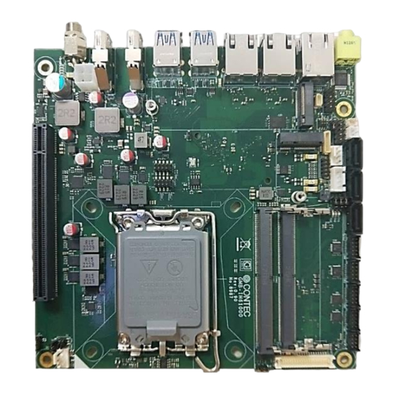
Page 17: Product Overview
— — Product Nomenclature and Function GMB-IH61000 Reference Manual 1. Product Overview connectors of the product are shown in the picture below. ◆ Top View - 17 -... - Page 18 — — Product Nomenclature and Function GMB-IH61000 Reference Manual Ref. Connector Function POW1 DC-IN Jack / (SMK:DCD-020-105J3B) Display Port Connector (Upright Type) Display Port Connector (Upright Type) USB2 USB 3.2 Gen1 Connector (Dual Type A Stack) USB1 USB 3.2 Gen1 Connector (Dual Type A Stack) LANC RJ45 Connector 2.5GbE Port...
- Page 19 — — Product Nomenclature and Function GMB-IH61000 Reference Manual USB4 USB 2.0 Pin header 9-pin (Pitch 2.00mm / 2*5) ATXCONN1 DC-IN Connector 4-Pin Pitch 4.2mm 2*2 / (JVE:24W4310-04S10-01T) - 19 -...
-
Page 20: Jumper List
GMB-IH61000 Reference Manual 1. Jumper List For users to customize GMB-IH61000 features. In the following sections, short means covering a jumper cap over jumper pins; Open or N/C (not connected) means removing a jumper cap from jumper pins. Users can refer to below Top view picture and tables for jumper positions, functions, and signal description. -
Page 21: Connector List
— — Product Nomenclature and Function GMB-IH61000 Reference Manual 2. Connector List 1. POW1: DC-IN Jack I/O Panel View POW1 ⚫ PIN No. Signal Description DC-IN (+) GND (-) ATXCONN1 ⚫ PIN No. Signal Description DC-IN (+) DC-IN (+) To supply the power, always use the power supply listed below. -
Page 22: Pd2 , Dp1 : Display Port Connector
— — Product Nomenclature and Function GMB-IH61000 Reference Manual 2. DP2 , DP1 : Display Port Connector I/O Panel View Connector used on the product Display Port 20 Pin Signal Signal name name Lane0+ Lane0- Lane1+ Lane1- Lane2+ Lane2- Lane3+... -
Page 23: Usb2,Usb1: Usb3.2 Gen1 Port Connector
— — Product Nomenclature and Function GMB-IH61000 Reference Manual 3. USB2,USB1: USB3.2 Gen1 Port Connector USB2 USB1 I/O Panel View USB3.2 Connector Pin No. Signal Name USB_VCC DATA- DATA+ USB_GND SSRX- SSRX+ USB_GND SSTX- SSTX+ - 23 -... -
Page 24: Lan A,B,C:rj45 Connector Ethernet Port
— — Product Nomenclature and Function GMB-IH61000 Reference Manual 4. LAN A,B,C:RJ45 Connector Ethernet Port LAN B LAN C LAN A I/O Panel View Giga bit-Ethernet Connector Signal Name Pin No. 100BASE-TX 1000/2500BASE-T TRD+(0) TRD-(0) TRD+(1) N.C. TRD+(2) N.C. TRD-(2) TRD-(1) N.C. -
Page 25: Audio 1 : Audio Jack (Line-Out)
— — Product Nomenclature and Function GMB-IH61000 Reference Manual 5. AUDIO 1 : Audio Jack (Line-out) I/O Panel View The product is equipped with a connector for line output. As such, headphones or an amplified speaker can be connected with 3.5 mm plug connector 6. -
Page 26: F_Audio1 : Front Audio Connector 9-Pin
— — Product Nomenclature and Function GMB-IH61000 Reference Manual 7. F_AUDIO1 : Front Audio connector 9-pin PIN No. Signal Description PIN No. Signal Description B_LINE2-JD LINE2-L _ AGND B_MIC2-JD LINE2-R PRESENCE# MIC2_R AGND MIC2_L 8. M2_1 : M.2 Key M Socket 2280... -
Page 27: Spi1 : Spi Connector (Factory Use Only)
— — Product Nomenclature and Function GMB-IH61000 Reference Manual 9. SPI1 : SPI Connector (Factory use only) Top Side View 10. F_PANEL1 : Front panel connector 10-Pin Top Side View PIN No. Signal Description PIN No. Signal Description HDDLED(+) PWRLED(+) -
Page 28: Battery1 : Battery Connector
— — Product Nomenclature and Function GMB-IH61000 Reference Manual 11. BATTERY1 : Battery connector Top Side View PIN No. Signal Description +3V DC (+) GND (-) CAUTION The connector of RTC Battery has (+) and (-) polarities. ⚫ 12. CN3 : (+)5V/2A Power connector PIN No. -
Page 29: M2_2 : M.2 Key E Socket 2230 (Pcie + Usb2.0 Signal)
— — Product Nomenclature and Function GMB-IH61000 Reference Manual 13. M2_2 : M.2 key E Socket 2230 (PCIe + USB2.0 Signal) Top Side View M.2 E Key Socket (PCIe + USB 2.0 Signal) The board has one mechanical connector key E, accepting type 2230 of M.2 modules (H-8.5mm/ double sided) 14. -
Page 30: Sys_Fan1 : System Fan Connector
— — Product Nomenclature and Function GMB-IH61000 Reference Manual 15. SYS_FAN1 : System Fan Connector PIN No. Signal Description +12V Sense Control 16. CPU_FAN1 : System Fan Connector PIN No. Signal Description +12V Sense Control - 30 -... -
Page 31: Gpio1 : 8-Bit Gpio Pin Header
— — Product Nomenclature and Function GMB-IH61000 Reference Manual 17. GPIO1 : 8-bit GPIO Pin header Top Side View PIN No. Signal Description PIN No. Signal Description DIO_GP1 DIO_GP2 DIO_GP3 DIO_GP4 DIO_GP5 DIO_GP6 DIO_GP7 DIO_GP8 5V_SB 18. SATAPW1 : SATA Power connector 4-Pin Top Side View PIN No. -
Page 32: Com3, Com4 : Serial Port Rs-232
— — Product Nomenclature and Function GMB-IH61000 Reference Manual 19. COM3, COM4 : Serial Port RS-232 COM3 COM4 Top Side View 20. COM1, COM2 : Serial Port RS-232/422/485 COM1 COM2 COM3 Top Side View Signal Description PIN No. RS-232C RS-422... -
Page 33: Cn2 : Lvds Backlight Connector
— — Product Nomenclature and Function GMB-IH61000 Reference Manual 21. CN2 : LVDS Backlight connector COM1 Top Side View PIN No. Signal Description PIN No. Signal Description LVDS_BKLT_CTRL BL_EN 5V_LVDS 5V_LVDS 12V_LVDS 12V_LVDS 22. CN3 : LVDS Connector PIN No. -
Page 34: Usb3,Usb4 : Usb 2.0 Pin Header
— — Product Nomenclature and Function GMB-IH61000 Reference Manual LVDS_A_TXL-0_CN LVDS_A_TXL-1_CN LVDS_A_TXL+2_CN LVDS_A_TXL+3_CN LVDS_A_TXL-2_CN LVDS_A_TXL-3_CN LVDS_B_TXL+0_CN LVDS_B_TXL+1_CN LVDS_B_TXL-0_CN LVDS_B_TXL-1_CN Note: LVDS_B_TXL+2_CN LVDS_B_TXL+3_CN When using a customized LVDS_B_TXL-2_CN LVDS_B_TXL-3_CN LVDS cable, pin 10 should be a signal ground with a low... -
Page 35: Bios Setup
BIOS Setup This section describes AMI’s Setup program built into the FLASH ROM BIOS. - 35 -... -
Page 36: Introduction
— — BIOS Setup GMB-IH61000 Reference Manual 1. Introduction The BIOS setup program allows users to modify the basic system configuration. In this following chapter will describe how to access the BIOS setup program and the configuration options that may be changed. -
Page 37: Using Setup
— — BIOS Setup GMB-IH61000 Reference Manual 2. Using Setup In general, you use the arrow keys to highlight items, press <Enter> to select, use the Page Up and Page Down keys to change entries, press <F1> for help and press <Esc> to quit. The following table provides more detail about how to navigate in the Setup program using the keyboard. -
Page 38: Main Menu
— — BIOS Setup GMB-IH61000 Reference Manual 2. Main Menu Once you enter the Aptio Setup Utility, the Main Menu will appear on the screen. The Main Menu allows you to select from several setup functions and exit choices. Use the arrow keys to select among the items and press <Enter>... -
Page 39: Setup Items
— — BIOS Setup GMB-IH61000 Reference Manual 1. Setup Items The selectable tabs are as follows. Main Record some basic hardware configurations in your computer and set the system clock. Advanced configure your CPU and other system devices for basic operation through the following sub-menus. -
Page 40: Main
— — BIOS Setup GMB-IH61000 Reference Manual 3. Main View the basic system structure. The following items are displayed. Indication item of the main menu Item Indication Example Explanation BIOS Information Displays the BIOS name. Project Version IH61C 1.00 x64 Displays the BIOS version. -
Page 41: Advanced
— — BIOS Setup GMB-IH61000 Reference Manual 4. Advanced This section allows you to configure your CPU and other system devices for basic operation through the following sub-menus. - 41 -... -
Page 42: Cpu Configuration
— — BIOS Setup GMB-IH61000 Reference Manual 1. CPU Configuration CPU Configuration Item Options Description Display E-core Information. Efficient-core Information (Show only) Display P-core Information. Performance-core Information (Show only) When enabled, a VMM can Enabled utilize the additional hardware Intel (VMX) Virtualization Technology... - Page 43 — — BIOS Setup GMB-IH61000 Reference Manual Item Options Description Number of E-cores to enable in each processor packages. Note: Number of cores and E- Active Efficient cores cores are looked at togher .when both are [0,0],pcore will enable all cores...
-
Page 44: Pch-Fw Configuration
— — BIOS Setup GMB-IH61000 Reference Manual 2. PCH-FW Configuration PCH-FW Configuration Item Options Description When Disabled Me will be put into ME Temporarily Enabled ME State Disabled Disabled Mode. Firmware Update configuration Enabled Enable /Disable Extend CSME Measurement to TPM-... -
Page 45: Trusted Computing
— — BIOS Setup GMB-IH61000 Reference Manual 3. Trusted Computing Trusted Computing Item Options Description Enables or Disables BIOS support for security device. Enable Security Device Support O.S. will not show Security Device. TCG EFI protocol Disable and INT1A interface will not be available. - Page 46 — — BIOS Setup GMB-IH61000 Reference Manual Item Options Description Auto will support both with the default set to TPM 2.0 devices if not found ,TPM 1.2 devices will be enumerated. - 46 -...
-
Page 47: Acpi Settings
— — BIOS Setup GMB-IH61000 Reference Manual 4. ACPI Settings ACPI Settings Item Options Description Enabled Enable ACPI Auto Configuration Do not change this setting. Disabled Enables or Disables System ability to Hibernate Enabled Enable Hibernation (OS/S4 Sleep State). This option may not be Disabled effective with some operating systems. -
Page 48: Nct6126D Super Io Configuration
— — BIOS Setup GMB-IH61000 Reference Manual 5. NCT6126D Super IO Configuration Super IO Configuration default Item Options Description Serial Port 1 Configuration -IO=3F8h; IRQ=4; Refer to Serial Port 1 (COMA) Serial Port 2 Configuration - IO=2F8h; IRQ=3; Refer to Serial Port 2 (COMB) Serial Port 3 Configuration - IO=3E8h;... - Page 49 — — BIOS Setup GMB-IH61000 Reference Manual Item Options Description Auto IO=3F8h; IRQ=4; IO=3F8h; IRQ=3,4,5,6,7,9,10,11,12; Select an optimal setting for Super IO Change Setting IO=2F8h; IRQ=3,4,5,6,7,9,10,11,12; device IO=3E8h; IRQ=3,4,5,6,7,9,10,11,12; IO=2E8h; IRQ=3,4,5,6,7,9,10,11,12; Digital I/O Configuration Item Options Description Input Digital I/O Pin 0...
-
Page 50: Hardware Monitor
— — BIOS Setup GMB-IH61000 Reference Manual 6. Hardware Monitor View hardware monitor information such as the CPU temperature. Smart FAN Mode Configuration Fan1 Setting (SYS_FAN) & Fan2 Setting (CPU_FAN) ⚫ - 50 -... -
Page 51: Sio Common Seting
— — BIOS Setup GMB-IH61000 Reference Manual Item Options Description Fan1 Mode PWM Manual Mode Smart Fan Mode select Thermal Cruise Mode Fan2 Mode PWM Manual Mode Smart Fan Mode select Thermal Cruise Mode 7. SIO Common Seting Item Options... -
Page 52: Network Stack Configuration
— — BIOS Setup GMB-IH61000 Reference Manual USB Configuration Item Options Description Enables Legacy USB Support. AUTO option: Disables legacy support if no USB device Enabled Legacy USB Support Are connected. Disabled Disable option: will keep USB devices Auto available only for EFI applications. -
Page 53: Intel® Ethernet Controller(3) I225-Lm
— — BIOS Setup GMB-IH61000 Reference Manual 10. Intel® Ethernet Controller(3) I225-LM Configure 2.5Gigabit Ethernet device Parameters. 11. Driver Health Provides Health Status for the Drivers/Controllers - 53 -... -
Page 54: Chipset
— — BIOS Setup GMB-IH61000 Reference Manual 5. Chipset 1. System Agent (SA) Configuration System Agent (SA) Configuration Memory Configuration (Please keep no change as default) - 54 -... - Page 55 — — BIOS Setup GMB-IH61000 Reference Manual Graphic Configuration Item Options Description Graphics Turb IMON Graphics Turb IMON current Values current supported (14-31) Skip Scanning of External Disabled If Enabled, it ill not scan for external Gfx Gfx Card Card on PEG and PCH PCIE Ports.
- Page 56 — — BIOS Setup GMB-IH61000 Reference Manual Item Options Description Select the Aperture Size 128MB Note: Above 4GB MMIO BIOS assignment is 256MB Aperture Size automatically enable when selecting 512MB 2048MB Aperture .to use this feature please 1024MB disable CSM support.
- Page 57 — — BIOS Setup GMB-IH61000 Reference Manual Item Options Description 556.8 Mhz 652.8 Mhz Max CdClock freq base on Reference Clk Enabled: Skip Full CD Clock Initialization. Enabled Skip Full CD Clock Init Disabled: Initialization the fill CD Clock if...
- Page 58 — — BIOS Setup GMB-IH61000 Reference Manual Item Options Description Select the Video Device which will be VBIOS Default activated during POST. This has no effect if external graphics present Primary IGFX Boot Display Secondary boot display selection will EFP3 appear base on your selection.VGA mode...
-
Page 59: Pch-Io Configuration
— — BIOS Setup GMB-IH61000 Reference Manual 2. PCH-IO Configuration SATA and RST Configuration The system setting default as figure list ⚫ Item Options Description Enabled SATA Configuration(S) Enable/Disable SATA Device. Disabled - 59 -... - Page 60 — — BIOS Setup GMB-IH61000 Reference Manual Item Options Description SATA Mode Selection Default AHCI HD Audio Configuration Item Options Description Control Detection of the HD-Audio device. Enabled HD Audio Disabled = HDA will be unconditionally disabled Disabled Enabled = HAD will be unconditionally enabled.
-
Page 61: Security
— — BIOS Setup GMB-IH61000 Reference Manual 6. Security Secure Boot Item Options Description Secure Boot feature is Active if Secure Boot is Enabled, Enabled Secure Boot Platform Key(PK) is enrolled, and the System is in Disabled User mode. The mode change requires platform reset Secure Boot mode options: Standard or Custom. -
Page 62: Boot
— — BIOS Setup GMB-IH61000 Reference Manual 7.Boot The system setting default as figure list ⚫ Boot Item Options Description Number of seconds to wait for setup activation key. Setup Prompt Timeout 65535(0xFFFF) means indefinite waiting. Bootup NumLock State Select the keyboard Numlock state... -
Page 63: Save And Exit
— — BIOS Setup GMB-IH61000 Reference Manual 8.Save and Exit Save Changes and Exit Exit system setup after saving the changes. Discard Changes and Exit Exit system setup without saving any changes. Save Changes and Reset Reset the system after saving the changes. -
Page 64: Appendix
Appendix This section lists the specifications and components suggestion, block diagram, driver installation, and mechanical drawing. - 64 -... -
Page 65: System Reference
— — Appendix GMB-IH61000 Reference Manual 1. System Reference 1. Specifications Model Name GMB-IH61000 ® ® ® ® Intel 12th / 13th generation Intel Core™ ,Pentium & Celeron processors in LGA1700 socket up to 65W/35W TDP ® Chipset Intel H610 / H610E Express Chipset... -
Page 66: Block Diagram
— — Appendix GMB-IH61000 Reference Manual 2.Block Diagram - 66 -... -
Page 67: Installation
— — Appendix GMB-IH61000 Reference Manual 3.Installation 1. CPU Installation 1. Make sure PC and all other peripheral devices are shut down. 2. Disconnect all power cords and cables. 3. Open the load plate then remove the plastic cap as below picture 1 and 2 showed. - Page 68 — — Appendix GMB-IH61000 Reference Manual 4. Be careful to put CPU straight down into the socket. (Make sure socket keys and CPU pin1 are put at right location marked in below picture 3.) Press down on the socket cover and pull the lever down to secure the socket cover as picture 4 and picture 5 (Make sure CPU is inserted into socket properly before close socket cover.)
-
Page 69: Motherboard Installation
— — Appendix GMB-IH61000 Reference Manual 2. Motherboard Installation Some components are very close to the mounting holes. Please take precautionary measure to avoid damaging these components when installing the motherboard. 3. Memory Installation 1. The DDR5 SO-DIMM memory sockets are divided into A and B two channels, total has two sockets showed as below. -
Page 70: Watch-Dog Timer
— — Appendix GMB-IH61000 Reference Manual 4. Watch-Dog Timer The watchdog timer serves as a safeguard against possible system lock-up in your industrial computer system. In most industrial environments, there are heavy equipment, generators, high- voltage power lines, or power drops that have adverse effects on your computer system. For instance, when a power drop occurs, it could cause the CPU to come to a halt state or enter into an infinite loop, resulting in a system lock-up. - Page 71 — — Appendix GMB-IH61000 Reference Manual The following example is written in Intel8086 assembly language. ;=============== ;<WDT Initial> ;=============== ;------------------------------------------- ;Enter the extended function mode ;------------------------------------------- MOV DX,2EH MOV AL,87H OUT DX,AL OUT DX,AL ;---------------------------------------------- ;Select logical device WDT(number 8) ;----------------------------------------------...
- Page 72 — — Appendix GMB-IH61000 Reference Manual OUT DX,AL ;------------------------------------------ ;Exit the extended function mode ;------------------------------------------ MOV DX,2EH MOV AL,AAH OUT DX,AL ;=============================== ;<WDT START: counter set and a start> ;=============================== ;--------------------------------------------- ;Enter the extended function mode ;--------------------------------------------- MOV DX,2EH MOV AL,87H...
- Page 73 — — Appendix GMB-IH61000 Reference Manual OUT DX,AL ;--------------------------------------- ;Exit the extended function mode ;--------------------------------------- MOV DX,2EH MOV AL,AAH OUT DX,AL ;============== ;<WDT STOP> ;============== ;----------------------------------------- ;Enter the extended function mode ;----------------------------------------- MOV DX,2EH MOV AL,87H OUT DX,AL OUT DX,AL ;-----------------------------------...
- Page 74 — — Appendix GMB-IH61000 Reference Manual OUT DX,AL ;----------------------------------- ;Exit the extended function mode ;----------------------------------- MOV DX,2EH MOV AL,AAH OUT DX,AL CAUTION The timer’s intervals have a tolerance of ± 2 seconds. ⚫ - 74 -...
-
Page 75: List Of Optional Products
List of Optional Products This section lists optional items that can be used along with the product. - 75 -... -
Page 76: Optional Product
List of Optional Products GMB-IH61000 Reference Manual 1. Optional Product Optional product items are as follows, please acquire them as required. Accessory Parts Name Product Code Description Visit the CONTEC website for the latest optional products. https://www.contec.com/ Download - 76 -... -
Page 77: Customer Support And Inquiry
Customer Support and Inquiry CONTEC provides the following support services for you to use CONTEC products more efficiently and comfortably. - 77 -... -
Page 78: Services
— — Customer Support and Inquiry GMB-IH61000 Reference Manual 1. Services CONTEC offers the useful information including product manuals that can be downloaded through the CONTEC website. Download https://www.contec.com/download/ You can download updated driver software, firmware, and differential manuals in several languages. Membership registration (myCONTEC) is required to use the services. - Page 79 No part of this document may be copied or reproduced in any form by any means without ⚫ prior written consent of CONTEC CO., LTD. CONTEC CO., LTD. makes no commitment to update or keep current the information contained ⚫ in this document.
- Page 80 CONTEC CO., LTD. 3-9-31, Himesato, Nishiyodogawa-ku, Osaka 555-0025, Japan https://www.contec.com/ No part of this document may be copied or reproduced in any form by any means without prior written consent of CONTEC CO., LTD. GMB-IH61000 Reference Manual NA09921 (LXDF861) [01102024]...
Need help?
Do you have a question about the GMB-IH61000 and is the answer not in the manual?
Questions and answers