Table of Contents
Advertisement
Quick Links
Reference Manual
Industrial Motherboard
GMB-MQ67000
CONTENTS
Introduction .................................................................. 4
Safety Precautions .................................................... 10
Product Nomenclature and Function ............... 16
BIOS Setup .................................................................. 41
Appendix ...................................................................... 66
List of Optional Products ....................................... 73
Customer Support and Inquiry ............................ 75
Advertisement
Table of Contents

Related Manuals for Contec GMB-MQ67000


Summary of Contents for Contec GMB-MQ67000
- Page 1 Reference Manual Industrial Motherboard GMB-MQ67000 CONTENTS Introduction ..............4 Safety Precautions ............ 10 Product Nomenclature and Function ....16 BIOS Setup ..............41 Appendix ..............66 List of Optional Products ........73 Customer Support and Inquiry ......75...
-
Page 2: Table Of Contents
Table of Contents Introduction ..............4 1. Related Manuals ..............................5 2. About the Product ..............................6 3. Features ..................................7 4. Supported OS ................................8 5. Product Configuration List ..........................9 Safety Precautions ............10 1. Safety Information ............................... 11 2. Handling Precautions ............................12 1. - Page 3 Table of Contents BIOS Setup ..............41 1. Introduction ................................42 1. Starting Setup ..............................42 2. Using Setup ..............................43 3. Getting Help ..............................43 4. In Case of Problems ............................. 43 5. A Final Note About Setup .......................... 43 2.
-
Page 4: Introduction
Introduction This section provides necessary information of the product such as the outline, bundled items and manuals before actual use. - 4 -... -
Page 5: Related Manuals
— — Introduction GMB-MQ67000 Reference Manual 1. Related Manuals The manuals related to the product are listed below. Read them as necessary along with this document. ◆ Must Read the Following Manuals. Name Purpose Contents How to get Read this when operating... -
Page 6: About The Product
— Introduction GMB-MQ67000 Reference Manual 2. About the Product The GMB-MQ67000 design with LGA1700 socket for the 12 / 13 generation Intel® Core™ processors. Aside from superior compute performance, this Micro-ATX motherboard delivers high-speed connectivity with flexible I/O, impressive graphics in support of triple displays, and PCIe &... -
Page 7: Features
— — Introduction GMB-MQ67000 Reference Manual 3. Features ◼ Intel ® / 13 Alder Lake / Raptor Lake Platform This product is equipped with the 12 generation Intel Core™/Pentium / Celeron processors. ® ® ® Adopting embedded-type CPU contributes to a stable supply. -
Page 8: Supported Os
— — Introduction GMB-MQ67000 Reference Manual 4. Supported OS Windows®10 IoT Enterprise LTSC 2021 (64 bit) - 8 -... -
Page 9: Product Configuration List
Motherboard I/O Shield Panel Product Guide *1 The configuration and parts of this product are shown below. *2 The user manual for this product is available as a PDF file through CONTEC’s website. Production Configuration Drawings Motherboard I/O Shield Panel... -
Page 10: Safety Precautions
Safety Precautions Understand the following definitions and precautions to use the product safely. Never fail to read them before using the product. - 10 -... -
Page 11: Safety Information
— — Safety Precautions GMB-MQ67000 Reference Manual 1. Safety Information This document provides safety information using the following symbols to prevent accidents resulting in injury or death and the destruction of equipment and resources. Understand the meanings of these labels to operate the equipment safely. -
Page 12: Handling Precautions
— — Safety Precautions GMB-MQ67000 Reference Manual 2. Handling Precautions WARNING Always check that the power supply is turned off before connecting or disconnecting power ⚫ cables. Do not modify the product. ⚫ Always turn off the power before inserting or removing circuit boards or cables. - Page 13 To prevent corruption of files, always shutdown the OS before turning off this product. ⚫ CONTEC reserves the right to refuse to service a product modified by the user. ⚫ In the event of failure or abnormality (foul smells or excessive heat generation), unplug the ⚫...
-
Page 14: Fcc Part 15 Class A Notice
— — Safety Precautions GMB-MQ67000 Reference Manual 1. FCC PART 15 Class A Notice NOTE This equipment has been tested and found to comply with the limits for a Class A digital device, pursuant to part 15 of the FCC Rules. These limits are designed to provide reasonable protection against harmful interference when the equipment is operated in a commercial environment. -
Page 15: Security Warning
— — Safety Precautions GMB-MQ67000 Reference Manual 3. Security Warning When connecting to the network, be aware of security-related problems. See the examples of Security measures below and set up the product properly along with the network devices. 1. Information security risks Unauthorized access from the outside through a network could cause the system halt, data ⚫... -
Page 16: Product Nomenclature And Function
Product Nomenclature and Function This section describes product component names and their functions, pin assignment of each connector. - 16 -... -
Page 17: Product Overview
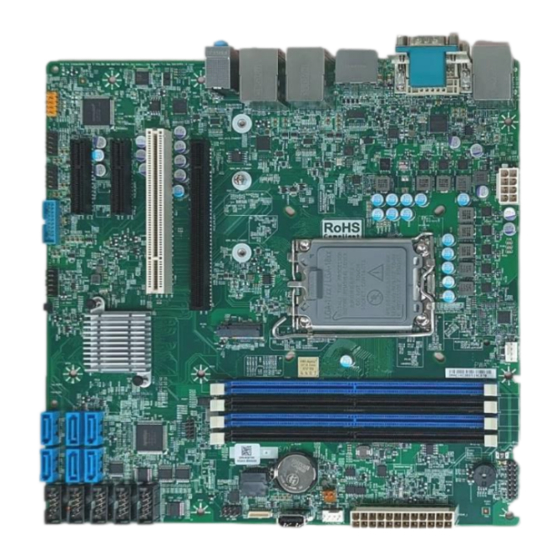
— — Product Nomenclature and Function GMB-MQ67000 Reference Manual 1. Product Overview Connectors of the product are shown in the picture below. ◆ Top View - 17 -... -
Page 18: Jumper List & Setting
GMB-MQ67000 Reference Manual 2. Jumper List & Setting For users to customize GMB-MQ67000 features. In the following sections, short means covering a jumper cap over jumper pins; Open or N/C (not connected) means removing a jumper cap from jumper pins. Users can refer to below Top view picture and tables for jumper positions, functions, and signal description. -
Page 19: Connector List
— — Product Nomenclature and Function GMB-MQ67000 Reference Manual 3. Connector List Ref. Connector Function AUDJ 1 Line-in, Line-out, Mic-in / 3.5mm Audio Jack J47A 2.5GbE /RJ45 Connector J47B USB3.2_Gen2 / Type A Connector J52A 2.5GbE /RJ45 Connector J52B USB3.2_Gen2 / Type A Connector... - Page 20 — — Product Nomenclature and Function GMB-MQ67000 Reference Manual J53A GbE /RJ45 Connector J53B USB3.2_Gen2/Type A Connector ATX8P_1 CPU Power Connector 8P / ATX24P_1 ATX Power Connector 24P / CPU_1 CPU Socket LGA1700 J_CPU_FAN1 CPU FAN connector DIMM1~4 DDR5 DIMM Socket 288P DIO_HDR1 4bit in/ 4bit out + Power button Signal Pin HDR.
-
Page 21: Atx Power Connector 24P (Atx24P_1)
— — Product Nomenclature and Function GMB-MQ67000 Reference Manual 1. ATX Power Connector 24P (ATX24P_1) ATX24P_1 PIN No. Signal Description PIN No. Signal Description 3.3V -12V ATX_PSON# PG_ATX 5V_SB 2. CPU Power Connector 4P (ATX8P_1) JPWR2 PIN No. Signal Description PIN No. -
Page 22: Front Panel Io Hdr. (J_Fio_1)
— — Product Nomenclature and Function GMB-MQ67000 Reference Manual 3. Front Panel IO HDR. (J_FIO_1) Pitch:2.54mm PIN No. Signal Description PIN No. Signal Description PWR LED + Speaker + PWR LED - SATA_LED+ SATA_LED- Speaker - RST_SW PWR_SW 4. CPU FAN Connector (J_CPU_FAN1) PIN No. -
Page 23: System Fan Connector (J_Fio_Fan1)
— — Product Nomenclature and Function GMB-MQ67000 Reference Manual 5. System FAN Connector (J_FIO_FAN1) PIN No. Signal Description +12V Sense Control 6. SPI HDR. 7P (SPI_HDR1) Pitch: 2.54mm PIN No. Signal Description PIN No. Signal Description 3.3V_SPI SPI_CLK SPI_CS SPI_MIS1... -
Page 24: Usb2.0./ Type A (J49)
— — Product Nomenclature and Function GMB-MQ67000 Reference Manual 7. USB2.0./ Type A (J49) PIN No. Signal Description USB_VCC DATA- DATA+ USB_GND 8. SPI Connector (J64) PIN No. Signal Description 3.3V_SPI SPI_CLK SPI_IO3 SPI_MISI SPI_IO2 SPI_MISO RESET SPI_CS - 24 -... -
Page 25: Usb2.0 Pin Hdr. / Pitch 2.54Mm (J1,J2)
— — Product Nomenclature and Function GMB-MQ67000 Reference Manual 9. USB2.0 Pin HDR. / Pitch 2.54mm (J1,J2) Pitch: 2.54mm PIN No. Signal Description PIN No. Signal Description +5V_USB2 +5V_USB2 USB Dats(n) - USB Data(n+1) - USB Data(n) + USB Data(n+1) + 10.Front Panel USB3.0 Box HDR. -
Page 26: Bit Gpio Pin Hdr. 16P (Dio_Hdr1)
— — Product Nomenclature and Function GMB-MQ67000 Reference Manual 11. 8-bit GPIO Pin HDR. 16P (DIO_HDR1) Pitch:2.54mm PIN No. Signal Description PIN No. Signal Description 5V_GPIO 12V_GPIO SIO_GPI1 SIO_GPO1 SIO_GPI2 SIO_GPO2 SIO_GPI3 SIO_GPO3 SIO_GPI4 SIO_GPO4 SW_PWRBT SW_PWRBT 12. Front Panel Audio Connector (J_HDA_1) Pitch:2.54mm... -
Page 27: Sata 3.0 Connector (Sat1/Sat2/Sat3/Sat4/Sat5/Sat6)
— — Product Nomenclature and Function GMB-MQ67000 Reference Manual LINE2_L B_LINE2-JD SATA 3.0 Connector (SAT1/SAT2/SAT3/SAT4/SAT5/SAT6) PIN No. Signal Description SATA_TXP SATA_TXN SATA_RXN SATA_RXP M.2 Key M Socket (M2M1) M.2 Key M Socket (PCIe x4 Signal) The board has one mechanical connector key M, accepting type 22342/2280/22110 of M.2 SSD... -
Page 28: Rs-232 Connector (Com1~Com5)
— — Product Nomenclature and Function GMB-MQ67000 Reference Manual 15. RS-232 Connector (COM1~COM5) COM1~COM5 (Pitch 2.54mm/ Box header) COM1 to COM5 provide five serial port connections and support RS-232 function. Pitch:2.54mm PIN No. Signal Description PIN No. Signal Description DCD(n) -
Page 29: Com6 Connector Db-9P (Com6)
— — Product Nomenclature and Function GMB-MQ67000 Reference Manual 17. COM6 Connector DB-9P (COM6) COM5 (with RS-232/422/485) The pin function of COM5 is based on BIOS setting. Signal Description PIN No. RS-232C RS-422 RS-485 Data- Data+ - 29 -... -
Page 30: Dvi-I Connector (Dvi-I)
— — Product Nomenclature and Function GMB-MQ67000 Reference Manual 18. DVI-I Connector (DVI-I) PIN No. Signal Description PIN No. Signal Description PIN No. Signal Description DATA2(-) N.C. RED+ DATA2(+) GREEN DATA2 SHIELD BLUE N.C. HSYNC N.C. DATA0(-) DDC CLK DATA0(+) -
Page 31: Display Port Connector (J54A)
— — Product Nomenclature and Function GMB-MQ67000 Reference Manual 19. Display Port Connector (J54A) PIN No. Signal Description PIN No. Signal Description ML_Lane 0(+) ML_Lane 0(-) ML_Lane 1(+) ML_Lane 1(-) ML_Lane 2(+) ML_Lane 2(-) ML_Lane 3(+) ML_Lane 3(-) AUX_CH(+) AUX_CH(-)... -
Page 32: Hdmi Connector (J54B)
— — Product Nomenclature and Function GMB-MQ67000 Reference Manual 20. HDMI Connector (J54B) PIN No. Signal Description PIN No. Signal Description HDMI1 DATA2(+) HDMI1 DATA2(-) HDMI1 DATA1(+) HDMI1 DATA1(-) HDMI1 DATA0(+) HDMI1 DATA0(-) HDMI1 CLK(+) HDMI1 CLK(-) HDMI1 DDC_SCL HDMI1 DDC_SDA... -
Page 33: Rj45+Usb3.0 Connector (J47/J52)
— — Product Nomenclature and Function GMB-MQ67000 Reference Manual 21. RJ45+USB3.0 Connector (J47/J52) RJ45 Port LED Indications : RJ45 LEDs for display of network status: Speed LED Speed LED Activity LED State Description No Link 10/100 Mbps data rate Orange... -
Page 34: Rj45+Usb2.0 Connector (J53)
— — Product Nomenclature and Function GMB-MQ67000 Reference Manual PIN No. Signal Description PIN No. Signal Description USB RX- USB D- USB RX+ USB D+ USB TX- USB TX+ 22. RJ45+USB2.0 Connector (J53) PIN No. Signal Description PIN No. Signal Description... - Page 35 — — Product Nomenclature and Function GMB-MQ67000 Reference Manual RJ45 Port LED Indications : RJ45 LEDs for display of network status: Speed LED Speed LED Activity LED State Description No Link 10 Mbps data rate Green 100 Mbps data rate...
-
Page 36: Watch-Dog Timer
— — Product Nomenclature and Function GMB-MQ67000 Reference Manual 23. Watch-Dog Timer The watchdog timer serves as a safeguard against possible system lock-up in your industrial computer system. In most industrial environments, there are heavy equipment, generators, high- voltage power lines, or power drops that have adverse effects on your computer system. For instance, when a power drop occurs, it could cause the CPU to come to a halt state or enter into an infinite loop, resulting in a system lock-up. - Page 37 — — Product Nomenclature and Function GMB-MQ67000 Reference Manual The following example is written in Intel8086 assembly language. ;=============== ;<WDT Initial> ;=============== ;------------------------------------------- ;Enter the extended function mode ;------------------------------------------- MOV DX,2EH MOV AL,87H OUT DX,AL OUT DX,AL ;---------------------------------------------- ;Select logical device WDT(number 8) ;----------------------------------------------...
- Page 38 — — Product Nomenclature and Function GMB-MQ67000 Reference Manual OUT DX,AL ;------------------------------------------ ;Exit the extended function mode ;------------------------------------------ MOV DX,2EH MOV AL,AAH OUT DX,AL ;=============================== ;<WDT START: counter set and a start> ;=============================== ;--------------------------------------------- ;Enter the extended function mode ;---------------------------------------------...
- Page 39 — — Product Nomenclature and Function GMB-MQ67000 Reference Manual OUT DX,AL ;--------------------------------------- ;Exit the extended function mode ;--------------------------------------- MOV DX,2EH MOV AL,AAH OUT DX,AL ;============== ;<WDT STOP> ;============== ;----------------------------------------- ;Enter the extended function mode ;----------------------------------------- MOV DX,2EH MOV AL,87H OUT DX,AL OUT DX,AL ;-----------------------------------...
- Page 40 — — Product Nomenclature and Function GMB-MQ67000 Reference Manual OUT DX,AL ;----------------------------------- ;Exit the extended function mode ;----------------------------------- MOV DX,2EH MOV AL,AAH OUT DX,AL CAUTION The timer’s intervals have a tolerance of ± 2 seconds. ⚫ - 40 -...
-
Page 41: Bios Setup
BIOS Setup This section describes AMI’s Setup program built into the FLASH ROM BIOS. - 41 -... -
Page 42: Introduction
— — BIOS Setup GMB-MQ67000 Reference Manual 1. Introduction This chapter discusses American Megatrends’ (AMI) Setup program built into the FLASH ROM BIOS. The Setup program allows users to modify the basic system configuration. This special information is then stored in FLASH ROM so that it retains the Setup information when the power is turned off. -
Page 43: Using Setup
— — BIOS Setup GMB-MQ67000 Reference Manual 2. Using Setup In general, you use the arrow keys to highlight items, press <Enter> to select, use the PageUp and PageDown keys to change entries, press <F1> for help and press <Esc> to quit. The following table provides more detail about how to navigate in the Setup program using the keyboard. -
Page 44: Main Menu
— — BIOS Setup GMB-MQ67000 Reference Manual 2. Main Menu When the setup program (Aptio Startup Utility) is started, the main menu will be displayed. Navigate through the various tabs by pressing the right and left arrow keys. - 44 -... -
Page 45: Setup Items
— — BIOS Setup GMB-MQ67000 Reference Manual 1. Setup Items The selectable tabs are as follows. Main View the basic system structure and configure the language settings and the date and time settings. Advanced Specify the detailed functions that can be set on the system used. -
Page 46: Main
— — BIOS Setup GMB-MQ67000 Reference Manual 3. Main View the basic system structure. The following items are displayed. Indication item of the main menu Item Indication Example Explanation BIOS Version 08830X07a Displays the BIOS Version Build Date 10/31/2023 Displays the BIOS creation date. -
Page 47: Advanced
— — BIOS Setup GMB-MQ67000 Reference Manual 4. Advanced Specify the detailed system functions. The following items are available. Onboard Device Onboard Device Configuration. CPU Configuration CPU Configure Parameters VDM Setup menu VDM Configure settings. Trusted Computing Configure the trusted computing settings. -
Page 48: Onboard Device
— — BIOS Setup GMB-MQ67000 Reference Manual 1. Onboard Device Onboard Device Item Options Description Enable/Disable processor Enabled Turbo Mode (require EMTTM Turbo Mode Disabled enabled too),auto means enabled. Do not change this setting. S0 State State after G3 When power is re-applied... - Page 49 — — BIOS Setup GMB-MQ67000 Reference Manual Item Options Description unconditionally disabled Enabled = HD will be unconditionally enabled Enabled Chassis Intrusion Configure Chassis Intrusion. Disabled Enabled J52 USB PWR1 under LAN i225 J52 under USB power Control Disabled Enabled...
-
Page 50: Cpu Configuration
— — BIOS Setup GMB-MQ67000 Reference Manual 2. CPU Configuration CPU Configuration (CPU Configure Parameters) - 50 -... -
Page 51: Vdm Configuration
— — BIOS Setup GMB-MQ67000 Reference Manual 3. VDM Configuration VDM Configuration settings Item Options Description Enabled Enable Disable Enable / Disable to VDM controller. Disable (Enabled) VDM Enabled Item Options Description Enable VDM Global Enabled Enable / Disable to VDM Global mapping... - Page 52 — — BIOS Setup GMB-MQ67000 Reference Manual Item Options Description Enabled Enable / Disable system acceleration with Intel® Intel® Optane™ Memory Disable Optane™ Memory feature. Enable / Disable to VDM ZPOOD Enabled ZPOOD The option is only needed to be enabled is when Disable ZPOOD is connected in VMD mode.
-
Page 53: Trusted Configuration
— — BIOS Setup GMB-MQ67000 Reference Manual 4. TRUSTED Configuration TRUSTED Configuration Item Options Description Enable or Disable BIOS support for Security Device. Enable Security Device Support O.S will not show Security Device. TCG EFI protocol and Disable INITA interface will not be avaliable Schedule an operation for the Security Device. -
Page 54: Nct6126D Super Io Configuration
— — BIOS Setup GMB-MQ67000 Reference Manual 5. NCT6126D Super IO Configuration Super IO Configuration Item Options Description Serial Port 1 Configuration -IO=3F8h; IRQ=4 Refer to Serial Port 1 Configuration Serial Port 2 Configuration - IO=2F8h; IRQ=3 Refer to Serial Port 2 Configuration Serial Port 3 Configuration - IO=3E8h;... - Page 55 — — BIOS Setup GMB-MQ67000 Reference Manual Serial Port 3 Configuration Item Options Description Enabled Configure the operation settings for Serial Port Disabled serial port 3 Auto IO=3E8h; IRQ=7; IO=3E8h; IRQ=3,4,5,6,7,9,10,11,12; Select an optimal setting for super Change Settings IO=2E8h; IRQ=3,4,5,6,7,9,10,11,12;...
- Page 56 — — BIOS Setup GMB-MQ67000 Reference Manual Item Options Description 1T/1R RS422 3T/5R RS232 1T/1R RS485 TX Enable Low Active Configure serial port as Mode Configuration 1T/1R RS485 TX Enable High Active RS232/RS422/RS485 1T/1R RS422 with termination resistor 1T/1R RS485 with termination resistor...
-
Page 57: Hardware Monitor
— — BIOS Setup GMB-MQ67000 Reference Manual 6. Hardware Monitor View hardware monitor information such as the CPU temperature. Item Options Description If Enabled. POST monitors Voltage, Enabled Temperature ,and Fan status. If these Hardware Monitor Alert Enable Disabled values re out of range. BIOS display warning message and turn beep sound. -
Page 58: Network Stack Configuration
— — BIOS Setup GMB-MQ67000 Reference Manual 8. Network Stack Configuration (The figure shows on setting by enable) Network Stack Configuration Item Options Description Enabled Network Stack Enabled / Disable UEFI Netware Stack Disabled 9. NVMe Configuration (NVMe SSD will recognized when module installation) -
Page 59: Security
— — BIOS Setup GMB-MQ67000 Reference Manual 5. Security Administrator Password Set the Administrator Password. Press Enter to display the following screen for entering the password. Administrator Password Create New Password **** Confirm New Password [ **** Enter a password at least 3 characters long twice. - Page 60 — — BIOS Setup GMB-MQ67000 Reference Manual Secure Boot Item Options Description Secure boot feature is active if source boot is enable. Enabled Secure Boot Platform Key(PK) is enrolled and the Disabled system is in user mode. The mde change requires platform reset Secure Boot Mode options: Standard or Custom.
-
Page 61: Boot
— — BIOS Setup GMB-MQ67000 Reference Manual 6.Boot Configurate the settings boot devices and other devices Item Options Description Number of seconds to wait for setup Setup Prompt Timeout activation key. 65535(0xFFFF) means indefinite waiting. Set the NumLock status when the system Bootup NumLock State starts. - Page 62 — — BIOS Setup GMB-MQ67000 Reference Manual Item Options Description USB Floppy CD/DVD USB CD/DVD Hard Disk Boot Option #3 Set the system boot order. USB Key USB Hard Disk NVME Network Disabled USB Floppy CD/DVD USB CD/DVD Hard Disk Boot Option #4 Set the system boot order.
- Page 63 — — BIOS Setup GMB-MQ67000 Reference Manual Item Options Description USB Floppy CD/DVD USB CD/DVD Hard Disk Boot Option #8 USB Key Set the system boot order. USB Hard Disk NVME Network Disabled - 63 -...
-
Page 64: Save And Exit
— — BIOS Setup GMB-MQ67000 Reference Manual 7.Save and Exit Load/ Save setup items and exit the setup menu. - 64 -... -
Page 65: Event Logs
— — BIOS Setup GMB-MQ67000 Reference Manual 8. Event Logs Change Smbios Event Log Setting Item Options Description Enabled Change this enable or disable all features of Smbios Event Log smbios Event Logging during boot. Disabled Choose Options for erasing smbios Even... -
Page 66: Appendix
Appendix This section lists the specifications and the physical dimensions of the product, and the details of model name. - 66 -... -
Page 67: System Reference
— — Appendix GMB-MQ67000 Reference Manual 1. System Reference 1. Specifications Model Name GMB-MQ67000 ® Processor Intel / 13 Gen Core™ Processors CPU in LGA1700 socket up to 65W TDP ® Chipset Intel Q670 Chipset BIOS AMI UEFI BIOS ®... -
Page 68: Block Diagram
— — Appendix GMB-MQ67000 Reference Manual 2. Block Diagram - 68 -... -
Page 69: Installation
— — Appendix GMB-MQ67000 Reference Manual 3. Installation 1. CPU Installation 1. Make sure PC and all other peripheral devices are shut down. 2. Disconnect all power cords and cables. 3. Open the load plate then remove the plastic cap as below picture 1 and 2 showed. - Page 70 — — Appendix GMB-MQ67000 Reference Manual 4. Be careful to put CPU straight down into the socket. (Make sure socket keys and CPU pin1 are put at right location marked in below picture 3.) Press down on the socket cover and pull the lever down to secure the socket cover as picture 4 and picture 5 (Make sure CPU is inserted into socket properly before close socket cover.)
-
Page 71: Motherboard Installation
— — Appendix GMB-MQ67000 Reference Manual 2. Motherboard Installation Some components are very close to the mounting holes. Please take precautionary measure to avoid damaging these components when installing the motherboard. 3. Memory Installation 1. The DDR5 memory sockets are divided into A and B two channels, each has two sockets showed as below. -
Page 72: Rtc Battery Installation
— — Appendix GMB-MQ67000 Reference Manual 4. RTC Battery Installation Battery Install: Battery Remove: To Replace the Battery: 1. Ensure that the system is turned off and AC power cord is disconnected. 2. Gently press the metal clip as shown to release the battery. -
Page 73: List Of Optional Products
List of Optional Products This section lists optional items that can be used along with the product. - 73 -... -
Page 74: Optional Product
List of Optional Products GMB-MQ67000 Reference Manual 1. Optional Product Optional product items are as follows, please acquire them as required. Accessory Parts Name Product Code Description Visit the CONTEC website for the latest optional products. https://www.contec.com/ Download - 74 -... -
Page 75: Customer Support And Inquiry
Customer Support and Inquiry CONTEC provides the following support services for you to use CONTEC products more efficiently and comfortably. - 75 -... -
Page 76: Services
— — Customer Support and Inquiry GMB-MQ67000 Reference Manual 1. Services CONTEC offers the useful information including product manuals that can be downloaded through the CONTEC website. Download https://www.contec.com/download/ You can download updated driver software, firmware, and differential manuals in several languages. Membership registration (myCONTEC) is required to use the services. - Page 77 —— GMB-MQ67000 Reference Manual Revision History MONTH YEAR Summary of Changes February 2024 The First Edition - 77 -...
- Page 78 CONTEC CO., LTD. 3-9-31, Himesato, Nishiyodogawa-ku, Osaka 555-0025, Japan https://www.contec.com/ No part of this document may be copied or reproduced in any form by any means without prior written consent of CONTEC CO., LTD. GMB-MQ67000 Reference Manual NA09929 (LXDG251) [02202024]...
Need help?
Do you have a question about the GMB-MQ67000 and is the answer not in the manual?
Questions and answers