Table of Contents
Advertisement
Quick Links
Reference Manual
Industrial Mainboard
GMB-PTGL200/300/400
CONTENTS
Introduction .................................................................. 5
Safety Precautions .................................................... 11
Product Nomenclature and Function ............... 17
BIOS Setup .................................................................. 36
Appendix ...................................................................... 65
List of Optional Products ....................................... 81
Customer Support and Inquiry ............................ 83
Advertisement
Table of Contents

Subscribe to Our Youtube Channel
Related Manuals for Contec GMB-PTGL200


Summary of Contents for Contec GMB-PTGL200
- Page 1 Reference Manual Industrial Mainboard GMB-PTGL200/300/400 CONTENTS Introduction ..............5 Safety Precautions ............ 11 Product Nomenclature and Function ....17 BIOS Setup ..............36 Appendix ..............65 List of Optional Products ........81 Customer Support and Inquiry ......83...
-
Page 2: Table Of Contents
Table of Contents Introduction ..............5 1. Related Manuals ..............................6 2. About the Product ..............................7 3. Features ..................................8 4. Supported OS ................................9 5. Product Configuration List ..........................10 Safety Precautions ............11 1. Safety Information ............................... 12 2. Handling Precautions ............................13 1. - Page 3 Table of Contents 2. Using Setup ..............................38 3. Getting Help ..............................38 4. In Case of Problems ............................. 38 5. A Final Note About Setup .......................... 38 2. Main Menu ................................39 1. Setup Items ..............................40 3. Main ..................................41 4.
- Page 4 Table of Contents Customer Support and Inquiry ........83 1. Services ..................................84 - 4 -...
-
Page 5: Introduction
Introduction This section provides necessary information of the product such as the outline, bundled items and manuals before actual use. - 5 -... -
Page 6: Related Manuals
— — Introduction GMB-PTGL200/300/400 Reference Manual 1. Related Manuals The manuals related to the product are listed below. Read them as necessary along with this document. ◆ Must Read the Following Manuals Name Purpose Contents How to get Read this when operating... -
Page 7: About The Product
Lake-UP3 Processor Core™ i3-1115G4E / i5-1145G7E / i7-1185G7E with Windows 10 IoT Enterprise 2021 (4 languages) supported. The industrial-grade GMB-PTGL200/300/400, with size of 100mm x 72mm, has high computing power, and various expansion slots make it well-suited for factory automation, intelligent transportation, digital signage, self-service kiosks, and medical applications. -
Page 8: Features
3. Features ◼ Intel ® Gen. Processor (Tiger Lake-UP3 platform) GMB-PTGL200-2LCF : Intel® Core™ i3-1115G4E GMB-PTGL200-3LCF : Intel® Core™ i3-1115G4E GMB-PTGL300-3LCF : Intel® Core™ i5-1145G7E GMB-PTGL400-3LCF : Intel® Core™ i7-1185G7E ◼ On Board LPDDR4x-3200 up to 16 GB by SKU ◼... -
Page 9: Supported Os
— — Introduction GMB-PTGL200/300/400 Reference Manual 4. Supported OS Windows®10 IoT Enterprise LTSC 2021 64 bit - 9 -... -
Page 10: Product Configuration List
Screw for fixing M.2 key E / M module (M2x5 NI) *1 The configuration and parts of this product as shown below. *2 The user's manual for this product is available as a PDF file through CONTEC’s Web site. Production Configuration Drawings... -
Page 11: Safety Precautions
Safety Precautions Understand the following definitions and precautions to use the product safely. Never fail to read them before using the product. - 11 -... -
Page 12: Safety Information
— — Safety Precautions GMB-PTGL200/300/400 Reference Manual 1. Safety Information This document provides safety information using the following symbols to prevent accidents resulting in injury or death and the destruction of equipment and resources. Understand the meanings of these labels to operate the equipment safely. -
Page 13: Handling Precautions
— — Safety Precautions GMB-PTGL200/300/400 Reference Manual 2. Handling Precautions WARNING Always check that the power supply is turned off before connecting or disconnecting power ⚫ cables. Do not modify the product. ⚫ Always turn off the power before inserting or removing circuit boards or cables. - Page 14 To prevent corruption of files, always shutdown the OS before turning off this product. ⚫ CONTEC reserves the right to refuse to service a product modified by the user. ⚫ In the event of failure or abnormality (foul smells or excessive heat generation), unplug the ⚫...
-
Page 15: Fcc Part 15 Class B Notice
— — Safety Precautions GMB-PTGL200/300/400 Reference Manual 1. FCC PART 15 Class B Notice NOTE This equipment has been tested and found to comply with the limits for a Class B digital device, pursuant to part 15 of the FCC Rules. These limits are designed to provide reasonable protection against harmful interference when the equipment is operated in a commercial environment. -
Page 16: Security Warning
— — Safety Precautions GMB-PTGL200/300/400 Reference Manual 3. Security Warning When connecting to the network, be aware of security-related problems. See the examples of Security measures below and set up the product properly along with the network devices. 1. Information security risks Unauthorized access from the outside through a network could cause the system halt, data ⚫... -
Page 17: Product Nomenclature And Function
Product Nomenclature and Function This section describes product component names and their functions, pin assignment of each connector. - 17 -... -
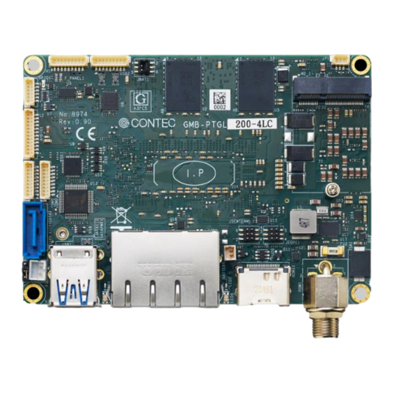
Page 18: Product Overview
— — Product Nomenclature and Function GMB-PTGL200/300/400 Reference Manual 1. Product Overview connectors of the product are shown in the picture below. ◆ Top View - 18 -... -
Page 19: Jumper List & Led Indicator
GMB-PTGL200/300/400 Reference Manual 2. Jumper List & LED indicator For users to customize GMB-PTGL200/300/400 features. In the following sections, short means covering a jumper cap over jumper pins; Open or N/C (not connected) means removing a jumper cap from jumper pins. Users can refer to below Top view picture and tables for jumper positions, functions, and signal description. -
Page 20: Connector List
— — Product Nomenclature and Function GMB-PTGL200/300/400 Reference Manual 3.Connector List - 20 -... - Page 21 — — Product Nomenclature and Function GMB-PTGL200/300/400 Reference Manual Ref. Connector Function Top Side DC-IN Power Connector HDMI1 HDMI connector LAN1 Dual RJ45 Connector (1GbE +2.5GbE) USB1 USB 3.1 Gen2/ Dual Type A connector SATAPWR1 SATA Power Connector (JST: B2B-PH-K-S(LF)(SN))
-
Page 22: Dc-In Power Connector (Cn1)
— — Product Nomenclature and Function GMB-PTGL200/300/400 Reference Manual 1. DC-IN Power Connector (CN1) PIN No. Signal Description DC-IN (+) GND (-) To supply the power, always use the power supply listed below. Rated input voltage: 12 – 24 VDC Range of input voltage: 10.8 –... -
Page 23: Dual Rj-45 Lan Port (Lan1)
— — Product Nomenclature and Function GMB-PTGL200/300/400 Reference Manual PIN No. Signal Description PIN No. Signal Description HDMI1 DATA2(+) HDMI1 DATA2(-) HDMI1 DATA1(+) HDMI1 DATA1(-) HDMI1 DATA0(+) HDMI1 DATA0(-) HDMI1 CLK(+) HDMI1 CLK(-) HDMI1 DDC_SCL HDMI1 DDC_SDA HDMI1_5V HDMI1 HPD 3. -
Page 24: Usb3.1 Gen2 Connector (Usb1)
— — Product Nomenclature and Function GMB-PTGL200/300/400 Reference Manual PIN No. Signal Description TX1+ TX1- TX2+ TX3+ TX3- TX2- TX4+ TX4- 4. USB3.1 Gen2 Connector (USB1) USB1 (Dual USB Type A stack) PIN No. Signal Description PIN No. Signal Description... -
Page 25: Sata Power Connector (Satapwr1)
— — Product Nomenclature and Function GMB-PTGL200/300/400 Reference Manual 5. SATA Power Connector (SATAPWR1) SATAPWR1 PIN No. Signal Description +5Vdc 6. SATA Connector (SATA1) SATA1 SATA1 SATA 3.0 Gen III(6 Gbps)Port . PIN No. Signal Description SATA_TXP SATA_TXN - 25 -... -
Page 26: Serial Port Rs-232 9-Pin (Com2)
— — Product Nomenclature and Function GMB-PTGL200/300/400 Reference Manual SATA_RXN SATA_RXP 7. Serial Port RS-232 9-Pin (COM2) PIN No. Signal Description DCD 2 RX 2 TX 2 DTR 2 DSR 2 RTS 2 CTS 2 RI 2 - 26 -... -
Page 27: Serial Port Rs-232/422/485 /9P (Com1)
— — Product Nomenclature and Function GMB-PTGL200/300/400 Reference Manual 8. Serial Port RS-232/422/485 /9P (COM1) Signal Description PIN No. RS 232 RS 422 RS 485 DCD 1 TX(-) Data(-) RX 1 TX(+) Data(+) TX 1 RX(+) DTR 1 RX(-) DSR 1... -
Page 28: Audio Connector 12-Pin (Audio1)
— — Product Nomenclature and Function GMB-PTGL200/300/400 Reference Manual 9. Audio Connector 12-Pin (AUDIO1) AUDIO1 PIN No. Signal Description AGND LIN2_OUT_R LIN2_OUT_L A_LINE1_JD_R AGND MIC1_R MIC1_L A_MIC1_JD AGND - 28 -... -
Page 29: Bit Gpio Pin Header 6-Pin (Gpio1)
— — Product Nomenclature and Function GMB-PTGL200/300/400 Reference Manual 10. 4-bit GPIO Pin header 6-pin (GPIO1) GPIO1 PIN No. Signal Description DIO_CN_1 DIO_CN_2 DIO_CN_3 DIO_CN_4 +5V_SB The General-Purpose Input/Output (GPIO) pin header 11. Front Panel Pin HDR /9P (F_PANEL1) F-PANE 1... -
Page 30: Usb2.0 Connector 9-Pin (Usb2)
— — Product Nomenclature and Function GMB-PTGL200/300/400 Reference Manual PIN No. Signal Description PWR LED (+) PWR LED (-) HDDLED(+) HDDLED(-) RST_SW PWRBTN# F_PANEL1 1 - 2 PWR LED 3 – 4 SATA LED 6 - 7 RST SW 8 - 9 PWR SW 12. -
Page 31: Rtc Battery Connector (Batter1)
— — Product Nomenclature and Function GMB-PTGL200/300/400 Reference Manual USB6_C 13. RTC Battery Connector (BATTER1) BATTER1 PIN No. Signal Description +3V DC (+) GND (-) CAUTION The connector of RTC Battery has (+) and (-) polarities. ⚫ - 31 -... -
Page 32: Key E Socket (M2_1)
— — Product Nomenclature and Function GMB-PTGL200/300/400 Reference Manual 14. M.2 Key E Socket (M2_1) M2_1 H= 8.5mm 2230 Screw Size Thread Size :M2 Total length: 3mm Thread length: 2mm Head diameter: 4mm M.2 E Key Socket (PCIe by1 lanes + USB 2.0 Signal) The board has one mechanical connector key E, accepting type 2230 of M.2 modules ( H-4.2mm) -
Page 33: Edp Connector/ 30-Pin (Cn3)
— — Product Nomenclature and Function GMB-PTGL200/300/400 Reference Manual 16. eDP Connector/ 30-Pin (CN3) (Bottom side) PIN No. Signal Description EDP_3V3 EDP_3V3 EDP_3V3 LVDS_A_TXL-2_C LVDS_A_TXL+2_C LVDS_A_TXL-1_C LVDS_A_TXL+1_C LVDS_A_TXL-0_C LVDS_A_TXL+0_C LVDS_A_TXL-3_C LVDS_A_TXL+3_C EDP_AUXN EDP_AUXP EDP_BL_PWM EDP_VDD_EN EDP_BL_EN EDP_HPD_R Note: EDP_12V - 33 -... -
Page 34: Debug Port (Cn2)
— — Product Nomenclature and Function GMB-PTGL200/300/400 Reference Manual EDP_12V EDP_12V EDP_12V 17. Debug port (CN2) Debug Port (factory use only) 18. System FAN Connector 4-Pin ( SYS_FAN1) (Bottom side) SYS_FAN1 PIN No. Signal Description +12Vdc FAN_SPEED_OUT FAN_PWM 19. M.2 Key M Socket (M2_2) -
Page 35: Spi Connector 9-Pin (Spi 1)
— — Product Nomenclature and Function GMB-PTGL200/300/400 Reference Manual M.2 Key M Socket (PCIe by 4 lanes+ SATA Signal) The board has one mechanical connector key M, accepting type 2242 of M.2 modules (H-8.5mm) 20. SPI Connector 9-Pin (SPI 1) -
Page 36: Bios Setup
BIOS Setup This section describes AMI’s Setup program built into the FLASH ROM BIOS. - 36 -... -
Page 37: Introduction
— — BIOS Setup GMB-PTGL200/300/400 Reference Manual 1. Introduction The BIOS setup program allows users to modify the basic system configuration. In this following chapter will describe how to access the BIOS setup program and the configuration options that may be changed. -
Page 38: Using Setup
— — BIOS Setup GMB-PTGL200/300/400 Reference Manual 2. Using Setup In general, you use the arrow keys to highlight items, press <Enter> to select, use the PageUp and PageDown keys to change entries, press <F1> for help and press <Esc> to quit. The following table provides more detail about how to navigate in the Setup program using the keyboard. -
Page 39: Main Menu
— — BIOS Setup GMB-PTGL200/300/400 Reference Manual 2. Main Menu Once you enter the Aptio Setup Utility, the Main Menu will appear on the screen. The Main Menu allows you to select from several setup functions and exit choices. Use the arrow keys to select among the items and press <Enter>... -
Page 40: Setup Items
— — BIOS Setup GMB-PTGL200/300/400 Reference Manual 1. Setup Items The selectable tabs are as follows. Main Record some basic hardware configurations in your computer and set the system clock. Advanced configure your CPU and other system devices for basic operation through the following sub-menus. -
Page 41: Main
— — BIOS Setup GMB-PTGL200/300/400 Reference Manual 3. Main View the basic system structure. The following items are displayed. Indication item of the main menu Item Indication Example Explanation Project Version PTGL 0.19 x64 Displays the BIOS version. Build Date and Time 11/01/2023 Displays the BIOS creation date and time. -
Page 42: Advanced
— — BIOS Setup GMB-PTGL200/300/400 Reference Manual 4. Advanced This section allows you to configure your CPU and other system devices for basic operation through the following sub-menus. - 42 -... -
Page 43: Cpu Configuration
— — BIOS Setup GMB-PTGL200/300/400 Reference Manual 1. CPU Configuration CPU Configuration Item Options Description When enabled, a VMM can utilize the Intel (VMX) Virtualization Disabled additional hardware capabilities Enabled Technology provided by vanderpool technology. Number of cores to enable in each... -
Page 44: Pch-Fw Configuration
— — BIOS Setup GMB-PTGL200/300/400 Reference Manual 2. PCH-FW Configuration PCH-FW Configuration Item Options Description Disabled When Disabled ME will be put into ME ME State Enabled temporarily disabled mode. Firmware Update Configuration ⚫ Item Options Description Disabled ME FW Image Re-Flash... -
Page 45: Trusted Computing
— — BIOS Setup GMB-PTGL200/300/400 Reference Manual 3. Trusted Computing Security Device Support Item Options Description Enables or Disables BIOS support for security device. Disable Security Device Support O.S. will not show Security Device. TCG EFI protocol Enable and INT1A interface will not be available. - Page 46 — — BIOS Setup GMB-PTGL200/300/400 Reference Manual Item Options Description TPM 1.2 will restrict support to TPM 1.2 Devices. TPM TPM 1.2 2.0 will restrict support to TPM 2.0 Devices.Auto will Device Select TPM 1.3 support both with the default set to TPM2.0 Devices if Auto not found.TPM 1.2 Deices will be enumerated.
-
Page 47: Acpi Settings
— — BIOS Setup GMB-PTGL200/300/400 Reference Manual ACPI Settings ACPI Settings Item Options Description Disabled Enables or Disables BIOS ACPI auto Enable ACPI Auto Configuration Enabled configuration. - 47 -... -
Page 48: Smart Settings
— — BIOS Setup GMB-PTGL200/300/400 Reference Manual 5. SMART Settings SMART Self-Test Item Options Description Disabled SMART Self Test Run SMART Self-Test on all HDs during POST. Enabled - 48 -... -
Page 49: F81804 Super Io Configuration
— — BIOS Setup GMB-PTGL200/300/400 Reference Manual 5. F81804 Super IO Configuration F81804 Super IO Configuration Item Options Description Serial Port 1 Configuration Refer to Serial Port 1 Serial Port 2 Configuration Refer to Serial Port 2 Digital I/O Configuration... - Page 50 — — BIOS Setup GMB-PTGL200/300/400 Reference Manual Serial Port 2 Configuration Item Options Description Disabled Serial Port Enable or Disable Serial Port (COM). Enabled Auto IO=2F8h: IRQ=3; IO=3F8h: IRQ=3,4,5,6,7,9,10,11,12; Select an optimal settings for super IO Change Settings IO=2F8h: IRQ=3,4,5,6,7,9,10,11,12;...
-
Page 51: H/W Monitor
— — BIOS Setup GMB-PTGL200/300/400 Reference Manual 6. H/W Monitor View hardware monitor information such as the CPU temperature. Smart Fan Configuration Item Options Description General-purpose I/O Thermal cruise mode Digital I/O Pin 1 Input output selected PWM Manual Mode... -
Page 52: Switchable Graphices
— — BIOS Setup GMB-PTGL200/300/400 Reference Manual 7. Switchable Graphices Default : Muxless 8. USB Configuration USB Configuration Item Options Description Enable Legacy USB support. Enabled Auto option disables legacy support if no USB Legacy USB Support devices are connected. Disable option will... - Page 53 — — BIOS Setup GMB-PTGL200/300/400 Reference Manual Item Options Description 1 sec 5 sec The time-out value for Control, Bulk, and USB transfer time-out 10 sec interrupt transfer 20 sec 10 sec 20 sec USB mass storage device Start unit command...
-
Page 54: Network Stack Configuration
— — BIOS Setup GMB-PTGL200/300/400 Reference Manual 9. Network Stack Configuration Network stack: Disabled Network stack: Enabled - 54 -... -
Page 55: Nvme Configuration
— — BIOS Setup GMB-PTGL200/300/400 Reference Manual 10. NVMe Configuration NVMe Configuration : (When Device installation) Item Options Description Select either Short or Extended Self Test. Short Short option will take couple of minutes and Self Test Option extended option will take several minutes to... -
Page 56: Intel® Ethernet Controller I225-Lm
— — BIOS Setup GMB-PTGL200/300/400 Reference Manual 11. Intel® Ethernet Controller I225-LM Configure Gigabit Ethernet device parameters 12. Driver Health Provides Health Status for the Drivers/Controllers - 56 -... -
Page 57: Chipset
— — BIOS Setup GMB-PTGL200/300/400 Reference Manual 5. Chipset 1. System Agent (SA) Configuration System Agent (SA) Configuration Graphic Configuration Item Options Description Auto IGFX Select which of IGFX/PEG/PCI graphic Primary Display PEG Slot device should be primary display or select HG for switchable Gfx. - Page 58 — — BIOS Setup GMB-PTGL200/300/400 Reference Manual Item Options Description Disabled PSMI SUPPORT PSMI Enable / Disable Enabled Select DVMT5.0 pre-allocated (Fixed) DVMT Pre-Allocated graphic memory size used by the internal graphic device. 32M/F7 128M Select DVMT5.0 total graphic memory...
- Page 59 — — BIOS Setup GMB-PTGL200/300/400 Reference Manual Item Options Description 800 x 600 Single Channel 18bit 1024 x 768 Single Channel 18bit 1024 x 768 Single Channel 24bit 1280 x 768 Single Channel 18bit 1280 x 800 Single Channel 18bit...
-
Page 60: Pch-Io Configuration
— — BIOS Setup GMB-PTGL200/300/400 Reference Manual 2. PCH-IO Configuration PCH-IO Configuration SATA and RST Configuration Item Options Description Enabled SATA Controller(s) Enable/ Disable SATA Device Disabled SATA Mode Selection AHCI Determines how SATA controllers operate HD Audio Configuration Item... - Page 61 — — BIOS Setup GMB-PTGL200/300/400 Reference Manual Item Options Description Enabled Onboard LAN B Controller Enable/ Disable onboard NIC Disabled Enabled Wake on LAN Enable/ Disable integrated LAN to wake the system Disabled Enabled Wake on RI Enable/ Disable RI to wake the system...
-
Page 62: Security
— — BIOS Setup GMB-PTGL200/300/400 Reference Manual 6. Security Secure Boot Item Options Description Secure Boot feature is Active if Secure Boot is Enabled, Enabled Secure Boot Platform Key(PK) is enrolled and the System is in Disabled User mode. The mode change requires platform reset Secure Boot mode options: Standard or Custom. -
Page 63: Boot
— — BIOS Setup GMB-PTGL200/300/400 Reference Manual 7.Boot Boot Item Options Description Number of seconds to wait for setup Setup Prompt Timeout activation key. 65535(0xFFFF) means indefinite waiting. Bootup NumLock State Select the keyboard Numlock state Enabled Quiet Boot Enables or disables quite boot option... -
Page 64: Save And Exit
— — BIOS Setup GMB-PTGL200/300/400 Reference Manual 8.Save and Exit As shown in the figure : Please refer to the corresponding window message operation for each option. - 64 -... -
Page 65: Appendix
Appendix This section lists the specifications and components suggestion, block diagram, driver installation, and mechanical drawing. - 65 -... -
Page 66: System Reference
— — Appendix GMB-PTGL200/300/400 Reference Manual 1. System Reference 1. Specifications Model Name GMB-PTGL200-2LCF GMB-PTGL200-3LCF GMB-PTGL300-3LCF GMB-PTGL400-3LCF 11th Intel® Embedded Tiger Lake-UP3 Intel® Core™ i3- Intel® Core™ i3- Intel® Core™ i5- Intel® Core™ i7- 1115G4E 1115G4E 1145G7E 1185G7E Chipset SoC (System on chipset) - Page 67 — — Appendix GMB-PTGL200/300/400 Reference Manual Hardware System monitor(Voltage,Fan Speed and Temperature) Monitoring Power 12 ~24 VDC ±10% ; lockable DC-Jack Operation Temperature: 0~60° C (with 0.7m/s airflow) Environmental Storage Temperature: -10 to 70° C Humidity: 10 to 90% non-condensing Dimension 2.5"...
-
Page 68: Block Diagram
— — Appendix GMB-PTGL200/300/400 Reference Manual 2. Block Diagram - 68 -... -
Page 69: Dimension
— — Appendix GMB-PTGL200/300/400 Reference Manual 3. Dimension - 69 -... -
Page 70: Installation
— — Appendix GMB-PTGL200/300/400 Reference Manual 4. Installation 1. Mainboard Installation Some components are very close to the mounting holes. Please take precautionary measure to avoid damaging these components when installing the motherboard. 2. M.2 Slot (Key E, 2230) Module Installation Insert the module contact pins into the module slot and press the module down, aligning the notch with the inner screw location. -
Page 71: Slot (Key M 2242)Module Installation
— — Appendix GMB-PTGL200/300/400 Reference Manual 3. M.2 Slot (Key M 2242)Module Installation 1) Insert the module contact pins into the module slot and press the module down, aligning the notch with the inner screw location. 2) Use M2x5 screw to fix Module as show below. -
Page 72: Serial I/O Address And Register Function
— — Appendix GMB-PTGL200/300/400 Reference Manual 5.Serial I/O Address and Register Function The following table lists the I/O addresses in case of SERIAL A. I/O Port Addresses I/O address DLAB Read/Write Register 03F8H Transmitter holding register Receiver buffer register Divisor latch register (LSB) - Page 73 — — Appendix GMB-PTGL200/300/400 Reference Manual I/O address Description IER: Interrupt Enable Register [DLAB=0] 03F9H IIR: Interrupt Identification Register 03FAH LCR: Line Control Register 03FBH - 73 -...
- Page 74 — — Appendix GMB-PTGL200/300/400 Reference Manual Description I/O address MCR: Modem Control Register 03FCH LSR: Line Status Register 03FDH MSR: Modem Status Register 03FEH SCR: Scratchpad Register This is an 8-bit, readable/writable register which is available to the 03FFH user to allow data to be saved temporarily.
- Page 75 — — Appendix GMB-PTGL200/300/400 Reference Manual Baud Rate Settings A baud rate is set by software by dividing the clock input (1.8432MHz). The baud rate in terms of hardware can be set to a maximum of 115,200 bps for SERIAL Port. The baud rates available in practice depend on the operating environment (cable, software, etc.).
-
Page 76: Watch-Dog-Timer
— — Appendix GMB-PTGL200/300/400 Reference Manual 6.Watch-Dog-Timer The watchdog timer serves as a safeguard against possible system lock-up in your industrial computer system. In most industrial environments, there are heavy equipment, generators, high- voltage power lines, or power drops that have adverse effects on your computer system. For instance, when a power drop occurs, it could cause the CPU to come to a halt state or enter into an infinite loop, resulting in a system lock-up. - Page 77 — — Appendix GMB-PTGL200/300/400 Reference Manual Example programming The following example is written in Intel8086 assembly language. ;=============== ;<WDT Initial> ;=============== ;------------------------------------------- ;Enter the extended function mode ;------------------------------------------- MOV DX,2EH MOV AL,87H OUT DX,AL OUT DX,AL ;---------------------------------------------- ;Select logical device WDT(number 8) ;----------------------------------------------...
- Page 78 — — Appendix GMB-PTGL200/300/400 Reference Manual MOV DX,2FH MOV AL,00H OUT DX,AL ;------------------------------------------ ;Exit the extended function mode ;------------------------------------------ MOV DX,2EH MOV AL,AAH OUT DX,AL ;=============================== ;<WDT START: counter set and a start> ;=============================== ;--------------------------------------------- ;Enter the extended function mode ;---------------------------------------------...
- Page 79 — — Appendix GMB-PTGL200/300/400 Reference Manual MOV AL,0FH ;0FH=15Sec ;---------------------------------------------------------------------------------- OUT DX,AL ;--------------------------------------- ;Exit the extended function mode ;--------------------------------------- MOV DX,2EH MOV AL,AAH OUT DX,AL ;============== ;<WDT STOP> ;============== ;----------------------------------------- ;Enter the extended function mode ;----------------------------------------- MOV DX,2EH MOV AL,87H...
- Page 80 — — Appendix GMB-PTGL200/300/400 Reference Manual MOV AL,00H ;----------------------------------- OUT DX,AL ;----------------------------------- ;Exit the extended function mode ;----------------------------------- MOV DX,2EH MOV AL,AAH OUT DX,AL CAUTION The timer’s intervals have a tolerance of ± 2 seconds. ⚫ - 80 -...
-
Page 81: List Of Optional Products
List of Optional Products This section lists optional items that can be used along with the product. - 81 -... -
Page 82: Optional Product
SATA+ Power Cable LXCU821 L=250mm L=100mm USB 2.0 Cable LXCU831 L=250mm COM Cable LXCU841 Audio Cable LXCU851 L=200mm GPIO Cable (DIO) LXCU861 L=200mm L=250mm FRONT Panel Cable LXCU871 Visit the CONTEC website for the latest optional products. https://www.contec.com/ Download - 82 -... - Page 83 Customer Support and Inquiry CONTEC provides the following support services for you to use CONTEC products more efficiently and comfortably. - 83 -...
- Page 84 — — Customer Support and Inquiry GMB-PTGL200/300/400 Reference Manual 1. Services CONTEC offers the useful information including product manuals that can be downloaded through the CONTEC website. Download https://www.contec.com/download/ You can download updated driver software, firmware, and differential manuals in several languages. Membership registration (myCONTEC) is required to use the services.
- Page 85 No part of this document may be copied or reproduced in any form by any means without ⚫ prior written consent of CONTEC CO., LTD. CONTEC CO., LTD. makes no commitment to update or keep current the information contained ⚫ in this document.
- Page 86 CONTEC CO., LTD. 3-9-31, Himesato, Nishiyodogawa-ku, Osaka 555-0025, Japan https://www.contec.com/ No part of this document may be copied or reproduced in any form by any means without prior written consent of CONTEC CO., LTD. GMB-PTGL200/300/400 Reference Manual NA09326(LXCC941) [12082023] Dec.2023 Edition...
Need help?
Do you have a question about the GMB-PTGL200 and is the answer not in the manual?
Questions and answers