Table of Contents
Advertisement
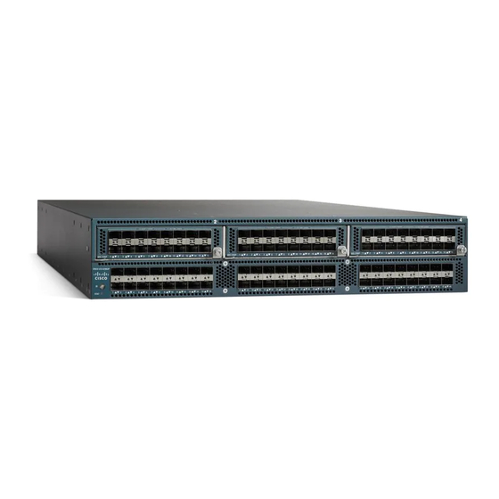
Cisco UCS 6200 Series Fabric Interconnect Hardware Installation Guide
First Published: 2012-07-19
Last Modified: 2018-03-06
Americas Headquarters
Cisco Systems, Inc.
170 West Tasman Drive
San Jose, CA 95134-1706
USA
http://www.cisco.com
Tel: 408 526-4000
800 553-NETS (6387)
Fax: 408 527-0883
Text Part Number: OL-24475-03
Advertisement
Table of Contents


Need help?
Do you have a question about the UCS 6248 UP and is the answer not in the manual?
Questions and answers