Advertisement
Quick Links
Download this manual
See also:
User Manual
PoE
GIGABIT
SWITCH
Q
I
uick
nstallation
I N D U S T R I A L
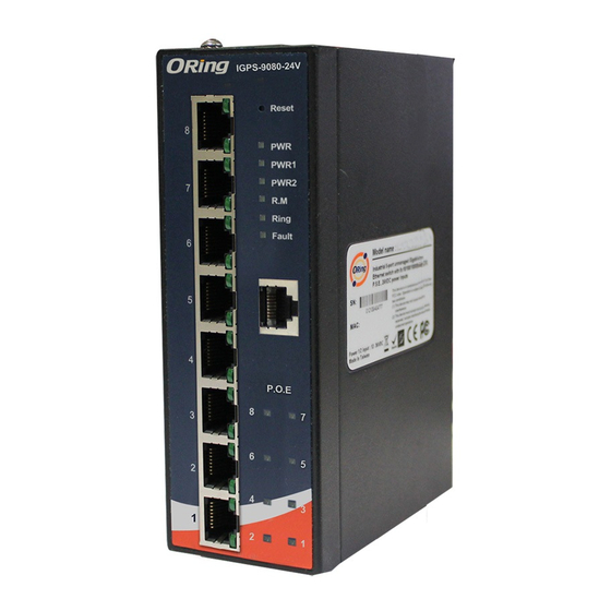
Introduction
The
IGPS-9080 series
is a full-Gigabit managed PoE Ethernet switch with
eight 10/100/1000Base-T(X) P.S.E. ports. The series consists of the IGPS-
9080 and IGPS-9080-24V models to meet different application needs. With
complete support for Ethernet redundancy protocols such as O-Ring
(recovery time < 30ms over 250 units of connection) and MSTP (RSTP/STP
compatible), the series can protect mission-critical applications from
network interruptions or temporary malfunctions with fast recovery
technology. The eight 10/100/1000Base-T(X) P.S.E. ports enable the
device to provide sufficient power for power-hungry devices with up to 30W
per port. With a wide operating temperature from -40 C to 75 C, the device
can be managed centrally via ORing's proprietary Open-Vision platform as
well as via Web-based interfaces, Telnet and console (CLI)
Package Contents
The device is shipped with the following items. If any of these items is
missing or damaged, please contact your customer service representative for
assistance.
Contents
Pictures
Number
IGPS-9080 /
IGPS-9080-24V
CD
DIN-rail Kit
Wall-mount Kit
Console Cable
QIG
Preparation
Before you begin installing the switch, make sure you have all of the package
contents available and a PC with Microsoft Internet Explorer 6.0 or later, for
using web-based system management tools.
Safety & Warnings
Elevated Operating Ambient: If installed in a closed or multi-unit rack
assembly, the operating ambient temperature of the rack environment may be
greater than room ambient. Therefore, consideration should be given to
installing the equipment in an environment compatible with the maximum
ambient temperature (Tma) specified by the manufacturer.
Reduced Air Flow: Installation of the equipment in a rack should be such
that the amount of air flow required for safe operation of the equipment is
not compromised.
Q I G
IGPS-9080
IGPS-9080 Series
G
uide
Dimension
o
o
Reset
PWR
G8
PWR1
PWR2
R.M
G7
Ring
Fault
G6
G5
X 1
G4
802.3at/af PoE
8
7
G3
6
5
4
G2
3
2
1
10/100/
G1
1000T
X 1
IGPS-9080
54.3
X 1
Panel Layouts
Front View
X 1
G8
G7
G6
X 1
G5
G4
G3
X 1
12
G2
11
10/100/
G1
1000T
10
Top Panel
1
1. Terminal blocks: PWR1, PWR2
(12-57V DC for IGPS-9080-24V;
50-57V DC for IGPS-9080), Relay
1907-2-29-IGPS9080-1.1
Mechanical Loading: Mounting of the equipment in the rack should be such that a
hazardous condition is not achieved due to uneven mechanical loading.
Circuit Overloading: Consideration should be given to the connection of the equipment
to the supply circuit and the effect that overloading of the circuits might have on overcurrent
protection and supply wiring. Appropriate consideration of equipment nameplate ratings
should be used when addressing this concern.
32.2
32.0
108.5
32.2
40.0
18.0 18.15
14.0
54.3
Rear View
1
Reset
2
PWR
3
1. Reset button
PWR1
4
PWR2
R.M
5
2. PWR status LED
6
Ring
7
3. PWR1 LED
Fault
4. PWR2 LED
8
5. R.M. status LED
6. Ring status LED
1
1
7. Faulty relay indicator
802.3at/af PoE
8. Console port
8
7
9. PoE indicators for LAN ports
6
5
10. Speed LED for LAN ports
9
4
11. LNK/ACT LED for LAN ports
3
2
12. Gigabit Ethernet ports
1
IGPS-9080
1. Wall-mount screw holes
2. Din-rail screw holes
PRINTED ON RECYCLED PAPER
Industrial Managed PoE Gigabit Switch
Installation
DIN-rail Installation
Step 1: Slant the switch and screw the Din-rail kit onto the back of the switch, right in
the middle of the back panel.
Step 2: Slide the switch onto a DIN-rail from the Din-rail kit and make sure the switch
clicks into the rail firmly.
R2.5
R3.95
Wall-mounting
Step 1: Screw the wall-mount kit onto the rear panel of the switch. A total of six
screws are required, as shown below.
Step 2: Use the switch, with wall mount plates attached, as a guide to mark the
correct locations of the four screws.
51.0
Step 3: Insert a screw head through the large parts of the keyhole-shaped apertures,
and then slide the switch downwards. Tighten the screws for added stability.
2
Network Connection
The switch provides standard Ethernet ports. According to the link type, the switch uses
CAT 3,4,5,5e UTP cables to connect to any other network devices (PCs, servers,
switches,
routers,
or
hubs).
Please
specifications.
Cable Types and Specifications:
Cable
Type
10BASE-T
Cat. 3, 4, 5 100-ohm
100BASE-TX
Cat. 5 100-ohm UTP
1000BASE-T
Cat. 5 / Cat. 5e 100-ohm UTP
Version 1.1
Reset
PWR
G8
PWR1
PWR2
R.M
G7
Ring
Fault
G6
G5
G4
802.3at/af PoE
8
7
G3
6
5
4
G2
3
2
1
10/100/
G1
1000T
IGPS-9080
refer
to
the
following
table
for
cable
Max. Length
Connector
UTP 100 m (328 ft)
RJ-45
UTP 100 m (328 ft)
RJ-45
UTP 100 m (328 ft)
RJ-45
Quick Installation Guide
Advertisement

Related Manuals for ORiNG IGPS-9080-24V


Summary of Contents for ORiNG IGPS-9080-24V
- Page 1 10/100/1000Base-T(X) P.S.E. ports. The series consists of the IGPS- the middle of the back panel. 9080 and IGPS-9080-24V models to meet different application needs. With Circuit Overloading: Consideration should be given to the connection of the equipment Step 2: Slide the switch onto a DIN-rail from the Din-rail kit and make sure the switch...
- Page 2 Dual DC inputs. 50-57VDC on 6-pin terminal block Dual DC inputs. 12-57VDC on 6-pin terminal block manual. For information on operating the switch assignment information. Power consumption(Typ.) using ORing’s Open-Vision management utility, 9 Watts 10 Watts (PoE output not included) please go to ORing website.
Need help?
Do you have a question about the IGPS-9080-24V and is the answer not in the manual?
Questions and answers